1982 VOLVO 940 wheel torque
[x] Cancel search: wheel torquePage 22 of 168
70019401960 Specifications
Section 2 B
19, B 23 Engines
Tightening torques
Apply to oiled nuts and bolts.
Oegreased (washed) parts must be oiled prior to assembly.
Main bearings ....................... ' ....................... .
Connecting rod bearings,
old bolts ............................ .
new
bolts ......... .................. .
Flywheel (use new bolts) ..................................... .
Spark
plugs (unoiled) .............. ; ......................... .
Camshaft sprocket
............... ........................... .
Intermediate shaft sprocket ................................. .. .
Camshaft bearing caps .
............................ ......... .
Crankshaft center
bolt ....................................... .
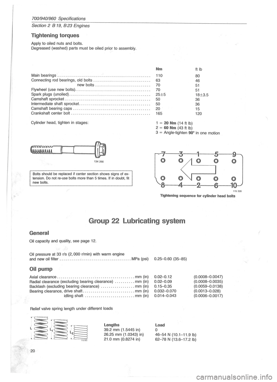
Cylinder head , tighten in stages:
134266
Bolts should be replaced if center section shows signs of extension. Do not re-use bolts more than 5 times . If in doubt, fit
new bolts.
Nm
110
63
70
70
25±5
50
50 20
165
1 = 20 Nm (14 ft Ib)
2 = 60 Nm (43 ft Ib)
ft Ib
80
46
51
51
18±3.5
36
36 15
120
3 = Angle-tighten 900 in one motion
'7--3---
o 0
000
8-4-2-
--9
o
115326
Tightening sequence for cylinder head bolts
Group 22 Lubricating system
General
Oil capacity and quality, see page 12.
Oil pressure at 33 rls (2,000 r/min) with warm engine
and new
oil filter ...... .............................. MPa (psi) 0.25-0.60 (35-85)
Oil pump
Axial clearance .................. ..................... mm (in)
Radial clearance (excluding bearing clearance) .......... mm (in)
Backlash (excluding bearing clearance) ................. mm (in)
Bearing clearance, drive shaft
.......................... mm (in)
idling shaft ..... ........... .......... mm (in)
Relief valve spring length under different loads
~~~ 115083
20
Lengths
39.2 mm (1.5445 in)
26.25 mm (1.0343) in)
21.0 mm (0.8274 in)
0.02-0.12
0.02-0.09
0.15-0.35
0.032-0.070
0.014-0.043
Load
o
(0.0008-0 .0047)
(0.0008-0.0035)
(0.0059-0.0138)
(0.0013-0. 028)
(0.0006-0.0017)
46-54 N (10.1-11.9 Ib)
62 -78 N (13.6-17.2 Ib)
(
Page 43 of 168
(
70019401960 Specifications
Section
2 B 200, B 230 Engines
Bea rings
Main bearings
Two types of main bearings are in use. Upper and lower
shells
on same journal must be same type.
Connect
ing rod bearings
Matched
shells are used in production:
Shells are colour -coded (red, blue, yellow) as follows:
136753
Assembly 1 Two yellow shells.
Assembly
2 One blue and one red.
Blue shell in con-rod and red in cap.
Colour code Note that only yellow-coded shells are kept in stock .
• Late type: also main bearing shells .
Connect ing rods
Axial clearance at piston ............................... mm (in) 0.15-0.45 (0.0059-0.0177)
Max weight deviation between connecting
rods
in same engine ................................. gms (oz.) 20 (0.7)
Flywheel
Axial throw, max ...................................... mm (in) 0.021100 diameter (0.0008/3.9400)
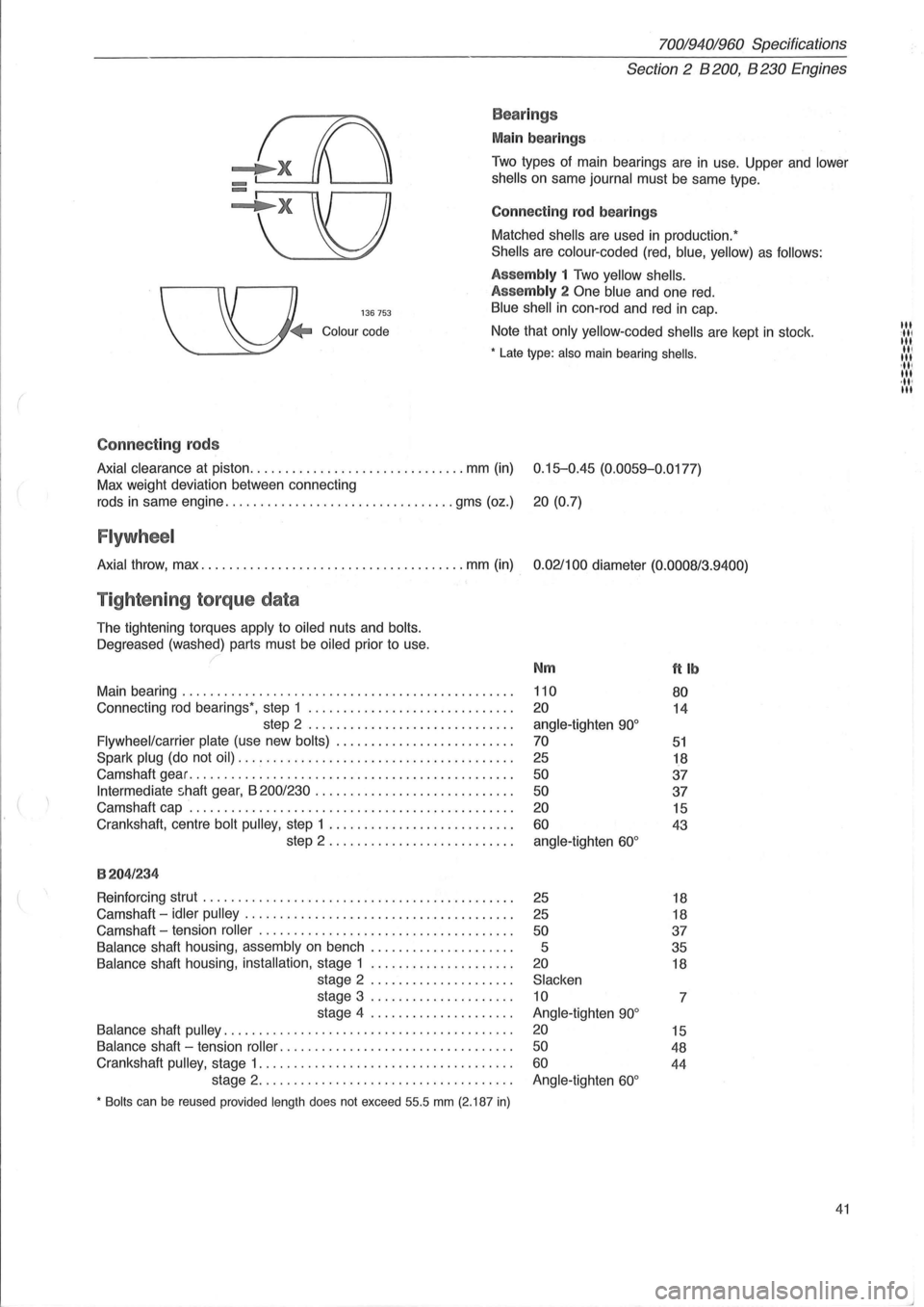
Tightening torque data
The tightening torques apply to oiled nuts and bolts.
Oegreased
(washed) parts must be oiled prior to use.
Main bearing
............................................... .
Connecting
rod bearings', step 1 ............................. .
step 2
............................. .
Flywheel/carrier plate (use new bolts) ...................... ... .
Spark plug (do not oil) ....................................... .
Camshaft gear
.............................................. .
Intermediate shaft gear, B 200/230 ............................ .
Camshaft cap
.............................................. .
Crankshaft, centre
bolt pulley, step 1 .......................... .
step 2 .
.. ....................... .
8204/234
Reinforcing strut ............................................ .
Camshaft -
idler pulley ...................................... .
Camshaft -tension
roller .................................... .
Balance shaft housing, assembly on bench .................... .
Balance shaft housing, installation, stage 1 .................... .
stage 2
.................... .
stage 3
.................... .
stage 4
.................... .
Balance shaft pulley ......................................... .
Balance shaft -tension roller .. ............................... .
Crankshaft
pulley, stage 1 .................................... .
stage 2
.................................... .
• Bolts can be reused provided length does not exceed 55.5 mm (2.187 in)
Nm
110
20
angle-tighten 90°
70
25
50
50
20
60
angle-tighten 60°
25
25
50
5
20
Slacken
10
Angle-tighten
90°
20
50
60
Angle-tighten 60°
ftlb
80
14
51
18
37
37
15
43
18
18
37
35
18
7
15
48
44
41
III :11' III II, III 'III III ,11' III
Page 75 of 168
{
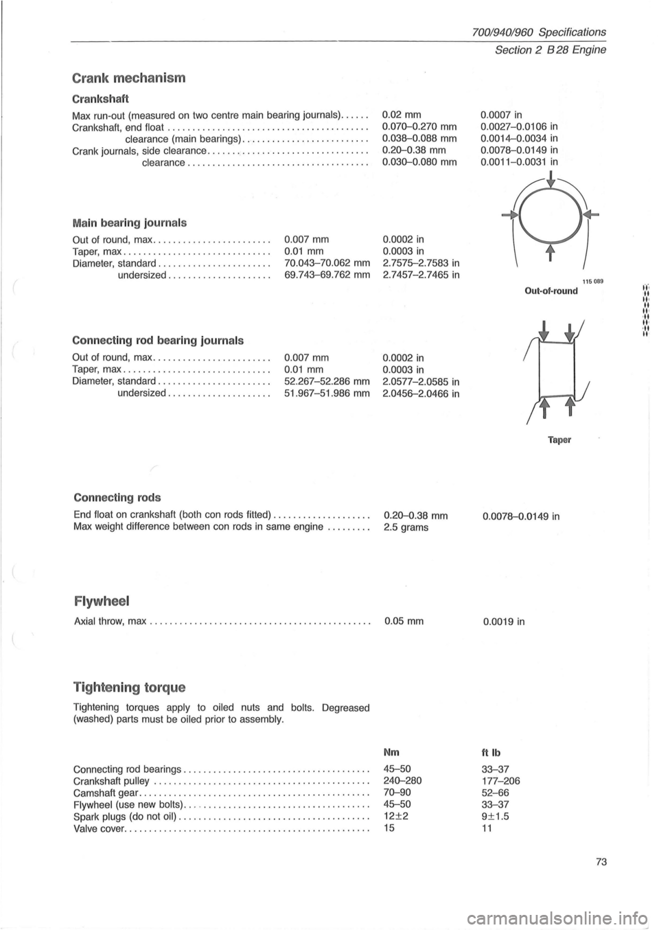
Crank mec ha ni sm
Cr ank sh aft
Max run-out (measured on two centre main bearing journals) ..... .
Crankshaft, end float
........................................ .
clearance (main bearings) ......................... .
Crank
journals, side clearance ...........•.................... .
clearance .................................... .
M ain bea rin g journ als
Out of round, max ....................... .
Taper, max
...... ....................... .
Diameter, standard ...
................... .
undersized
.................... .
Conne cting rod b ea ring journ als
Out of round, max ....................... .
Taper, max
............................. .
Diameter, standard
...................... .
undersized
.................... .
C onnec tin g rods
0 .007 mm
0.01 mm
70.043-70.062 mm
69 .743-69.762 mm
0.007 mm
0.01 mm
52.267-52 .286 mm
51.967-51.986 mm
End
float on crankshaft (both can rods fitted) ................... .
Max weight difference between can rods
in same engine ........ .
Flywh eel
0.02 mm
0 .070-0.270 mm
0.038-0.088 mm
0.20-0.38 mm
0 .030-0.080 mm
0.0002 in
0.0003 in
2.7575-2.7583 in
2 .7457-2.7465 in
0.0002 in
0.0003 in
2.0577-2.0585 in
2.0456-2.0466 in
0.20-0.38 mm
2.5 grams
Axial throw, max . . . . . . . . . . . . . . . . . . . . . . . . . . . . . . . . . . . . . . . . . . . . . 0 .05 mm
T ig hte nin g torq ue
Tightening torques apply to oiled nuts and bolts. Degreased
(washed) parts must be
oiled prior to assembly.
Connecting rod bearings ................. .......... ..... ..... .
Crankshaft
pulley . ........ .......... ........................ .
Camshaft gear
................................. ............. .
Flywheel (use new bolts) ... -................................. .
Spark plugs (do not oil) ...................................... .
Valve cover ......... .................................... .... .
Nm
45-50
240-280
70-90
45-50
12±2
15
70019401960 Specifications
Section 2 B 28 Engine
0 .0007 in
0.0027 -0.0106 in
0.0014-0.0034 in
0.0078-0 .0149 in
0 .0011-0.0031 in
Out-of-round
Taper
0 .0078-0.0149 in
0.0019 in
ttlb
33-37
177 -206
52-66
33-37
9±1.5
11
115089
73
t't'. -II II· II II' ,II II'
,II II'
Page 115 of 168
(
70019401960 Specifications
Section
2 024, 024 T, 024 TIC Engines
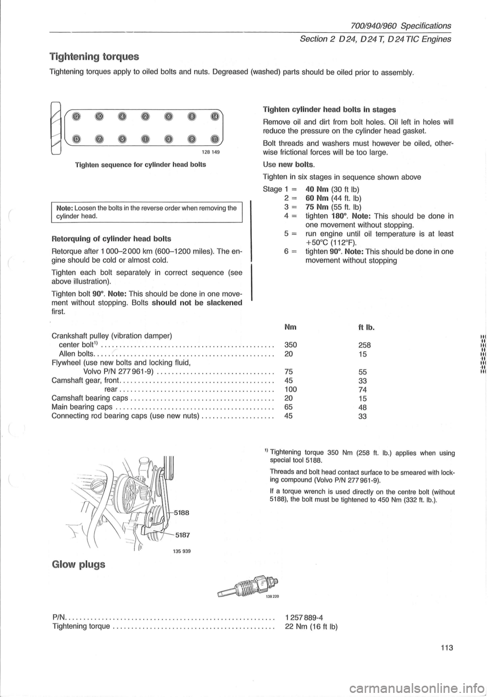
Tig ht enin g to rqu es
Tightening torques apply to oiled bolts and nuts. Oegreased (washed) parts should be oiled prior to assembly .
I' ~ ~ 0 8 CD 0 (IJ
#' ~ G e Q e Q GJ
128149
Tighten
sequence for cylinder head bolts
Note: Loosen the bolts in the reverse order when removing the cylinder head.
R etorquing of cylinder head bolts
Retorque after 1 000-2000 km (600-1200 miles). The en
gine
should be cold or almost cold.
Tighten each bolt separately in correct sequence (see
above
illustration).
Tighten bolt 90°. Note: This should be done in one move
ment without stopping.
Bolts should not be slacken ed
first.
Crankshaft
pulley (vibration damper) Ti
g
hten cylinde r h ea d bolts in stages
Remove oil and dirt from bolt holes. Oil left in holes will
reduce the pressure on the cylinder head gasket.
Bolt threads and washers must however be oiled, other-
wise
frictional forces will be too large.
Use new bolts .
Tighten in six stages in sequence shown above
Stage 1 = 40 Nm (30 ft Ib)
2 = 60 Nm (44 ft. Ib)
3 = 75 Nm (55 ft. Ib)
4 = tighten 180°. Note: This should be done in
one movement without stopping .
5
= run engine until oil temperature is at least
+50°C (112°F).
6 = tighten 90°. Note: This should be done in one
movement without stopping
Nm
ft lb.
center bolt1) ............................... ............... . 350 258
Allen bolts ..... :: ......................................... . 20 15
Flywheel (use new bolts and locking fluid,
Volvo PIN
277 961-9) ............................... .
75
55
Camshaft gear, front
......................................... .
45
33
rear
....................................... .. . 100 74
Camshaft bearing caps .................................... .. . 20 15
Main bearing caps .......................................... .
65 48
Connecting rod bearing caps (use new nuts)
................... .
45
33
1) Tightening torque 350 Nm (258 ft. lb.) applies when using special tool 5188.
5187
G lo w plugs
Threads and bolt head contact surface to be smeared with locking compound (Volvo PIN 277961-9).
If a torque wrench is used directly on the centre bolt (without 5188), the bolt must be tightened to 450 Nm (332 ft. lb.) .
PIN.
. . . . . . . . . . . . . . . . . . . . . . . . . . . . . . . . . . . . . . . . . . . . . . . . . . . . . . . . 1 257889-4
Tightening
torque. . . . . . . . . . . . . . . . . . . . . . . . . . . . . . . . . . . . . . . . . . . . 22 Nm (16 ft Ib)
113
'il IN 11 '11 11
·11 III
Page 142 of 168
70019401960 Specifications
Section 4 Power Transmission
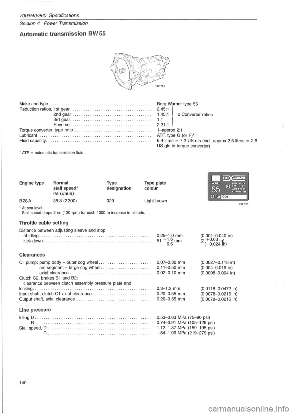
Automat ic transmission BW 55
Make and type .. ............................................ .
Reduction ratios, 1 st gear ..
................. ................. .
2nd gear
................................... .
3rd gear
................... ................. .
Reverse
.................................... .
Torque converter, type ratio
................................ .. .
Lubricant.
........................... ....................... .
Fluid capacity .................... ........................... .
* ATF = automatic transmission fluid.
1.45:1 x Converter ratios
Borg
Wirner type
55
2.45 :1
1 : 1
2.21 : 1
1-approx 2:1
ATF, type G (or F)*
6.9
litres = 7.2 US qts (inc!. approx 2.5 litres = 2 .6
US qts in torque converter)
.~ Engine type Normal
stall speed*
rls (r/min)
Type
designation
Type plate
colour
....... WAOIIHUH
55 e:> ~~D ~~~I~ f'"OUTUTAUS
B28A 38.3 (2300) 029 SERIAl~ Light brown 131755 * At sea level.
Stall speed drops 2 rls (120 rpm) for each 1000 m increase in altitude .
Throttle cable setting
Distance between adjusting sleeve and stop
at idling .................................................. .
kick -down
........................ ........................ .
C leara nces
Oil pump: pump body -outer cog wheel ....................... .
arc segment -
large cog wheel ...................... .
axial clearance .................................... .
Clutch C2, brakes B1 and B2:
clearance between
clutch assembly pressure plate and
locking ..................................................... .
Input shaft, clutch C1 axial clearance .......................... .
Output shaft,
axial clearance ................................. .
Line pressure
Idling D .................................................... .
R ..................... .... ........................... .
Stall speed, D .................. .............. ...... ........ .
R .............................................. .
140 0.25-1
.0
mm 51 +1.6mm -0.6
0.07-0.30 mm
0.11-0 .50 mm
0.02-0.10 mm
0.3-1 .2 mm
0.20-0 .55 mm
0.20-0.55 mm
(0.001-0.040 in) (2 +0.63 in) (-0.024Ih)
(0.0027-0.118 in)
(0.004-0 .019 in)
(0.0008-0.004 in)
(0.0118-0 .0472 in)
(0.0078-0.0216 in)
(0.0078-0.0216 in)
0.53-0.63 MPa (75-90 psi)
0.74-0.91 MPa (105-129 psi)
1 .12 -1.37
MPa (159-195 psi)
1.54-1.96
MPa (219-279 psi)
Page 153 of 168
(
70019401960 Specifications
Section
4 Power Transmission
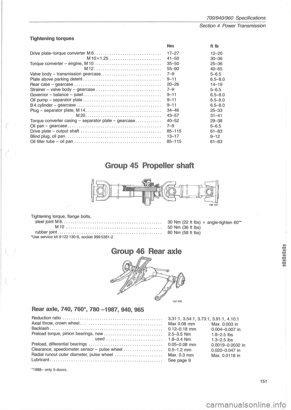
Tig ht enin g to rqu es
Nm ftlb
Drive plate-torque converter M 8 ................ .............. . 17-27 12-20
M10x 1.25 ......... .............. . 41-50 30-36
Torque converter -engine, M 10 .............................. . 35--50 25--36
M12 ........................ ...... . 55--90 40-65
Valve body -transmission gearcase ....................... .... . 7-9 5--6.5
Plate above parking detent ............ ............ ........... . 9--11 6.5--8 .0
Rear case -gearcase .............................. ......... . 20-26 14-19
Strainer - valve body -gearcase ................ ............ . . 7- 9
5--6.5
Governor -balance -pawl .......... ......................... . 9--11 6.5--8.0
Oil pump -separator plate .................. ................ . . 9--11 6.5--8 .0
B 4 cylinder -gearcase ...................................... . 9--11 6.5--8 .0
Plug -separator plate, M 14 .................................. . 34-46 25--33
M20 ....... ................ ...... ..... . 43- 57
31-41
Torque converter casing -separator plate -gearcase ........... . 40-52 29-38
Oil pan -gearcase .......................................... . 7-9 5--6.5
Drive plate -output shaft .................................... . 85--115 61-83
Blind plug, oil pan .................... ................. ...... . 13-17 9--12
Oil filler tube -oil pan ....................................... . 85--115 61-83
Group 45 Propeller shaft
/'
Tightening torque, flange bolts,
steel
joint M 8 ....................... ...... ..............•..
M10 ......................... .. ................ .
rubber joint ...................................... ......... . *Use service kit 9122130-9, socket 9995381 -2
ikd@
1 39 137
30 Nm (22 ft Ibs) + angle-tighten 60°*
50 Nm (36 ft Ibs)
80 Nm (58 ft Ibs)
Group 46 Rear axle
Rear axle , 740 , 760* , 780 -1987, 940 , 965
Reduction ratio ...................................... ....... . 3 .31:1, 3.54:1 , 3.73:1, 3 .91:1, 4 .10 :1 Axial throw, crown wheel ..................................... . Max 0.08 mm Max . 0.003 in Backlash ... ................................................ . 0 .12-0.18 mm 0 .004-0.007 in Preload torque, pinion bearings, new .......................... . 2.5--3.5 Nm 1.8-2.5 Ibs used ...... ... ................ . 1.8-3.4 Nm 1.3-2.5 Ibs
Preload, differential bearings ................................. . 0 .05--0 .08 mm 0.0019-0 .0032 in Clearance , speedometer sensor -pulse wheel .... .. ........... . 0 .5--1.2 mm 0 .020-0.047 in Radial runout outer diameter, pulse wheel ........ : .. : ......... . Max . 0.3 mm Max . 0.0118 in Lubricant ....... . ........................................... .
See page 9
*1988--only 5- doors.
151
III 1 .... 1 III ·111 III ·111 III ·111
Page 154 of 168
70019401960 Specifications
Section
4 Power Transmission
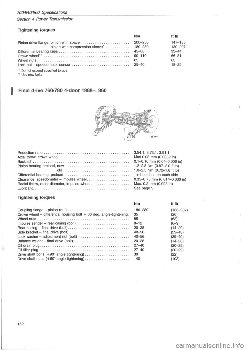
Tightening torqu es
Pinion drive flange, pinion with spacer .......... ........ ....... .
pinion with compression
sleeve ' ............ .
Differential bearing caps .............................. ...... . .
Crown
wheel " .. ............................ .......... ...... .
Wheel nuts ...... ............................... .. .......... .
Lock nut -speedometer sensor .
............................. .
• Do not exceed specified torque .. Use new bolts.
I Final drive 760 /780 4-door 1988-, 960
Reduction ratio ................................... .......... .
Axial throw , crown wheel ..................................... .
Backlash ............... .................................... .
Pinion bearing
preload , new .................................. .
old ........ .. ..... .................... .
Differential bearing, preload .................................. .
Clearance , speedometer' -impulse wheel ....... ............... .
Radial throw , outer diameter, impulse wheel ....... ............. .
Lubricant.
..... ............................................. .
T ightening torque s
='.. Coupling flange -pinion (nut) ................................ .
Crown
wheel -differential housing bolt + 60 deg . angle-tightening.
Wheel nuts .. ............................. .................. .
Impulse sender -rear casing (bolt) ............................ .
Rear casing -
final drive (bolt) ................................ .
Side bracket -final drive (bolt) ............................... .
Lock washer -adjustment nut
(bolt) ........................... .
Balance weight -final drive (bolt) ............................. .
Oil drain plug ............................................... .
Oil filler plug ................................................ .
Drive shaft
bolts (+900 angle tightening) ....................... .
Drive shaft nuts,
(+600 angle tightening) ............... ........ .
152
Nm ttlb
200-250 147-185
180-280 130-207
45-60 33-44
90-110 66-81
85 63
25-40 18-29
3.54:1, 3.73:1, 3.91:1
Max 0.08 mm (0.0032 in)
0.1-0. 16 mm (0.04--0 .006 in)
1.2-2.8 Nm (0.87 -2.0 ft Ib)
1.0-2.5 Nm (0.72-1 .8 ft Ib)
1 + 1 notches on each side
0.35-0.75 mm (0.014--0.030 in)
Max.
0.2 mm (0. 008 in)
See page 9
Nm
180-280
35
85
8-12
20-28
40-56
40-56
20-28
27-40
27-40
30
140
ftlb
(133-207)
(26)
(63)
(6-9)
(14--20)
(29-40)
(29-40)
(14--20)
(20-29)
(20-29)
(22)
(103)
Page 155 of 168
70019401960 Specifications
Section
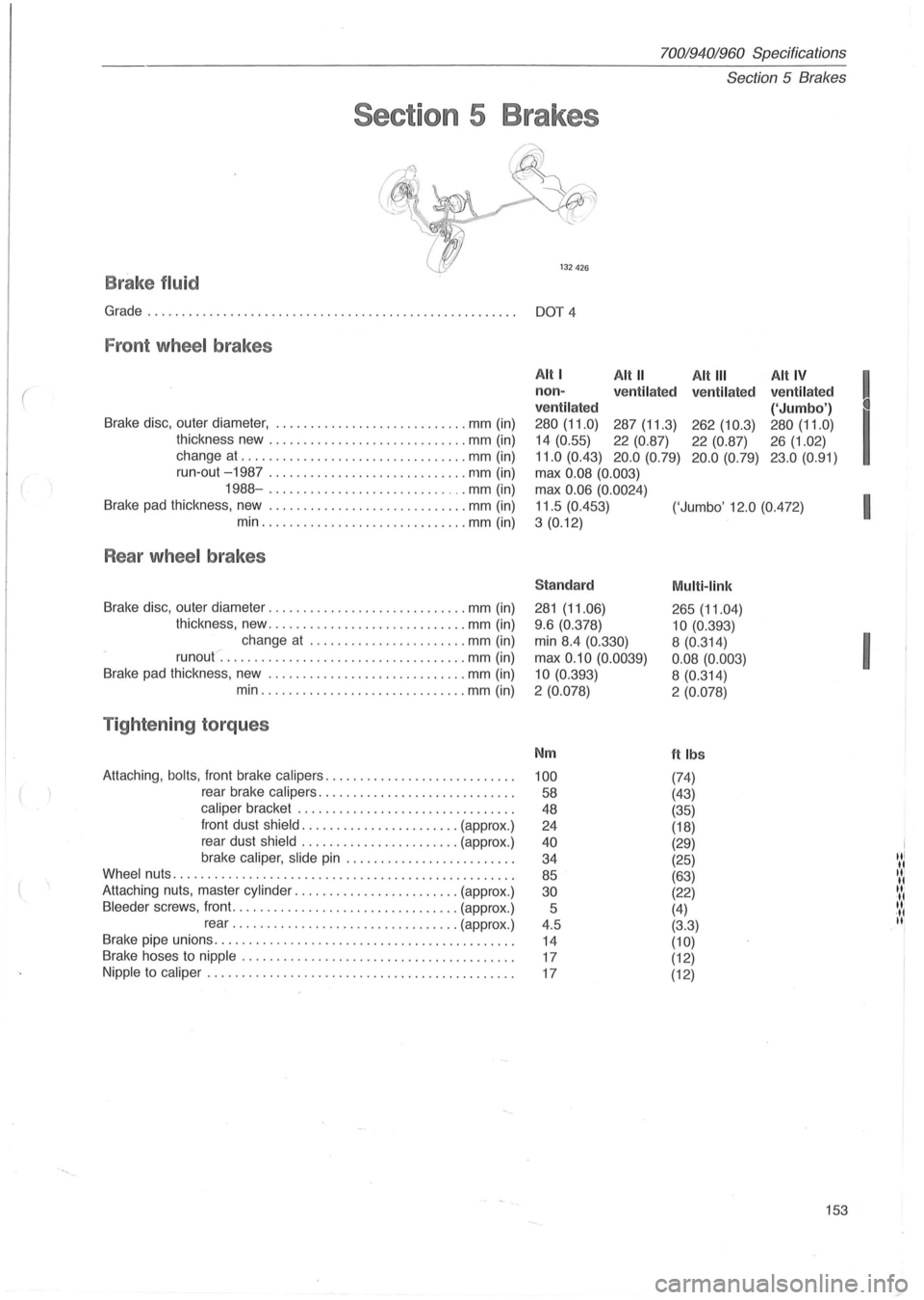
5 Brakes
Section 5 Brakes
fJy ~~
132426
B rake fluid
Grade................................... .... ... ............ DOT 4
Fron t wheel brakes
(
Brake disc, outer diameter, .. .................... .. .... mm (in)
thickness new
............................ . mm (in)
change at
........ ........... .............. mm (in)
Alt I Alt" Alt III Alt IV
! non -
ve ntil ated
ve ntilat ed ventilated
ventil ated
('Jumbo')
I
280 (11.0) 287 (11.3) 262 (10.3) 280 (11.0)
14 (0.55)
22 (0.87)
22 (0.87) 26 (1.02)
11.0 (0.43) 20.0 (0.79) 20 .0 (0. 79) 23.0 (0.91)
run-out -1987 ... ....... .. ................. mm (in)
max 0.08 (0.003)
1988-.................. ........... mm (in)
Brake pad thickness, new .
............................ mm (in)
min
.... ............ ........... ... mm (in) max
0
.06 (0.0024)
I 11.5 (0.453)
('Jumbo' 12.0 (0.472)
3
(0. 12)
Rear wheel brakes
Sta ndard Multi -link
Brake disc, outer diameter ....... ...................... mm (in) 281 (11.06)
265 (11.04)
thickness, new ............................. mm (in)
change at
............... ........ mm (in)
runout .
...................... ............. mm (in)
Brake pad thickness , new .
..... ....... ............... . mm (in) 9
.6 (0.378)
10 (0.393)
I
min 8.4 (0.330) 8 (0.314)
max
0.10 (0.0039)
0.08 (0.003)
10
(0. 393)
8 (0.314)
min ............ .................. mm (in)
2 (0.078) 2 (0.078)
T ight enin g torque s
Nm ftlbs
Attaching , bolts , front brake calipers ........................... . 100 (74)
rear brake calipers ............................ .
58 (43)
caliper bracket ....................... ....... . .
48 (35)
front dust
shield .................... ... (approx .)
24 (18)
rear dust
shield ................ ....... (approx.)
brake
caliper, slide pin ................... ..... .
40 (29)
"I 34
(25) II Wheel nuts ................................................. .
85 (63) II II Attaching nuts, master cylinder ..... ................... (approx.) 30 (22) II II Bleeder screws, front ......................... ........ (approx .)
5 (4) II ·11 rear ...... .......... ................. (approx .)
4.5 (3.3) II
Brake pipe unions ...... .......... ............ ............... .
14 (10) Brake hoses to nipple ....................................... .
17 (12)
Nipple to caliper ......... ................................... .
17 (12)
153