1982 VOLVO 940 diagram
[x] Cancel search: diagramPage 24 of 168
700/919!~o,(}).spe(jifiJjations
Section 2 819, 823 Engines
CI system (B 19 E, B 19 El, B 23 E)
Pressures B19ET
Line pressure ....................................... kPa (psi)
B19E, B23 E
450-530 (64-75)
150-240 (21-34)
520-580 (74-82)
240-320 (34-46) Rest pressure ................................ ....... kPa (psi)
Control pressure
warm engine ...................................... kPa (psi)
345-375 (49-53)
345-375 (49-53)
295-325 (42-46)
warm engine and charge pressure of
45 kPa (6.4 psi) ................................... kPa (psi)
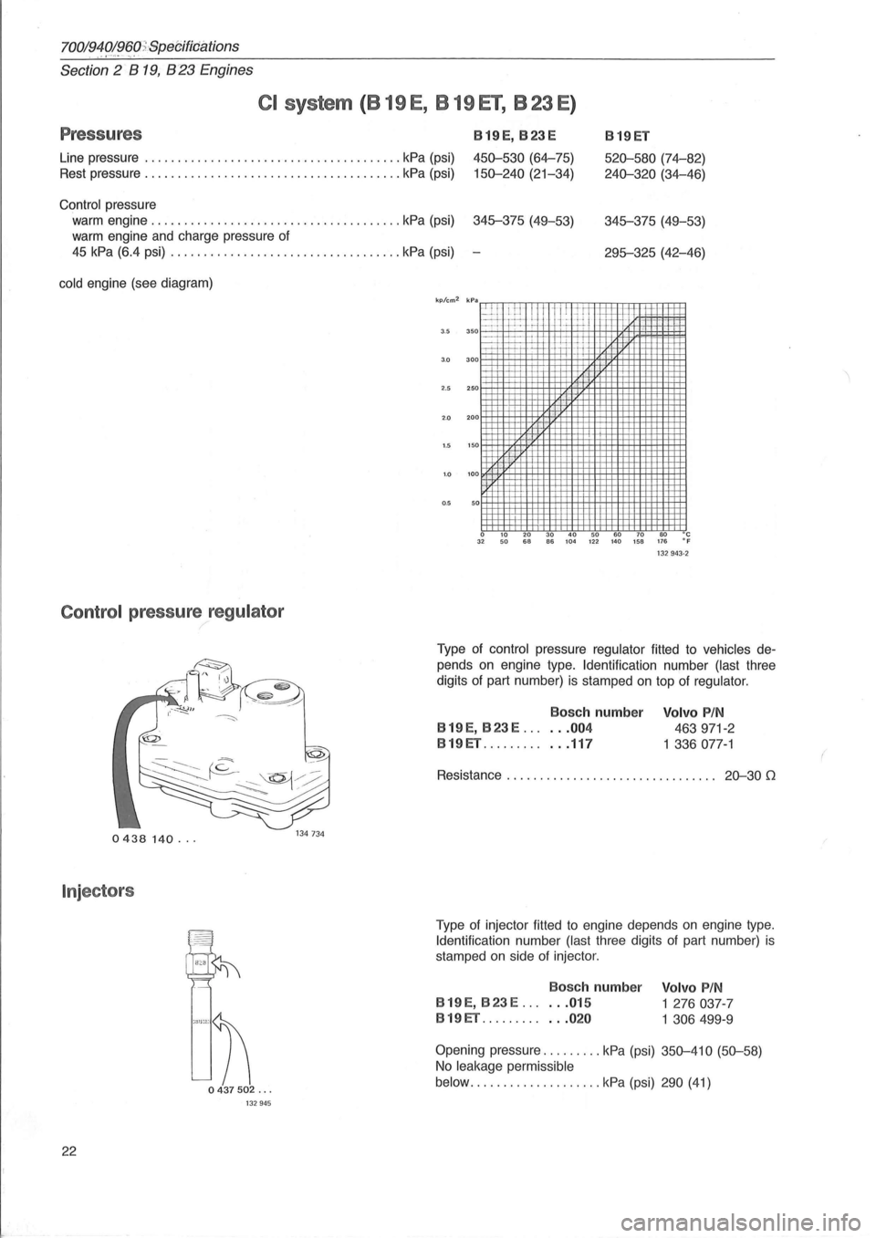
cold engine (see diagram)
Control pressure regulator
0438140 ...
Injector s
22
"" ' n
0437502 ... 132945
2.5 250
2.0 200
1 .5 150
1.0 100
0.5 50
o 10 20 30 40 50 60 70 80 D C 32 50 68 66 104 122 140 158 176 e F 132943·2
Type of control pressure regulator fitted to vehicles de
pends
on engine type. Identification number (last three
digits
of part number) is stamped on top of regulator .
Bosch number
B 19 E,
B23E ...... 004
B19ET ............ 117
Volvo PIN
463971-2
1 336
077-1
Resistance . . . . . . . . . . . . . . . . . . . . . . . . . . . . . . .. 20-30 (1
Type of injector fitted to engine depends on engine type.
Identification number (last three digits of part number) is
stamped on side of injector .
Bosc h number
B 19 E,
B23E ...... 015
B 19 ET ............ 020 Volvo
PIN
1
276037-7
1 306499-9
Opening pressure
......... kPa (psi) 350-410 (50-58)
No leakage permissible
below
.............. ...... kPa (psi) 290 (41)
Page 50 of 168
70019401960 Specifications
Section
2 B 200, B 230 Engines
B 200 E , B 230 E: CI System
. Pressures
Line pressure .............. kPa (psi) 450-530
(64-75)
Rest pressure .............. kPa (psi) 150-240
(21-34)
Control pressure
warm engine ............. kPa (psi) 345-375
(49-53)
cold engine, see diagram
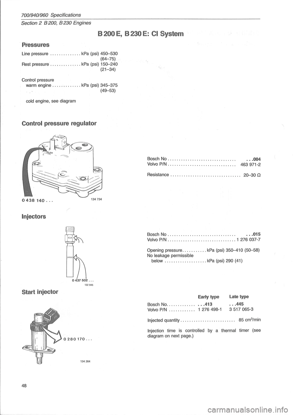
Control pressure regulator
0438 140 ...
Injectors
""n
0437502 ... 132945
Start injector
0280170 ...
134264
48
'.
Bosch No ............. ...... " . . .. . .. .. . . .. 004
Volvo PIN ............................. " 463 971-2
Resistance . . . . . . . . . . . . . . . . . . . . . . . . . . . . . .
.. 20-30 (2
Bosch No . . . . . . . . . . . . . . . . . . . . . . . . . . . . . . . . .. 015
Volvo PIN ............................... 1 276037-7
Opening pressure ........... kPa (psi) 350-410 (50-58)
No leakage permissible
below ................... kPa (psi) 290 (41)
Early type Late type
Bosch No ................ 413 ... 445
Volvo PIN.. .. .. . .. ... 1 276 498-1 3 517 065-3
Injected
quantity. . . . . . . . . . . . . . . . . . . . . . . .. 85 cm3/min
Injection time is controlled by a thermal timer (see
diagram
on next page.)
Page 79 of 168
70019401960 Specifications
Section 2 B 28 Engine
CI-SYSTE M (8 28 E , 8 28 F)
Pressures
Line pressure .............. ......................... ........ . 470-550 kPa (67-78 psi)
240-320 kPa (34-45 psi)
Rest pressure ....... .............. ..... .................... .
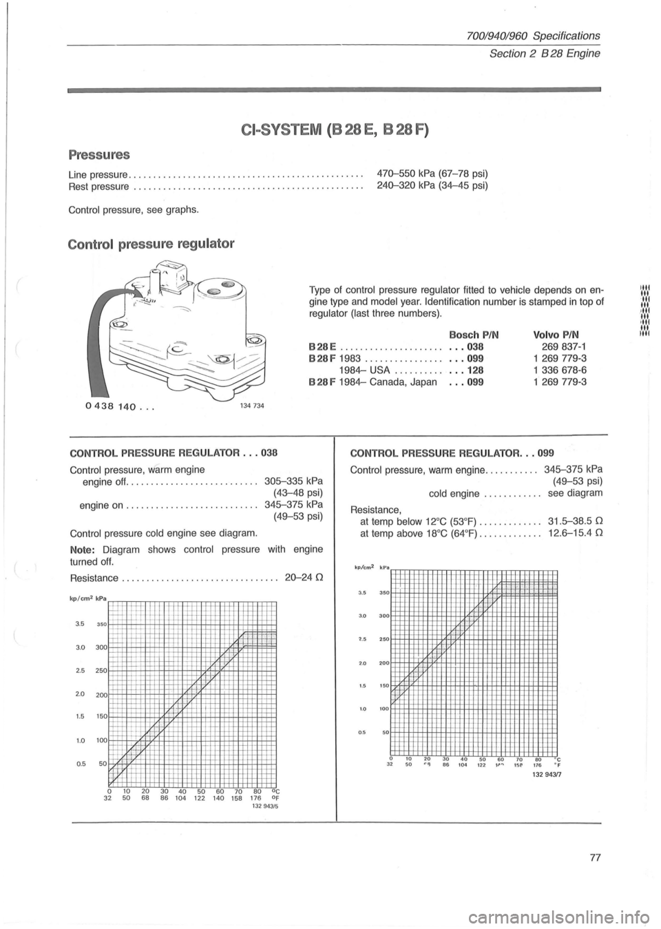
Control pressure , see graphs .
Contr ol press ure reg ulato r
Type of control pressure regulator fitted to vehicle depends on en
gine type and
model year. Identification number is stamped in top of
regulator (last three numbers).
Volvo PIN
B28E .................... .
Bosch PIN
... 038
... 099
. . . 128
... 099
269 837-1
1 269779-3
1 336678-6
1
269779-3
B28F 1983 ... ..... ....... .
1984-USA ....... .. .
B 28 F 1984-Canada, Japan
0438 140 ... 134734
CONTROL PRESSURE REGULATOR ... 038
Control
pressure, Warm engine
engine off. . . . . . . . . . . . . . . . . . . . . . . . . ..
305-335 kPa
(43-48 psi)
engine
on . . . . . . . . . . . . . . . . . . . . . . . . . .. 345-375 kPa
(49-53 psi)
Control pressure cold engine see diagram.
Note: Diagram shows control pressure with engine
turned
off.
Resistance . . . . . . . . . . . . . . . . . . . . . . . . . . . . . . .. 20-24 0
3.5
3 .0
2.5 250
2 .0 200
1.5 150
1 .0 100
0 .5 50
o 10 2 0 30 40 50 60 70 80 oc 3 2 50 68 86 104 122 140 158 176 of 132 943 /5
CONTROL PRESSURE REGULATOR ... 099
Contro l
pressure, warm engine ........... 345-375 kPa
(49-53 psi)
cold engine . . . . . . . . . . .. see diagram
Resistance,
at temp below 12°C (53 °F) . . . . . . . . . . . .. 31.5-38.5 0
at temp above 18°C (64°F) . . . . . . . . . . . .. 12.6-15.4 0
kp/cm2
kPa FFFffi+flFfFm+R=R=FfFmm+!=FfFl+R
3.5 350
3 .0
300
'2.5 250
2.0 200
1.5 1 5 0
1.0 100
0 .5 50
a 10 20 30 40 50 60 70 BO °C 3 2 50
lilt III lit III .Iltl III
'II' III lilt
Page 106 of 168
70019401960 Specifications
Section
2 B 6304 Engine
I
150425
o 580 464 ...
145791
145792
Sil
104
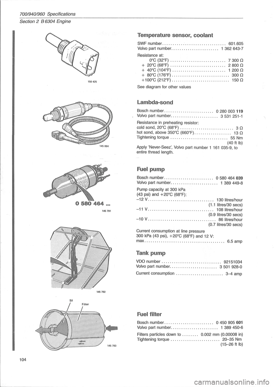
Temperature sensor, coolant
SWF number. . . . . . . . . . . . . . . . . . . . . . . . . . . . . .. 601.605
Volvo part number ....................... 1 362643-7
Resistance
at:
O°C (32°F) . . . . . . . . . . . . . . . . . . . . . . . . . .. 7 300 0
+ 20°C (68°F) . . . . . . . . . . . . . . . . . . . . . . . . . .. 2 800 0
+ 40°C (104°F) . . . .. . . .. . .. . .. . . . . . . . . . .. 1 200 0
+ 80°C (176°F) . . . . . . . . . . . . . . . . . . . .. . . . . . .. 300 0
+100°C (212°F)
............................ 1500
See diagram for other values
Lambda-sond
Bosch number. . . . . . . . . . . . . . . . . . . . . . .. 0 280 003 119
Volvo part number ....................... 3531 251-1
Resistance
in preheating resistor:
cold sand, 20°C (68°F) . . . . . . . . . . . . . . . . . . . . . . . . .. 3 0
hot sand, above 350°C (660°F). . . . . . . . . . . . . . . . .. 13 0
Tightening torque . . . . . . . . . . . . . . . . . . . . . . . . . . .. 55 Nm
(40 ft Ib) Apply 'Never-Seez', Volvo part number 1 161 035-9, to
entire thread
length.
Fuel pump
Bosch number. . . . . . . . . . . . . . . . . . . . . . .. 0 580 464 039
Volvo part number. . . . . . . . . . . . . . . . . . . . . .. 1 389449-8
Pump capacity at 300 kPa
(43 psi) and +20°C (68°F):
-12 V . . . . . . . . . . . . . . . . . . . . . . . . . . . . . . .. 130 lit res/hour
(1.1 litres/30 secs)
-11 V. . . . . . . . . . . . . . . . . . . . . . . . . . . . . . .. 108 litres/hour
(0.9 Iitres/30
secs)
-10 V. . . . . . . . . . . . . . . . . . . . . . . . . . . . . . . .. 86 litres/hour
(0.7 litres/30
secs)
Current consumption
at line pressure
300 kPa (43 psi), +20°C (68°F) and 12 V:
max ................................ ....... 6.5 amp
Tank pump
VDO number. . . . . . . . . . . . . . . . . . . . . . . . . . . .. 92151034
Volvo
part number ....................... 3501 928-0
Current consumption . . . . . . . . . . . . . . . . . . . . . .. 3-4 amp
Fuel filter
Bosch number. . . . . . . . . . . . . . . . . . . . . . .. a 450 905 601
Volvo part number. . . . . . . . . . . . . . . . . . . . . .. 1 389 450-6
Filters particles
down to . . . . . . .. 0.002 mm (0.00008 in)
Tightening torque . . . . . . . . . . . . . . . . . . . . . .
.. 20-35 Nm
(15-26 ft Ib)
Page 157 of 168
(
70019401960 Specifications
Section
6 Suspension and steering
Section 6 Front end and steering
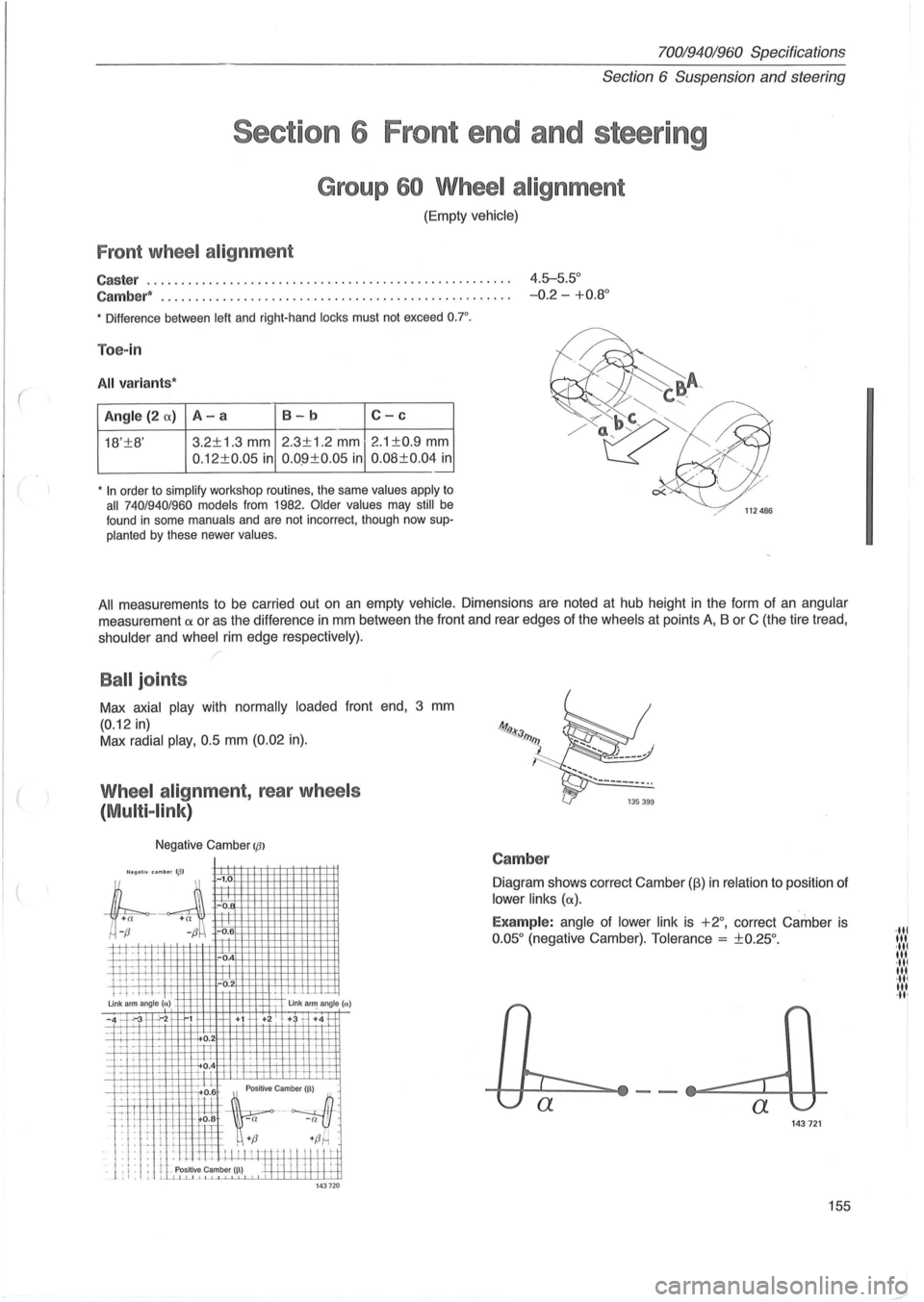
Group 60 Wheel alignment
(Empty vehicle)
Front wheel alignment
Caster ..................................................... 4.5-5.5°
Cambe r*
... ................................... ........ ..... -0.2 -+0.8 °
• Difference between left and right-hand locks must not exceed o.r.
Toe-in
All variant s*
Angle (2 (X) A-a 8-b C-c
18'±8' 3.2±1
.3 mm 2.3±1.2 mm 2 .1 ±0.9 mm
0 .12±0.05 in 0.0 .9±0.05 in 0.08±0.04 in .-
• In order to simplify workshop routines, the same values apply to all 740/940/960 models from 1982. Older values may still be
found in some manuals and are not incorrect, though now supplanted by these newer values.
All measurements to be carried out on an empty vehicle. Dimensions are noted at hub height in the form of an angular
measurement a or as the difference in mm between the front and rear edges of the wheels at points A, B or C (the tire tread,
shoulder and wheel rim edge respective ly).
Ball joints
Max axial play with normally loaded front end, 3 mm
(0.12 in)
Max radial play, 0.5 mm (0.02 in).
Wheel alignment, rear wheels
(
Multi -link )
Negative Camber IfJl
'legall. umb .. 113' -1.0
;l
+
a +a ~ -0.
r;-~ -0.6
P--I I
ii I-i . IT -'. ! . -.1-Un k arm angle (n)
-0
-0
.
Un k a~ angle (a)
-4 -'.-3 "';-2 1 +i +2 + +4 1-
-~~ u ~ 1"'--H---. 1-i-J:-L
_. f-L -\-;-_1_ i-'-1.L?.4 h-
"Lllft~~~~
L.l. f:l+ ~:; +fJ~ .
: I : . : . ill I I I I I m t I " " "! i _ J . ,. . I Positive Camber I~) H 1-1 I I II II ~ t ,I. L LLLu....L1 143 720
Camber
Diagram shows correct Camber (fj) in relation to position of
lower links (a).
Examp le: angle of lower link is +2°, correct Camber is
0 .05 ° (negative Camber). Tolerance = ±0.25°.
143721
155
·ltl III ·ltl It •. ·ltl III ·ltl 'It ·It '