1982 VOLVO 700 water pump
[x] Cancel search: water pumpPage 9 of 168

(
Carburettor
Fuel pump
Clutch
Alternator ,
Steering box
SU
Pierburg
Solex Pierburg
Bosch
AC- oelco
Sofabex
Fichtel & Sachs
Verto/Valeo
Bosch
Cam Gear
Zahnrad Fabrik (ZF)
~
'?' .'" ... .
.
---
" .. u.·.. ,
2
3
5
2
3
4
5
2
3
1
2
3
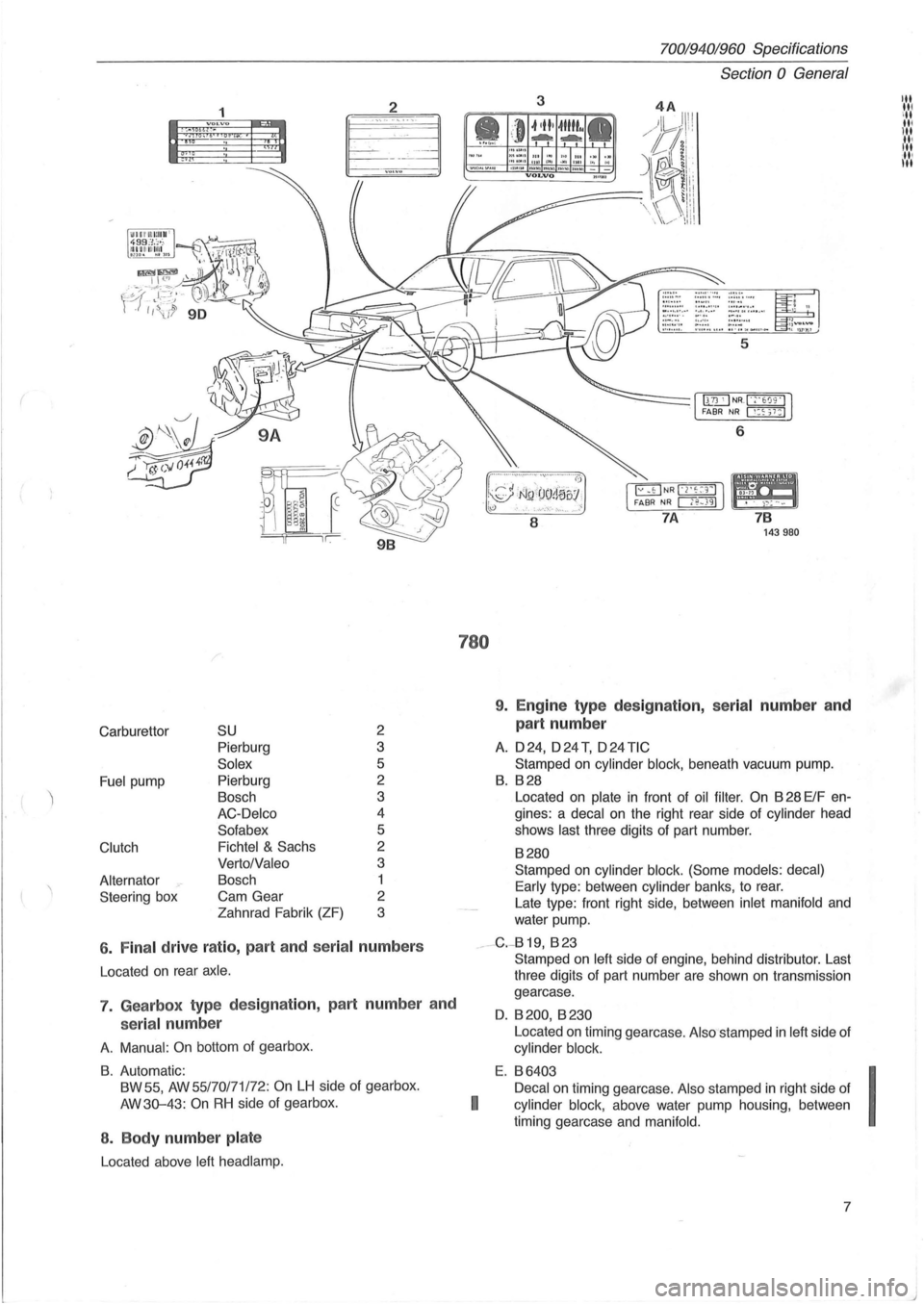
6 . Fina l drive ratio , part and seria l numbers
Located on rear axle .
7. Gearbox type des ig nation, part numbe r and
serial num ber
A. Manual : On bottom of gearbox .
B. Automatic:
BW 55,
AW 55/70171 /72: On LH side of gearbox.
AW3Q-43:
On RH side of gearbox.
8 . Body number pla te
Located above left head lamp.
780
70019401960 Specifications
Section
0 General
3
6
8
7 B 143980
9. Engine type des ig nation, serial number an d
part number
A. 024, o24T, o24TIC
Stamped on cylinder block, beneath vacuum pump.
B. B28
Located on plate in front of oil filter . On B 28 ElF en
gines: a
decal on the right rear side of cylinder head
shows
last three digits of part number.
B280
Stamped on cylinder block. (Some models: decal)
Early
type : between cylinder banks, to rear.
Late type: front right side, between
inlet manifold and
water pump.
__ -G.-819, B 23
I
Stamped on left side of engine, behind distributor. Last
three digits of part number are shown
on transmission
gearcase.
O. B 200, B 230
Located on timing gearcase . Also stamped in left side of
cylinder block.
E. B6403
Decal
on timing gearcase. Also stamped in right side of
cylinder block, above water pump housing , between
timing gearcase and
manifold.
7
I
J
Page 103 of 168

(
Connecting rod bearing caps (stage 1) ................ Nm (ft Ib)
(stage 2) angle-tightening ......... 0
Crankshaft pulley (vibration damper), center bolt ........ Nm (ft Ib)
Flange bolts, vibration damper (stage 1) ............... Nm (ft Ib)
(stage 2) angle-tightening ........ 0
Driver plate (stage 1) ......................... ....... Nm (ft Ib)
(stage 2) angle-tightening ......................... 0
Camshaft wheel. .................................... Nm (ft Ib)
Tensi oning pulley, camshaft timing belt ................ Nm (ft Ib)
Damper unit, camshaft timing belt ..................... Nm (ft Ib)
Angle pulley, camshaft timing belt ..................... Nm (ft Ib)
Water pump ........................................ Nm (ft Ib)
Pin bolts, exhaust manifold (in cylinder head) ........... Nm (ft Ib)
(to front pipe) .............. Nm (ft Ib)
Oil sump pan ....................................... Nm (ft Ib)
Plug, oil sump ...................................... Nm (ft Ib)
Oil suction line ...................................... Nm (ft Ib)
Oil cooler, connector block ........................... Nm (ft Ib)
Oil trap ............................................ Nm (ft Ib)
Nipple, oil·filter ...................................... Nm (ft Ib)
Oil pressure switch .................................. Nrn (ft Ib)
Impulse sensor ..................................... ~~m (ft Ib)
Knock sensor ....................................... Nm (ft Ib)
Temperature sensor, rear edge of top cover ............ Nm (ft Ib)
Temperature sensor, thermostat ............... ....... Nm (ft Ib)
Plug, O-adjustment tool .............................. Nm (ft Ib)
Spark plugs ... ..................................... Nm (ft Ib)
20
90
300±30
35
60 45
50
20±2
39±5
24±4
24±6
17±3
20±3
35±5
17±3
38±5
17±3
17±3
15±2.5
40±2
40±5
8±2
20±2
20±2
10±2.5
38±6
25
Group 22 Lubricating System
Genera l
Oil fill volume and type, see p. 12.
Oil pressure with warm engine and new oil filter :
at 12,5 rls (750 rim), at least ....... ................ Mpa (psi) 0.1
at
50 rls (3 000 rim), at least ....................... Mpa (psi) 0.3
max
...................... ....................... Mpa (psi) 0.5
Lubricat ing oil pump
Relief valve spring, length under various loads
unloaded
.................... ....... mm (in)
loaded to 52±4 N (5.2 kp) ....... .... mm (in)
loaded to 85±8 N (8.5 kp) ........... mm (in)
82.13
56.1
39.9
70019401960 Specifications
Section 2 B 6304 Engine
(15)
(221 ±22)
(26)
(33)
(15±1.5)
(29±4)
(18±3)
(18±4)
(13±2)
(15±2)
(26±4)
(13±2)
(28±4)
(13±2)
(13±2)
(11 ±2)
(29±1.5)
(29±4)
(6±1.5)
(15±1.5)
(15±1.5)
(7±2)
(28±4)
(18)
(14)
(43)
(71 )
(3.233) (2.21)
(1.57)
101
I ..... ' '.','
"' ,III III ill u,1
Page 119 of 168

(
General
024
Capacity: with manual
gearbox ......... litres (US qts) 9.5
(9.9)
with
aut.
gearbox ......... litres (US qts) 9.2
(9.7)
70019401960 Specifications
Section 2 024, 024 T, 024 TIC Engines
Group 26 Cooling system
128187
024T 024TIC
11.0 11.5
(11.6) (12
.
2)
10.0 11.5
(10.6) (12.2)
Coolant
Since aluminium is used in the engines, active corrosion
protection is necessary in the
coolant to help prevent corro
sion damage.
Use genuine Volvo coolant type C (blue-green) diluted
with clean water in proportions of 50/50. This mixture helps
to prevent corrosion and frost damage.
• Never top-up the cooling system with water alone . Use
genuine
Volvo coolant diluted with clean water in propor
tions of 50/50.
•
The coolant should be changed every 25,000 miles
(40,000
km) since the corrosion-protective additives in
the coolant lose their effect in time.
• Clean cooling system with solvent (P/N 1 161 328-8)
prior to
filling new coolant.
• If tropic type radiator is filled add 0.6 (0.6) to above.
Important: do not operate engine if cooling system is not topped-up. Failure to observe this may cause high local temperatures which could cause cylinder head to fracture .
Expansion tank /
Pressure valve in cap opens at:
overpressure, early type ............................ kPa (psi)
late type ............................. kPa (psi)
underpressure
............... ...................... kPa (psi)
Thermostat
Marking ..................................................... .
Starts to open
at ............................................ .
Fully open
at ............................................... .
Opening dimension, min ..................................... .
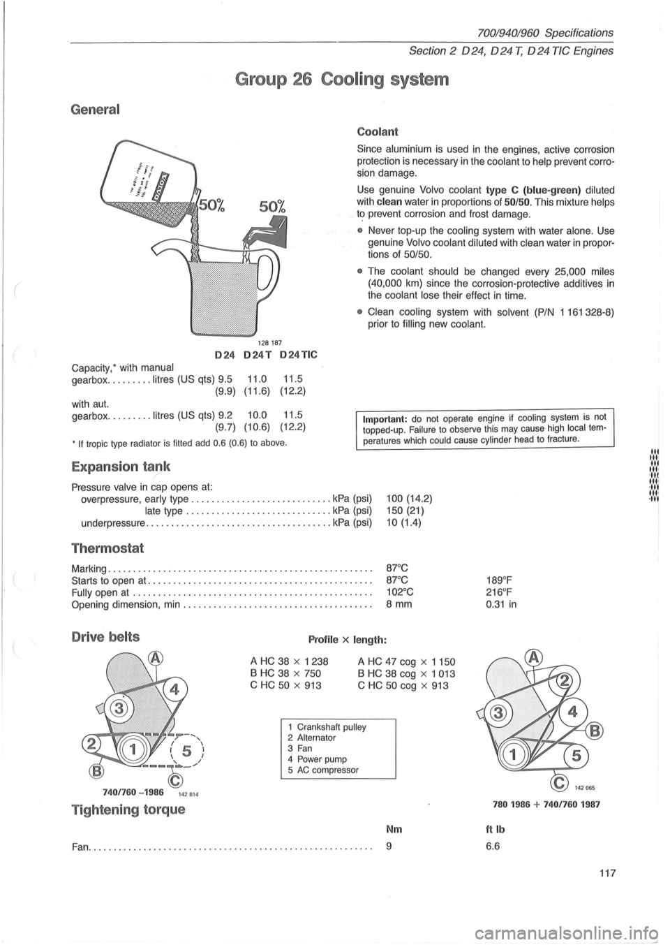
Drive belts Profile x length:
100 (14.2)
150 (21)
10(1.4)
87°C
87 °C
102°C
8 mm
A HC 38 x 1238
B HC 38 x 750
C HC
50 x 913
A HC 47 cog x 1 150
B HC 38 cog x 1 013
C
HC 50 cog x 913
--, / , I 5 I 1 I
--~_/
7401760 -1986 142814
Tightening torque
1 Crankshaft pulley 2 Alternator 3 Fan 4 Power pump
5 AC compressor
Nm
Fan.......................... ............................... 9
189°F
216 °F
0 .
31 in
780 1986 + 7401760 1987
ftlb
6.6
117
lit til' lit ,", ·111 11,1 ·111 1111 ,11'
--'