1982 VOLVO 700 steering
[x] Cancel search: steeringPage 3 of 168
(
)
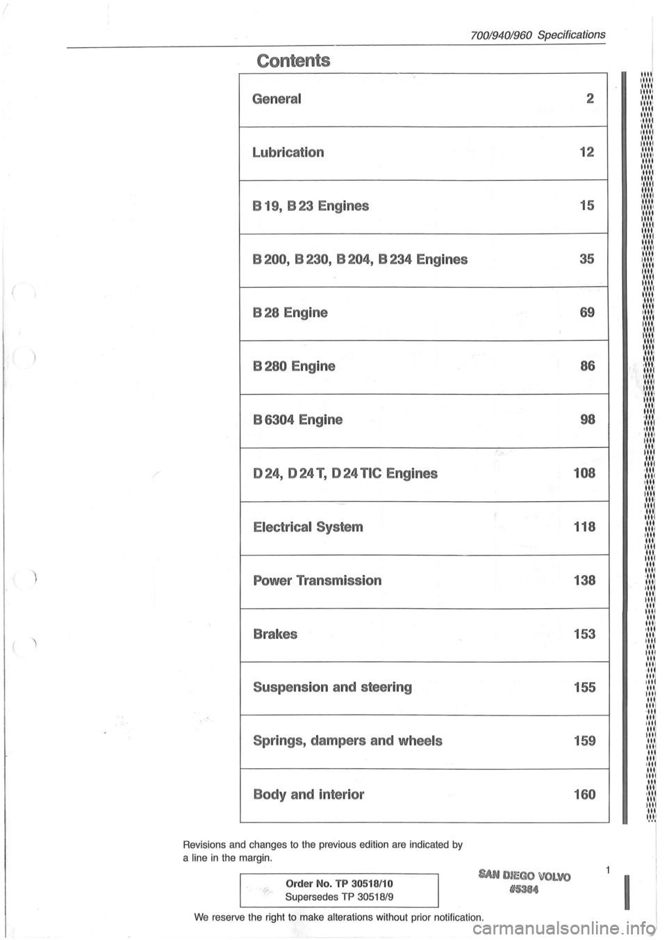
Contents
General
Lubrication B 19, B 23 Engines
B200, B230, B204, B234 Engines
B28 Engine
B280 Engine
B
6304 Engine
024, 024 T , 024 TIC Engines
Electrical System
Power Transmission
Brakes
Suspension and steering
Springs , dampers and
wheels
Body and interior
Revisions and changes to the previous edition are indicated by
a
line in the margin.
Order No. TP 30518/10
Supersedes TP 30518/9
70019401960 Specifications
'., ..
SAN DIEGO ~OLVO
tI5384
2
12
15
35
69 86
98
108
118
138
153 155
159
160
We reserve the right to make alterations without prior notification.
11111 1 1111 1111 IIII! 1111
11111 1111 1111 ·1111 1111 11111 1111 11111 1111 11111 1111 1111 1111
;::::::: 1111 1,1 ..... 1111 II,' ....
~:,:,:,: 1111 , ...... 1
1,' .... 1
1 ...... 1 1111 ·11" 1111 ,II', 1111 III'
I:':':':
'"' '"' ~ .... ,'. 1111 , .... " 1 III' 1111
:I:':',~ ·11 11,1
,"' 1111 III'
'" 1111 ...... 1 ,11' "'1 ,II'
"" I .... I~ III
"' "' ·111 1111 ,III
"' I II I
'" 1111
"' 1111
·11' 1111 I II 1 III III 11 .... 1 III 111/ ,II til. '"I III 1111 .'.'111 ,III 111/ ,II
11.'.'1
Itt'.'1
' llt
lit 'II It.'I'1 It.'.'1 III IItl 'II~ III III til "'1 " " , .... 11
'~I~'~
Page 9 of 168
(
Carburettor
Fuel pump
Clutch
Alternator ,
Steering box
SU
Pierburg
Solex Pierburg
Bosch
AC- oelco
Sofabex
Fichtel & Sachs
Verto/Valeo
Bosch
Cam Gear
Zahnrad Fabrik (ZF)
~
'?' .'" ... .
.
---
" .. u.·.. ,
2
3
5
2
3
4
5
2
3
1
2
3
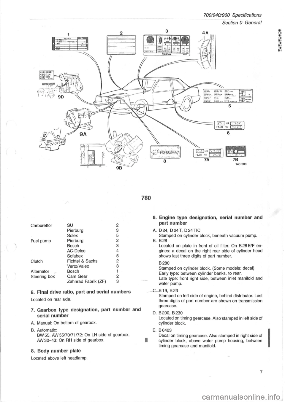
6 . Fina l drive ratio , part and seria l numbers
Located on rear axle .
7. Gearbox type des ig nation, part numbe r and
serial num ber
A. Manual : On bottom of gearbox .
B. Automatic:
BW 55,
AW 55/70171 /72: On LH side of gearbox.
AW3Q-43:
On RH side of gearbox.
8 . Body number pla te
Located above left head lamp.
780
70019401960 Specifications
Section
0 General
3
6
8
7 B 143980
9. Engine type des ig nation, serial number an d
part number
A. 024, o24T, o24TIC
Stamped on cylinder block, beneath vacuum pump.
B. B28
Located on plate in front of oil filter . On B 28 ElF en
gines: a
decal on the right rear side of cylinder head
shows
last three digits of part number.
B280
Stamped on cylinder block. (Some models: decal)
Early
type : between cylinder banks, to rear.
Late type: front right side, between
inlet manifold and
water pump.
__ -G.-819, B 23
I
Stamped on left side of engine, behind distributor. Last
three digits of part number are shown
on transmission
gearcase.
O. B 200, B 230
Located on timing gearcase . Also stamped in left side of
cylinder block.
E. B6403
Decal
on timing gearcase. Also stamped in right side of
cylinder block, above water pump housing , between
timing gearcase and
manifold.
7
I
J
Page 10 of 168
70019401960 Specifications
Section 0 General
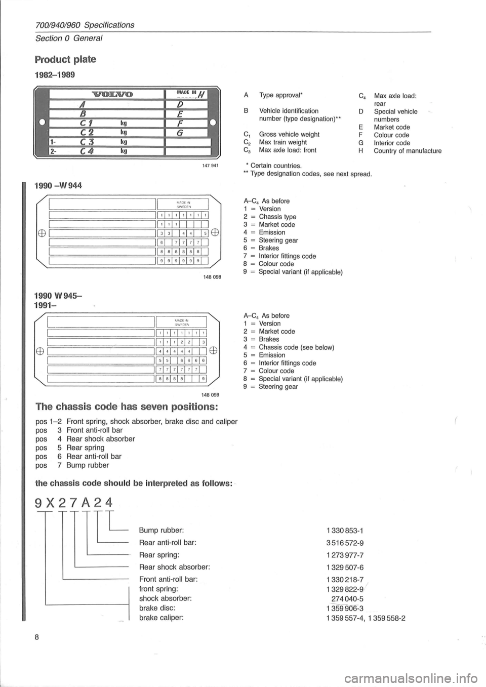
Product plate
1982-1 989
A Type approval *
B Vehicle identification
number (type designation) **
C
1 Gross vehicle weight
C
2 Max train weight Ca Max axle load: front C
4 Max axle
load: rear
D Special vehicle
numbers
E Market code
F
Colour code
G Interior code
H Country of manufacture
147941 * Certain countries.
199 0 -W 944
II '. 1.'DE Irl ~========:~===;:=:::;::;W::::,::::EW'::;:::::=r== ;==============ill, , , ,I, ,1'1 II' , , I I EEl ~===========;II 3 3 + El EEl
;==============ill 6 7 71 7 7 1 I II a a a al a al I ~===================; 11999919911
1 99 0 W 945-
199 1-
[ '.11'10E III S I.'/ FD E"I
148098
,I, ,1,1,1,1,1
EEl ~I ======== I
,I, ,I 21 21 I 31
41441414 1 I IEEl
515 161616161
71 7 7 1 71 71 71 I
Iiaia alai I 191
14 8099
The chass is code~has seven positions :
pos 1-2 Front spring, shock absorber, brake disc and caliper
pas 3 Front anti -roll bar
pas 4 Rear shock absorber
pas 5 Rear spring
pas 6 Rear anti -roll bar
pas 7 Bump rubber
the ch ass is code sh ould be inte rp reted as follow s: ~
9X27A24
E
8
Bump rubber:
Rear
anti -roll bar:
Rear spring:
Rear shock absorber:
Front
anti -roll bar:
front spring:
shock absorber:
brake disc:
brake
caliper:
** T ype designation codes, see next spread.
A-C4 As before
1 = Version
2 = Chassis type
3 = Market code
4 = Emission
5 = Steering gear
6 = Brakes
7 = Interior fittings code
8 = Colour code
9 = Special variant (if applicable)
A-C4 As before
1 = Version
2 = Market code
3 = Brakes
4
= Chassis code (see below) 5 = Emission
6 = Interior fittings code
7 = Colour code
8 = Special variant (if applicable) 9 = Steering gear
1330853 -1
3516572 -9
1273977-7
1329507 -6
1330218 -7
1329822-9 I
2 74040 -5
1359906 -3
1359557-4, 1359558- 2
(
Page 16 of 168
70019401960 Specifications
Section 1 Service and maintenance
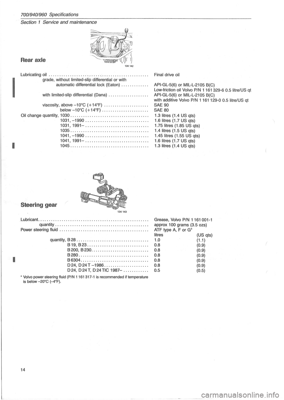
Rear axle
134142
Lubricating oil ............................................... .
grade , without limited-slip differential or with
automatic differential lock (Eaton)
............ .
I with limited-slip differential (Dana) .................. .
viscosity , above
- 10 °C (+14°F) ............ ........ .
below
- 10 °C (+14°F) ............ ........ ..
Oil change quantity, 1030 .................................... .
1031, -1990 ............................. .
1031, 1991-.... ......................... .
1035 .................................... .
1041, -1990 .... ......... " .............. .
I
1041, 1991-............................. .
1045 .................................... .
Steering gear
134143
.Lubricant. .................................................. .
quantity
..................... ........ .. ............ .
Power steering fluid .
....................... ................. .
quantity,
828 ................................. .
819,823 ...................... ...... .
8200,8230 .... ...................... .
8280 ................................ .
I 86304 .......... ....... .............. .
D 24, D 24 T
-1986 .................... .
D24,
D24 T, D24 TIC 1987-. .......... .
* Volvo power steering fluid (PIN 1161 317-1 is recommended if temperature
is below -20°C (-4°F).
14 Final
drive oil
API-GL-5(6) or MIL-L-21 05 8(C)
Low -friction oil Volvo
PIN 1161 329-6 0 .5 litrelUS qt
API-GL-5(6) or MIL-L-2105 8(C)
with additive Volvo
PIN 1161129-00.5 litre/US qt
SAE
90
SAE 80
1.3 litres (1.4 US qts)
1.6 litres (1.7 US qts)
1 .75
litres (1.85 US qts)
1.4 litres (1.5 US qts)
1.45 litres (1.55
US qts)
1.6 litres (1.7 US qts)
1 .3 litres (1.4
US qts)
Grease, Volvo
PIN 1161 001-1
approx 100 grams (3.5 ozs)
ATF type
A, F or G*
litres
1.0
0 .8
0.8
0.8
0.8
0.8
0.5
(US qts)
(1.1 )
(0.9)
(0.9)
(0.9)
(0.9)
(0.9)
(0.5)
Page 135 of 168
(
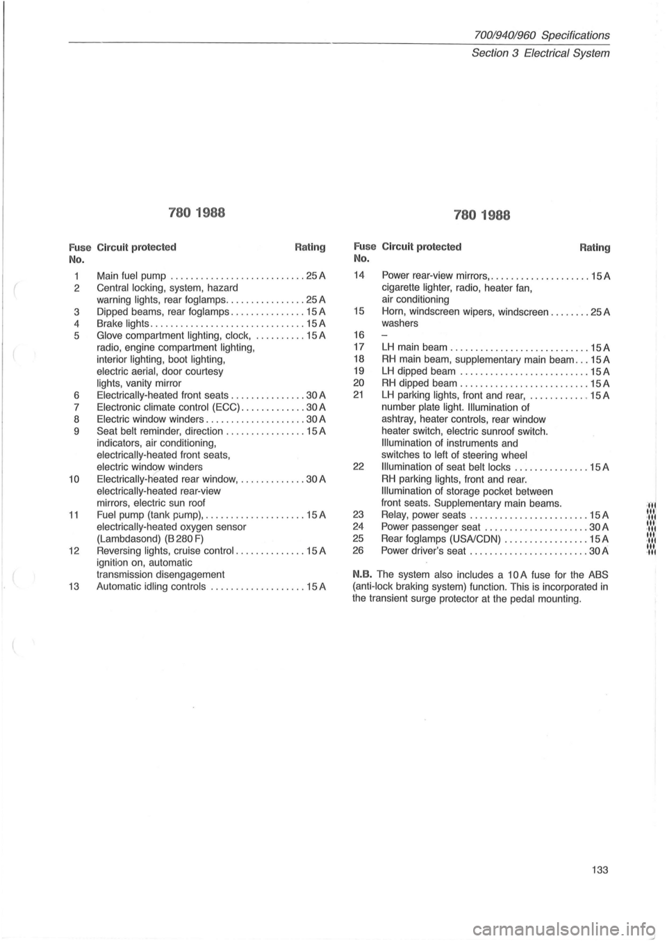
780 1988
Fu se Circuit protected
No.
Rating
1 Main fuel pump ........................... 25 A
2
Central locking, system, hazard
warning
lights, rear fog lamps ................ 25 A
3 Dipped beams, rear
foglamps ............... 15 A
4 Brake
lights .................. ............. 15 A
5
Glove compartment lighting, clock, .......... 15 A
radio, engine compartment
lighting,
interior lighting, boot lighting,
electric aerial,
door courtesy
lights, vanity mirror
6
Electrically-heated front seats ............... 30 A
7
Electronic climate control (ECC) ............. 30 A
8
Electric window winders .................... 30 A
9
Seat belt reminder , direction ................ 15 A
indicators, air conditioning ,
electrically-heated front seats,
electric window winders
10 Electrically-heated rear window, ............. 30 A
electrically -heated rear-view
mirrors,
electric sun roof
11 Fuel pump (tank pi.Jmp), .................... 15 A
electrically-heated oxygen sensor
(Lambdasond)
(B 280 F)
12 Reversing lights, cruise control .. ............ 15 A
ignition on, automatic
transmission disengagement
13 Automatic idling controls ................... 15 A
70019401960 Specifications
Section
3 Electrical System
780 1988
Fu se Circuit protected
No. Rating
14 Power rear-view mirrors, .................... 15 A
cigarette
lighter, radio, heater fan,
air conditioning
15 Horn, windscreen wipers, windscreen ........ 25A
washers
16
17
LH main beam ............................ 15A
18 RH main beam , supplementary main beam ... 15 A
19 LH dipped beam ............. ............. 15A
20 RH dipped beam .......................... 15 A
21 LH parking lights, front and rear, ............ 15 A
number
plate light. Illumination of
ashtray, heater
controls, rear window
heater switch,
electric sunroof switch.
Illumination of instruments and
switches to
left of steering wheel
22 Illumination of seat belt locks ............... 15 A
RH parking lights, front and rear.
Illumination of storage pocket between
front seats.
Supplementary main beams .
23 Relay, power seats ................ .... .... 15 A
24 Power passenger seat .................. ... 30 A
25 Rear fog lamps (USA/CON) ................. 15 A
26 Power driver's seat ................... .. .. . 30 A
N.B. The system also includes a 10 A fuse for the ABS
(anti-lock
braking system) function. This is incorporated in
the transient surge protector at the pedal mounting.
133
·,f' "'I .", '" .",
'" .",
'" .",
Page 136 of 168
70019401960 Specifications
Section
3 Electrical System
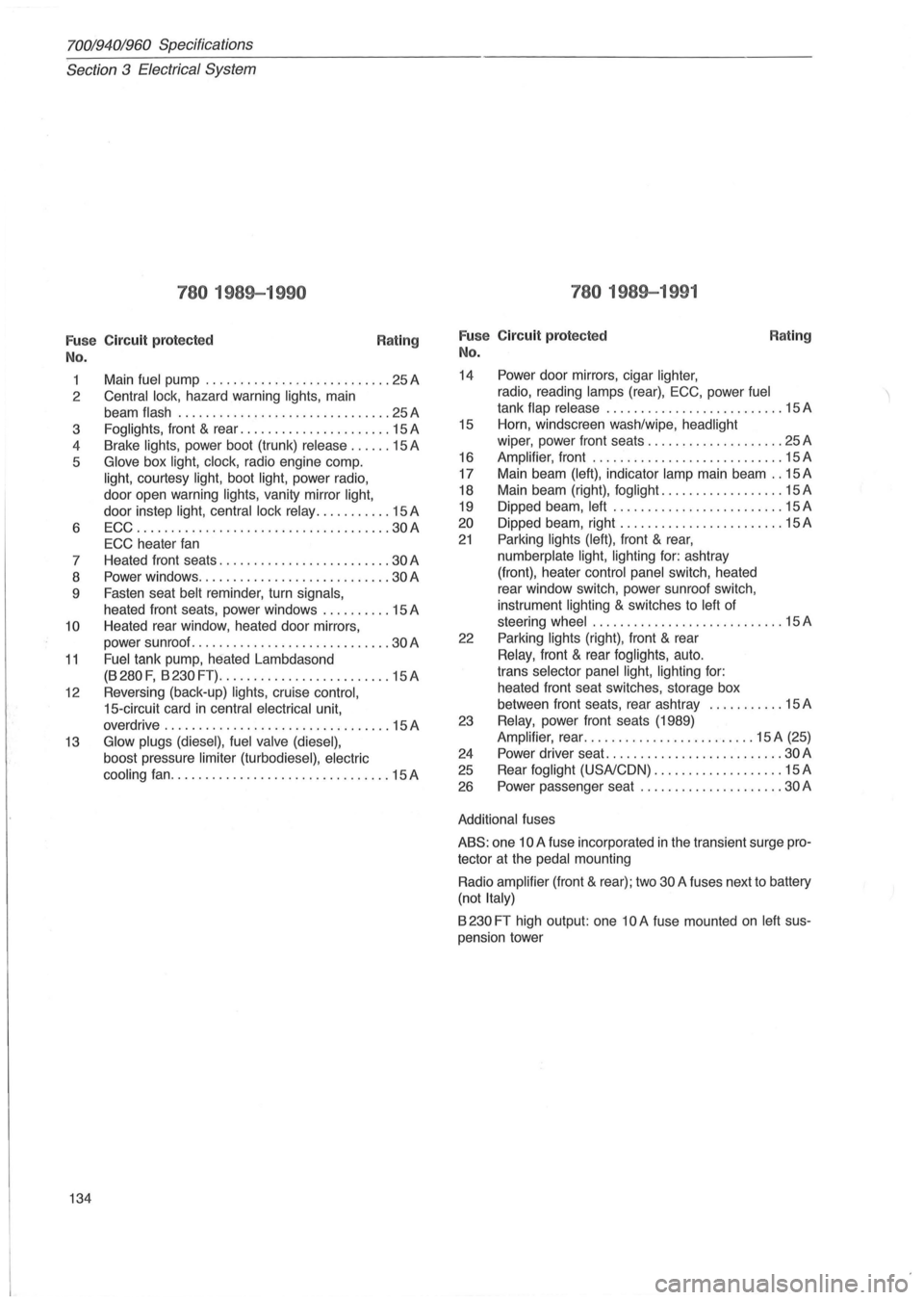
780 1989-1990
Fuse Circuit protected
No. Rating
1
2
3
4
5
6 7
8
9
10
11
12
13
134 Main
fuel pump ........
. .................. 25 A
Central lock, hazard warning lights, main
beam
flash ....... ........................ 25 A
Foglights, front & rear ...................... 15 A
Brake
lights, power boot (trunk) release ...... 15 A
Glove box light, clock, radio engine compo
light, courtesy light, boot light, power radio,
door open warning
lights, vanity mirror light,
door instep light, central lock relay ........... 15 A
ECC
..................................... 30A
ECC heater fan
Heated front seats
......................... 30 A
Power windows
............................ 30A
Fasten seat belt reminder , turn signals,
heated front seats, power windows .......... 15 A
Heated rear window, heated door mirrors,
power sunroof
.............. ............... 30 A
Fuel tank pump, heated Lambdasond
(B 280 F, B 230 FT) ......................... 15 A
Reversing (back-up)
lights, cruise control,
15-circuit card in central electrical unit,
overdrive
.......... ....................... 15 A
Glow plugs (diesel), fuel valve (diesel),
boost pressure limiter (turbodiesel) , electric
cooling
fan ................................ 15A
780 1989-1991
Fuse Circuit protected
No.
14 Power door mirrors, cigar lighter,
radio, reading lamps (rear), ECC, power fuel
Rating
tank flap release .......................... 15 A
15 Horn, windscreen wash/wipe, headlight
wiper, power front seats .... ................ 25 A
16
Amplifier , front ............................ 15 A
17 Main beam
(left), indicator lamp main beam .. 15 A
18 Main beam (right), fog
light. ................. 15 A
19 Dipped beam,
left ......................... 15 A
20 Dipped beam, right .
....................... 15 A
21 Parking lights (left), front & rear,
numberplate light, lighting for: ashtray
(front), heater
control panel switch, heated
rear window switch, power sunroof switch,
instrument
lighting & switches to left of
steering
wheel ...... ...................... 15 A
22 Parking
lights (right), front & rear
Relay, front & rear foglights, auto.
trans
selector panel light, lighting for:
heated front seat switches, storage box
between front seats, rear ashtray
........... 15 A
23
Relay, power front seats (1989)
Amplifier, rear ......................... 15 A (25)
24 Power driver seat
.......................... 30 A
25 Rear
foglight (USA/CON) ................... 15 A
26 Power passenger seat
..................... 30 A
Additional fuses
ABS: one 10 A fuse incorporated in the transient surge pro
tector at the
pedal mounting
Radio
amplifier (front & rear); two 30 A fuses next to battery
(not
Italy)
B 230 FT high output: one 10 A fuse mounted on left sus
pension tower
Page 157 of 168
(
70019401960 Specifications
Section
6 Suspension and steering
Section 6 Front end and steering
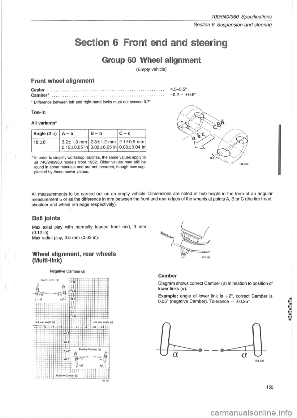
Group 60 Wheel alignment
(Empty vehicle)
Front wheel alignment
Caster ..................................................... 4.5-5.5°
Cambe r*
... ................................... ........ ..... -0.2 -+0.8 °
• Difference between left and right-hand locks must not exceed o.r.
Toe-in
All variant s*
Angle (2 (X) A-a 8-b C-c
18'±8' 3.2±1
.3 mm 2.3±1.2 mm 2 .1 ±0.9 mm
0 .12±0.05 in 0.0 .9±0.05 in 0.08±0.04 in .-
• In order to simplify workshop routines, the same values apply to all 740/940/960 models from 1982. Older values may still be
found in some manuals and are not incorrect, though now supplanted by these newer values.
All measurements to be carried out on an empty vehicle. Dimensions are noted at hub height in the form of an angular
measurement a or as the difference in mm between the front and rear edges of the wheels at points A, B or C (the tire tread,
shoulder and wheel rim edge respective ly).
Ball joints
Max axial play with normally loaded front end, 3 mm
(0.12 in)
Max radial play, 0.5 mm (0.02 in).
Wheel alignment, rear wheels
(
Multi -link )
Negative Camber IfJl
'legall. umb .. 113' -1.0
;l
+
a +a ~ -0.
r;-~ -0.6
P--I I
ii I-i . IT -'. ! . -.1-Un k arm angle (n)
-0
-0
.
Un k a~ angle (a)
-4 -'.-3 "';-2 1 +i +2 + +4 1-
-~~ u ~ 1"'--H---. 1-i-J:-L
_. f-L -\-;-_1_ i-'-1.L?.4 h-
"Lllft~~~~
L.l. f:l+ ~:; +fJ~ .
: I : . : . ill I I I I I m t I " " "! i _ J . ,. . I Positive Camber I~) H 1-1 I I II II ~ t ,I. L LLLu....L1 143 720
Camber
Diagram shows correct Camber (fj) in relation to position of
lower links (a).
Examp le: angle of lower link is +2°, correct Camber is
0 .05 ° (negative Camber). Tolerance = ±0.25°.
143721
155
·ltl III ·ltl It •. ·ltl III ·ltl 'It ·It '
Page 158 of 168
70019401960 Specifications
Section
6 Suspension and steering
A
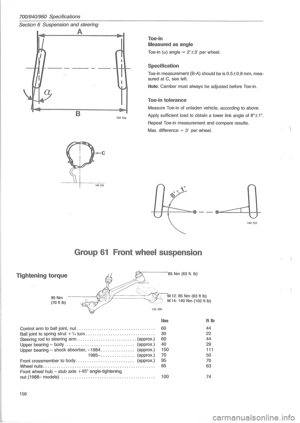
Toe-in
Meas ured as ang le
Toe -in (
Toe-in measurement (B-A) should be is 0.5±0.8 mm, mea
sured at C, see left.
Note: Camber must always be adjusted before Toe-in.
Toe-in tolerance
B 143 724
Measure Toe-in of unladen vehicle, according to above .
Apply sufficient load to obtain a lower link angle of 8°± 1 o .
Repeat Toe-in measurement and compare results.
Max. difference = 3' per wheel.
-c
143723
Group 61 Front wheel suspension
Tightening torque -85 Nm (63 ft. Ib)
95 Nm (70 ft Ib)
~~-.'"
~~======~~C r~M12: 85 Nm (63 ft Ib) ~:./ M 14: 140 Nm (102 ft Ib)
135 398
Nm ft Ib
Control arm to ball joint , nut .................................. . 60 44
Ball joint to spring strut + 1/4 turn .............. ................ . 30 22
Steering rod to steering arm .......................... (approx.) 60 44
Upper bearing -body ............................... (approx.) 40 29
Upper bearing -shock absorber, -1984 ............... (approx .) 150 111
1985- .... ........... (approx.) 70 50
Front crossmember to body. . . . . . . . . . . . . . . . . . . . . . . . . . (approx.) 95 70
Whee l nuts ......... .. ................................ .. ... . . 85 63
Front wheel hub -stub axle +450 angle -tightening
nut
(1988-models) ................................. . ....... . 100 74
156
143 722