1982 FORD SIERRA stop start
[x] Cancel search: stop startPage 14 of 20

washers, and lift the carburettor from the inlet
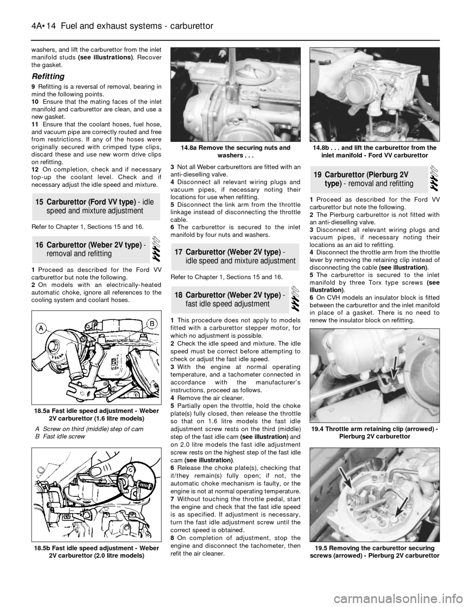
manifold studs (see illustrations). Recover
the gasket.
Refitting
9Refitting is a reversal of removal, bearing in
mind the following points.
10Ensure that the mating faces of the inlet
manifold and carburettor are clean, and use a
new gasket.
11Ensure that the coolant hoses, fuel hose,
and vacuum pipe are correctly routed and free
from restrictions. If any of the hoses were
originally secured with crimped type clips,
discard these and use new worm drive clips
on refitting.
12On completion, check and if necessary
top-up the coolant level. Check and if
necessary adjust the idle speed and mixture.
Refer to Chapter 1, Sections 15 and 16.
1Proceed as described for the Ford VV
carburettor but note the following.
2On models with an electrically-heated
automatic choke, ignore all references to the
cooling system and coolant hoses.3Not all Weber carburettors are fitted with an
anti-dieselling valve.
4Disconnect all relevant wiring plugs and
vacuum pipes, if necessary noting their
locations for use when refitting.
5Disconnect the link arm from the throttle
linkage instead of disconnecting the throttle
cable.
6The carburettor is secured to the inlet
manifold by four nuts and washers.
Refer to Chapter 1, Sections 15 and 16.
1This procedure does not apply to models
fitted with a carburettor stepper motor, for
which no adjustment is possible.
2Check the idle speed and mixture. The idle
speed must be correct before attempting to
check or adjust the fast idle speed.
3With the engine at normal operating
temperature, and a tachometer connected in
accordance with the manufacturer’s
instructions, proceed as follows.
4Remove the air cleaner.
5Partially open the throttle, hold the choke
plate(s) fully closed, then release the throttle
so that on 1.6 litre models the fast idle
adjustment screw rests on the third (middle)
step of the fast idle cam (see illustration)and
on 2.0 litre models the fast idle adjustment
screw rests on the highest step of the fast idle
cam (see illustration).
6Release the choke plate(s), checking that
it/they remain(s) fully open; if not, the
automatic choke mechanism is faulty, or the
engine is not at normal operating temperature.
7Without touching the throttle pedal, start
the engine and check that the fast idle speed
is as specified. If adjustment is necessary,
turn the fast idle adjustment screw until the
correct speed is obtained.
8On completion of adjustment, stop the
engine and disconnect the tachometer, then
refit the air cleaner.1Proceed as described for the Ford VV
carburettor but note the following.
2The Pierburg carburettor is not fitted with
an anti-dieselling valve.
3Disconnect all relevant wiring plugs and
vacuum pipes, if necessary noting their
locations as an aid to refitting.
4Disconnect the throttle arm from the throttle
lever by removing the retaining clip instead of
disconnecting the cable (see illustration).
5The carburettor is secured to the inlet
manifold by three Torx type screws (see
illustration).
6On CVH models an insulator block is fitted
between the carburettor and the inlet manifold
in place of a gasket. There is no need to
renew the insulator block on refitting.
19Carburettor (Pierburg 2V
type) - removal and refitting
18Carburettor (Weber 2V type) -
fast idle speed adjustment
17Carburettor (Weber 2V type) -
idle speed and mixture adjustment16Carburettor (Weber 2V type) -
removal and refitting
15Carburettor (Ford VV type) - idle
speed and mixture adjustment
4A•14Fuel and exhaust systems - carburettor
14.8a Remove the securing nuts and
washers . . .
19.4 Throttle arm retaining clip (arrowed) -
Pierburg 2V carburettor
19.5 Removing the carburettor securing
screws (arrowed) - Pierburg 2V carburettor18.5b Fast idle speed adjustment - Weber
2V carburettor (2.0 litre models)
18.5a Fast idle speed adjustment - Weber
2V carburettor (1.6 litre models)
A Screw on third (middle) step of cam
B Fast idle screw
14.8b . . . and lift the carburettor from the
inlet manifold - Ford VV carburettor
Page 15 of 20

Refer to Chapter 1, Sections 15 and 16.
1Check the idle speed and mixture
adjustment. The idle speed must be correct
before attempting to check or adjust the fast
idle speed.
2With the engine at normal operating
temperature, and a tachometer connected in
accordance with the manufacturer’s
instructions proceed as follows.
3Remove the air cleaner.
4Position the fast idle speed adjustment
screw on the lowest (6th) step of the fast idle
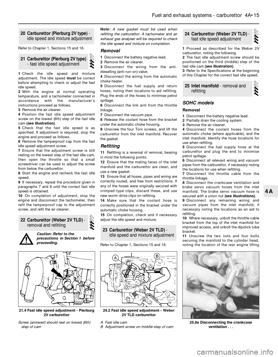
cam (see illustration).
5Check that the fast idle speed is as
specified. If adjustment is required, stop the
engine and proceed as follows.
6Remove the tamperproof cap from the fast
idle speed adjustment screw.
7Ensure that the adjustment screw is still
resting on the lowest step of the fast idle cam,
then open the throttle so that a small
screwdriver can be used to adjust the screw
from below the carburettor.
8Start the engine and recheck the fast idle
speed.
9If necessary, repeat the procedure given in
paragraphs 7 and 8 until the correct fast idle
speed is obtained.
10On completion of adjustment, stop the
engine and disconnect the tachometer, then
refit the tamperproof cap to the adjustment
screw, and refit the air cleaner.Note: A new gasket must be used when
refitting the carburettor. A tachometer and an
exhaust gas analyser will be required to check
the idle speed and mixture on completion.Removal
1Disconnect the battery negative lead.
2Remove the air cleaner.
3Disconnect the wiring from the anti-
dieselling (anti-run-on) valve.
4Disconnect the wiring from the automatic
choke heater.
5Disconnect the fuel supply and return
hoses, noting their locations to aid refitting.
Plug the ends of the hoses to minimise petrol
spillage.
6Disconnect the link arm from the throttle
linkage.
7Disconnect the vacuum pipe.
8Release the coolant hose from the bracket
under the automatic choke housing.
9Unscrew the four Torx screws, and lift the
carburettor from the inlet manifold. Recover
the gasket.
Refitting
11Refitting is a reversal of removal, bearing
in mind the following points.
12Ensure that the mating faces of the inlet
manifold and the carburettor are clean, and
use a new gasket.
13Ensure that all hoses, pipes and wiring are
correctly routed, and free from restrictions. If
any of the hoses were originally secured with
crimped-type clips, discard these, and use
new worm-drive clips on refitting.
14Make sure that the coolant hose is
correctly positioned in the bracket under the
automatic choke housing.
15On completion, check and if necessary
adjust the idle speed and mixture.
Refer to Chapter 1, Sections 15 and 16.1Proceed as described for the Weber 2V
carburettor, noting the following.
2The fast idle adjustment screw should be
positioned on the third (middle) step of the
fast idle cam (see illustration).
3Refer to the Specifications at the beginning
of this Chapter for the correct fast idle speed.
SOHC models
Removal
1Disconnect the battery negative lead.
2Partially drain the cooling system.
3Remove the air cleaner.
4Disconnect the coolant hoses from the
automatic choke (where applicable), and the
inlet manifold. Identify the hose locations for
use when refitting.
5Disconnect the fuel supply hose at the
carburettor and plug the end to minimise
petrol spillage.
6Disconnect all relevant wiring and vacuum
pipes from the carburettor, if necessary noting
the locations for use when refitting.
7Disconnect the throttle cable from the
throttle linkage.
8Disconnect the crankcase ventilation and
brake servo vacuum hoses from the inlet
manifold. The brake servo vacuum hose is
secured with a union nut (see illustrations).
9Disconnect any remaining wiring and
vacuum pipes from the inlet manifold, if
necessary noting the locations as an aid to
refitting.
10Where necessary, unbolt the throttle cable
bracket from the top of the inlet manifold for
improved access, and unbolt the dipstick tube
bracket.
11Unscrew the two nuts and four bolts
securing the manifold to the cylinder head,
noting the location of the rear engine lifting
25Inlet manifold - removal and
refitting
24Carburettor (Weber 2V TLD) -
fast idle speed adjustment
23Carburettor (Weber 2V TLD) -
idle speed and mixture adjustment
22Carburettor (Weber 2V TLD) -
removal and refitting
21Carburettor (Pierburg 2V type)
- fast idle speed adjustment
20Carburettor (Pierburg 2V type) -
idle speed and mixture adjustment
Fuel and exhaust systems - carburettor 4A•15
4A
25.8a Disconnecting the crankcase
ventilation . . .
24.2 Fast idle speed adjustment - Weber
2V TLD carburettor
A Fast idle cam
B Adjustment screw on middle step of cam21.4 Fast idle speed adjustment - Pierburg
2V carburettor
Screw (arrowed) should rest on lowest (6th)
step of cam
Caution: Refer to the
precautions in Section 1 before
proceeding.
Page 18 of 20

9Tighten the manifold securing nuts
progressively to the specified torque, and
similarly tighten the exhaust downpipe
securing nuts. Do not forget to fit the engine
lifting bracket on SOHC models.
10Ensure that the HT leads are reconnected
to their correct cylinders.
Inspection
1The exhaust system should be examined for
leaks, damage, and security at regular
intervals. To do this, apply the handbrake, then
start the engine and allow it to idle. Lie down on
each side of the vehicle in turn and check the
full length of the exhaust system for leaks,
while an assistant temporarily places a wad of
cloth over the tailpipe. If a leak is evident, stop
the engine and use a proprietary repair kit to
seal it. If an excessive leak or damage is
evident, renew the relevant section of the
exhaust system. Check the rubber mountings
for deterioration and renew if necessary.
Removal
2To remove the exhaust system, jack up the
front and rear of the vehicle and support on
axle stands (see “Jacking and Vehicle
Support”).
3If desired, the exhaust downpipe can be
removed independently of the remainder of
the system, and similarly the main part of the
system can be removed, leaving the
downpipe in place.
4To remove the downpipe, unscrew the
securing nuts and disconnect the downpipe
from the manifold. Recover the gasket.
Unscrew the two nuts and bolts, and separate
the downpipe flanged joint from the remainder
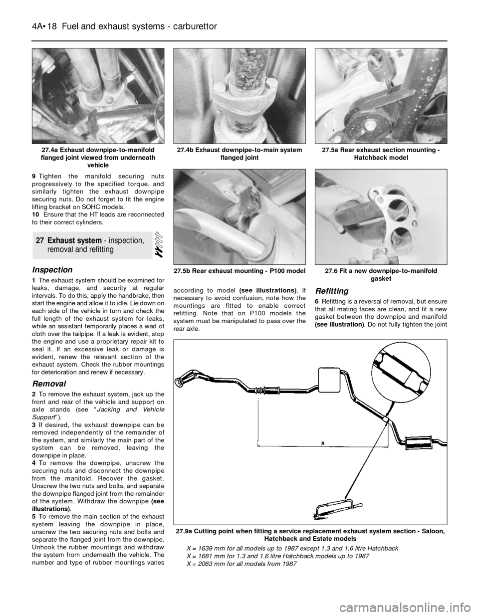
of the system. Withdraw the downpipe (see
illustrations).
5To remove the main section of the exhaust
system leaving the downpipe in place,
unscrew the two securing nuts and bolts and
separate the flanged joint from the downpipe.
Unhook the rubber mountings and withdraw
the system from underneath the vehicle. The
number and type of rubber mountings variesaccording to model (see illustrations). If
necessary to avoid confusion, note how the
mountings are fitted to enable correct
refitting. Note that on P100 models the
system must be manipulated to pass over the
rear axle.
Refitting
6Refitting is a reversal of removal, but ensure
that all mating faces are clean, and fit a new
gasket between the downpipe and manifold
(see illustration). Do not fully tighten the joint
27Exhaust system - inspection,
removal and refitting
4A•18Fuel and exhaust systems - carburettor
27.4a Exhaust downpipe-to-manifold
flanged joint viewed from underneath
vehicle27.5a Rear exhaust section mounting -
Hatchback model
27.9a Cutting point when fitting a service replacement exhaust system section - Saloon,
Hatchback and Estate models
X = 1639 mm for all models up to 1987 except 1.3 and 1.6 litre Hatchback
X = 1681 mm for 1.3 and 1.6 litre Hatchback models up to 1987
X = 2063 mm for all models from 1987
27.6 Fit a new downpipe-to-manifold
gasket27.5b Rear exhaust mounting - P100 model
27.4b Exhaust downpipe-to-main system
flanged joint