Page 11 of 20
Fuel and exhaust systems - carburettor 4A•11
4A
13.4d Exploded view of Weber 2V carburettor - 2.0 litre models from 1985
A Top cover assembly
B Automatic choke assembly
C Automatic choke bi-metal housing
D Secondary idle jet
E Secondary throttle valve vacuum unit
F Stepper motorG Idle mixture screw
H Accelerator pump assembly
J Power valve diaphragm
K Low vacuum enrichment diaphragm
L FloatM Primary emulsion tube
N Primary idle jet
P Needle valve
Q Fuel filter
R Secondary emulsion tube
Page 12 of 20
4A•12Fuel and exhaust systems - carburettor
13.4e Exploded view of Pierburg 2V carburettor
A Automatic choke bi-metal housing
B O-ring
C Automatic choke coolant housing
D Automatic choke vacuum pull-down
unitE Secondary throttle valve vacuum unit
F Idle speed screw
G Accelerator pump diaphragm
H Power valve assembly
K Carburettor bodyL Fuel inlet pipe and filter
M Primary main jet
N Secondary main jet
O Top cover assembly
P Idle jet
Page 13 of 20

Fuel and exhaust systems - carburettor 4A•13
4A
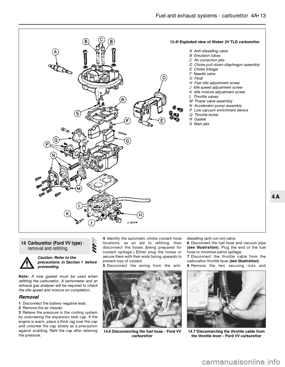
13.4f Exploded view of Weber 2V TLD carburettor
A Anti-dieselling valve
B Emulsion tubes
C Air correction jets
D Choke pull-down diaphragm assembly
E Choke linkage
F Needle valve
G Float
H Fast idle adjustment screw
J Idle speed adjustment screw
K Idle mixture adjustment screw
L Throttle valves
M Power valve assembly
N Accelerator pump assembly
P Low vacuum enrichment device
Q Throttle kicker
R Gasket
S Main jets
Note: A new gasket must be used when
refitting the carburettor. A tachometer and an
exhaust gas analyser will be required to check
the idle speed and mixture on completion.
Removal
1Disconnect the battery negative lead.
2Remove the air cleaner.
3Relieve the pressure in the cooling system
by unscrewing the expansion tank cap. If the
engine is warm, place a thick rag over the cap
and unscrew the cap slowly as a precaution
against scalding. Refit the cap after relieving
the pressure.4Identify the automatic choke coolant hose
locations, as an aid to refitting, then
disconnect the hoses (being prepared for
coolant spillage.) Either plug the hoses or
secure them with their ends facing upwards to
prevent loss of coolant.
5Disconnect the wiring from the anti-dieselling (anti-run-on) valve.
6Disconnect the fuel hose and vacuum pipe
(see illustration). Plug the end of the fuel
hose to minimise petrol spillage.
7Disconnect the throttle cable from the
carburettor throttle lever (see illustration).
8Remove the two securing nuts and
14Carburettor (Ford VV type) -
removal and refitting
14.7 Disconnecting the throttle cable from
the throttle lever - Ford VV carburettor14.6 Disconnecting the fuel hose - Ford VV
carburettor
Caution: Refer to the
precautions in Section 1 before
proceeding.