1981 Citroen CX height
[x] Cancel search: heightPage 258 of 394

Downloaded from www.Manualslib.com manuals search engine 2 OPERATION No MA. 430-O : ~hwki~zg nrtd nrijustittg the suspwrsiott ntd its cotttrol
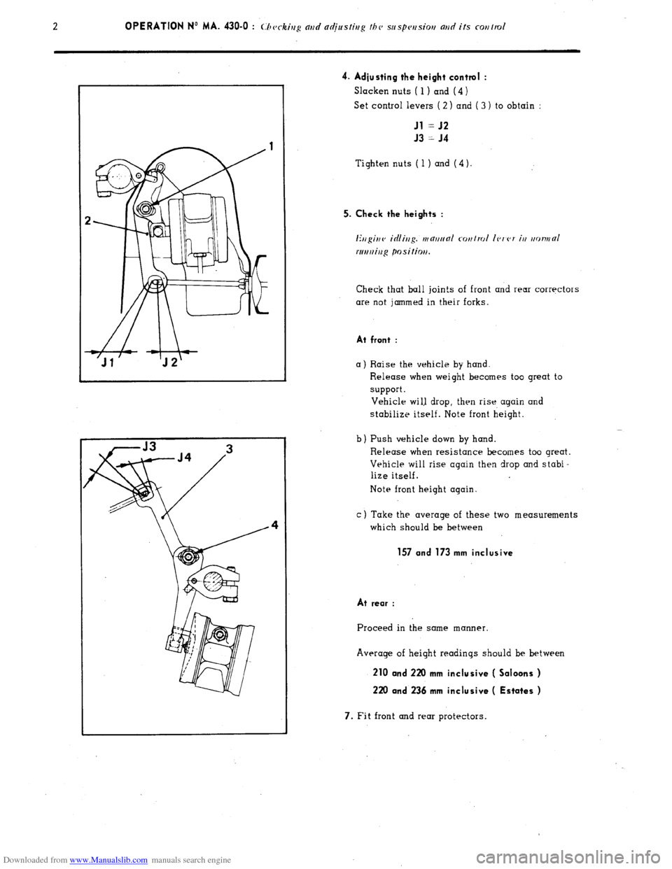
4. Adjusting the height control :
Slacken nuts ( 1) and (4 )
Set control levers ( 2 ) and ( 3 ) to obtain :
Jl = J2
J3 = J4
Tighten nuts ( 1 ) and (4).
5. Check the heights :
Ertgittv icilittg. tttnttt~nl cotttrol Ic,t’c,r itt ttotvttO/
rtrrtttiug positiott.
Check that ball join!s of front and rear corrqctors
are not jammed in their forks.
At front :
a) Raise the vehicle by hand.
b Release when weight becomes too great to
support.
Vehicle wi1.l drop, then rise again and
stabilize itself. Note front height.
Push vehicle down by hand
Release when resistance becomes too great.
Vehicle will rise again then drop and stabi-
lize itself.
Note front height again.
c) Take the average of these two measurements
which should be between
157 and 173 mm inclusive
At rear :
Proceed in the same manner.
Average of height readings should be between
210 and 220 mm inclusive ( Saloons )
220 and 236 mm inclusive ( Estates )
7. Fit front and rear protectors.
Page 283 of 394

Downloaded from www.Manualslib.com manuals search engine Op. MA. 453-O 1
I. BLEEDING THE BRAKES ON SALOON AND ESTATE VEHICLES ( 9/1976- )
A. FRONT BRAKE BLEEDING
NOTE : To avoid emulsifying the fluid
and the
consequent formation of air-pocket in the system,
the circuit should not be under pressure when this
operation is carried out.
1. Release pressure in circuits :
a) Raise front of vehicle (wheels free 1.
b) Slacken pressure regulator bleed screw ( 1 ).
Remove front wheels.
c ) Place CI transparent tube over each bleed
screw (2 ) with its oiher end in CI clean
container.
d) Hold r/on,,,
brake pdnl ar,d loose,, blvcrl
*cr(Iws (2). 2. Bleeding :
(I 1 Start engin’e (idling speed 1 and maintain brake
pedal fully depressed.
b) Tighten pressure regulator bleed screw and
allow fluid to flow until bleed tubes ore
free of air bubbles.
Then tighten bleed screws (2 ).
c) Release broke pedal and remove bleed tubes.
Check the bleed screws for .leaks by depres-
sing brake pedal to fullest extent.
Stop engine.
Fit rubber protectors over the bleed screws.
d 1 Replace front wheels and lower vehicle to
the ground.
B. REAR BRAKE BLEEDING
3. Release pressure in circuits
a) Set monuol height control to lou posi/iou.
b 1 Slacken pressure regulator bleed screw ( 1 )
c) Wait until vehicle has reoched.its lowest
point.
Raise rear of vehicles (wheels free )
Remove lower rear wheel panels and rear
wheels.
d 1 Set manual height control to
hifih positior,
e ) Place Q transparent tube over each bleed
screw with its other end in (I cl&n container.
f ) Open bleed screws (3 ) and depress broke
pedal to fullest extent. 4. Bleeding :
(I) Tighten regulator bleed screw ( 1 1.
Slur/ w?@nr, holding broke pedal depressed.
b) Allow fluid to flow until no bubbles appear
in tube.
Then tighten the bleed screws.
Release brake pedal.
c ) Remove tubes. Check the bleed screws for
leaks by depressing the bloke pedal to
fullest extent. I
Fit rubber protectors.
Stop engine.
5. Refit rear wheels and detachable panels.
Lower vehicle to ground.
Page 284 of 394

Downloaded from www.Manualslib.com manuals search engine 2 OPERATION N” MA. 453-O : (./ ‘cc ,,,g md ndjaslisg I/w hsdrmlir hrnkr rev/m/
k.
II. BLEEDING THE BRAKES ON ESTA ,TE VEHICLES (- 0 ,970 )
A. BLEEDING THE FRONT BRAKES AND THE AIR
CHAMBER ( 1)
NOTE
This bleeding must be carried out with no
pressure in the system
in order to avoid any emul-
sifying of the liquid. and consequently the possible
formation of air bubbles in the system.
1. Release pressure in the system :
a 1 Raise front of vehicle ( wheels free ).
b ) Slacken release screw (3 ) on $ressure requlo-
tor. Remove the front wheels.
c 1 Place on each bleed screw ( 4 1 a transparent
tube wi!h its other end in a clean container
d ) ,Mnir,lnh, brnk L p&d /u//y d<~pwss,~d. and
slacken bleed screws (4 ).
e) Remove air chamber ( 1). Place a transparent
tube on the end of pipe (2 ).
2.
Bleed the br.kes :
a) S/or/ ~v,gir,c,. C id/ivg spevd I md vrnialni,r
hrnk L firdnl. tullr d,~pwss<~d
b) Tighten release screw on pressure regulator.
and let fluid flow until there are no more air
bubbles in the bleed tubes.
Then tighten the bleed screws.
c) Release broke pedo1, and remove bleed tubes.
d) I:;/ nir rhnmhrr ( I ) nltcr hnr~htg /dorm i/
Ibrouph I, i/h Nmp IPSS ?,I nir.
e ) Check bleed screws and air chamber ( 1) are
properly sealed
by fully depressing brake pedal.
Stop engine. Place rubber protective caps over
bleed screws.
f 1 Fit front wheels and lower vehicle to the ground
B. BLEEDING THE REAR BRAKES
3.
Bleed the rear brakes :
a 1 Raise rear of vehicle ( wheels free ).
Remove removable panels and rear wheels.
b) Place manual height control lever in c high
posi~im H ( Release screw on pressure regula-
tor tightened 1.
c) Place on each bleed screw ( 5) a transparent
tube with its other end in a clean container.
Slacken bleed screws (5).
d) nlfliuiniv broke pcdfll ~yrrlly depwssvd. ar,d s/or,
vspiuv C idiivg sprcd ).
e) Let fluid flow until it is free of air bubbles.
Then tighten bleed screws.
Release brake pedal.
f ) Remove bleed tubes.
Check bleed screws are propeily sealed by
fully depressing broke pedal.
Fit rubber protective cops.
Stop engine.
4. Fit rear wheels and removable panels
Lower vehicle to the ground.
Page 285 of 394

Downloaded from www.Manualslib.com manuals search engine OPERATION No MA. 453=0 : Ch J k’ ( c zng and adjjusfing thr hydraulk brake rontrol Op. MA. 453-O 3
III. CHECKING BRAKE PEDAL FREE PLAY
1 st Fitting 2nd Fitting
1 5 111 (I I /‘)7-t __t i%
+ 1. Turn screw ( 1 ) to obtain a clearance of
s
E
(( J )) ~~ 0.05 to 3 mm
-ii Tighten lock-nut ( 2 ).
2 2. Ch k’ ec Ing operation of brake pedal :
a) Release pressure in system.
Set manual height control to /or! /~~.s\‘itio~/
Slacken pressure regulator bleed screw.
( I/ Ill<, I <~/liClC~ is /ill1 rl i, ill, N I~tYlk~~ n~-rllrlll,Inlo,~. nc/un/1 II?<, /I< r/al.
hnke nr c111uu/n/0,. ).
b) Depress pedal three or four times to move the control slide valve to the end of its stroke, and ensure that
pedal returns freely to its stop.
There should be no variation of clearance o J )) as initially set.
Tighten pressure regulator bleed screw.
IV. ADJUSTING THE STOPLAMP SWITCH
1.
Check adjustment of free play on brake pedal ( see above ).
2. Adiusting the stoplamp
The stoplamps must light as soon as the pedal contacts the brake valve.
Bend support plate u a )) of the switch in order to achieve this condition.
Page 358 of 394

Downloaded from www.Manualslib.com manuals search engine OPERATION No MA. 540-O : (hcrking and diusfing the hradlmnps. Op. MA. 540.0 1 ADJUSTING THE HEADLAMPS USING A << REGLOSCOPE >> OR I< REGLOLUX n TYPE APPARATUS
I. CONDITIONS FOR ADJUSTMENT
With the vehicle empty and in running order :
a) Ensure that the tyre ore correctly inflated
and heights correctly adjusted.
Place vehicle on CI flat level surface.
Run the engine at idling speed and set manual.
height control to normal running position.
1 Place the instrument on the same level as that
of the vehicle and opposite the headlamp to be
adjusted. 2. ADJUSTMENT
Horizontal adiustment
Switch on the dipped headlamps.
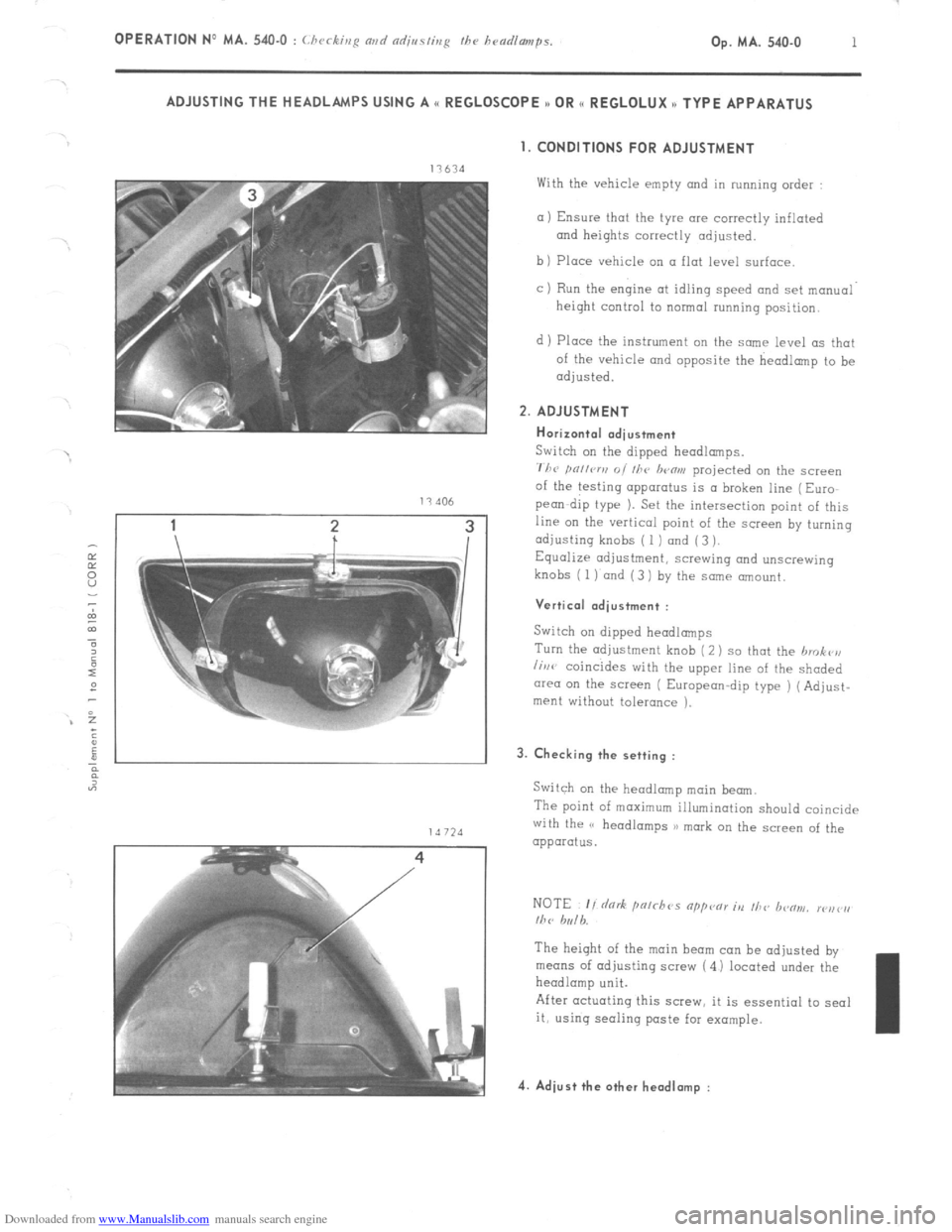
711~ pn,lcrv 01 111~ lwflrn projected on the screen
of the testing apparatus is a broken line (Euro
pea-dip type 1. Set the intersection point of this
line on the vertical point of the screen by turning
adjusting knobs ( 1 ) and (3 ).
Equalize adjustment, screwing and unscrewing
knobs (
1) and (3 1 by the same amount.
Vertical .dius+ment :
Switch on dipped headlamps
Turn the adjustment knob (2) so that the hrokr’n
lirw coincides with the upper line of the shaded
cwea on the screen ( European-dip type ) (Adjust-
ment without tolerance ). 3. Checking the setting :
Switch on the headlamp main beam.
The point of maximum illumination should coincide
with the (’ headlamps 3) mark on the screen of the
apparatus.
The height of the main beam can be adjusted by
means of adjusting screw (4 1 located under the
headlamp unit.
After actuating this screw, it is essential to seal
it, using seoling paste far example. 4. Adiust the other headlamp :
Page 361 of 394

Downloaded from www.Manualslib.com manuals search engine AIR-CONDITIONING
CHARACTERISTICS AND SPECIAL FEATURES OF THE AIR-CONDITIONING SYSTEM
The air-conditioning system includes the refrigeration and the heating of the air drawn into the passenger compart-
ment. REFRIGERATION
This allows the air in the passenger compartment to be cooled, while at the same time reducing its dampness (and
therefore the misting up of the glass ) HEATING
It is of the (( FROID - 15)) or (( FROID - 20 )) type
1 The air is blown around the channels of a radiator supplied by water from the engine cooling system.
&
co
5
3
t
E REFRIGERATION
E I. CHARACTERISTICS
ASPERA FRIGO type HG 700 or
Compressor
1 .
SANKYO * type SD 508
De-watering tank . SINGER
Condenser _.. ._..: _._...... . . . . . . . . . . . CHAUSSON
Evaporator-blower , SOFICA
Flexible hoses ..,_.,....,............................................................................... STRATOFLEX and RANCO
Refrigerating fluid . R. 12 Weight
of refrigerating fluid _..._.._._._..,_..__.................................................... 1 kg ( 2.2 lbs )
Oil for lubricating compressor TOTAL LUNARIA 25 or SUNISO No. 5
or TEXACO CAPELLA (( E )) grade 500
Quantity of oil for lubricating compressor ,
280 g i.e. a height of 21 to 29 mm
f
CJSCC,~~ ior SANKYO UIVI~WSSO~ J
* Only fitted on vehicles fitted with converter and air-conditioning option.
Page 384 of 394

Downloaded from www.Manualslib.com manuals search engine OPERATION No MA. 841-O : Adjusting fh~ doors Op. MA. 841-O 1 I. ADJUSTING A FRONT DOOR
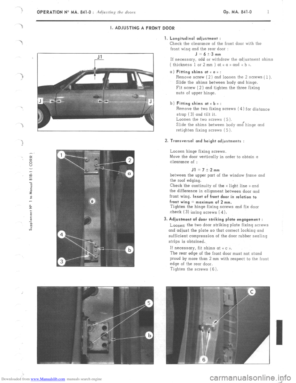
1. Longitudinal adiustment :
Check
the clearance of the front door with the
front wing and the rear door : J=6+_3mm
If necessary. add or withdraw the adjustment shims
( thickness 1 or 2 mm ) at <( a 1) and << b to_ a) Fitting shims at SC a u :
Remove screw (2) and loosen the 2 screws ( 1).
Slide the shims between hody and hinge.
Fit screw (2) and tighten the three fixing
nuts of upper hinge.
b) Fitting shims at <, b n :
Remove the two fixing screws (4) for distance
strop (3) and tilt it.
Loosen the two screws (5 ).
Slide the shims between body &hinge and
retighten fixing screws (5 ). 2. Transversal and height adjustments :
Loosen hinge fixing screws.
Move the door vertically in order to obtain a
clearance of : Jl = 7 +‘2mm
between the upper port of the window frame and
the roof edging.
Check ‘the continuity of the a light line 1) and
the difference in alignment between door and
front wing. Inset of front door in relation to
front wing = maximum of 2 mm.
Tighten the hinge fixing SCWNS and fix door
check (3) using screws (“4). 3. Adjustment of door striking plate engagement :
Loosen. the two door striking plate fixing screws
and adjust the plate so that correct locking and
sufficient compression of the door rubber sealing
strips is obtained.
If necessary, fit shims at (cc )P.
The rear edge of the front door must not stand
proud by more than 2 mm with respect to the front
edge of the rear door.
Tighten the screws (6 ).
Page 385 of 394

Downloaded from www.Manualslib.com manuals search engine 2 OPERATION NO MA. 841-O : Adjmfing /he o’r,ors
II. ADJUSTING A REAR DOOR
1. Longitudinal adjustment :
Check the clearonce of the rear door with the
rear wing and with the front door :
J =6+~3mm
If necessary, fit Suitable shims ( of thickness 1 or
2 mm ) at points (( a N and (( b )).
a) Fitting shims at point II a * :
Remove screw ( 1) ond loosen screws (2).
Slide in at point I< a D under hinge the shim or
shims required.
Fix scr&v (2 ).and tighten the three hinge
fixing screws.
b)
Fitting shims at point e b u :
Remove distance strop fixing screws and pivot
it, around its axis.
Loosen the two hinge fixing screws (4).
Slide shims under hinge at point <, b >j.
Re-tighten fixing screws (4 1.
2. Transversal and height adjustments :
Check clearance between upper edge of window
frmne and
edqe of roof :
Jl =7+~2mm
Check also continuity of the G light line x
and the recess
of the rear door in relation ta
the front door : 2 mm max.
Loosen upper and lower hinge fixing screws.
Adjust door to obtain positioning (IS above.
Tighten fixing screws of these hinges.
Secure distance strap by its two screws (3)
3. Adjustment of striking plate engagement :
Loosen striking plate fixing screws (3) and adjust so as
to obtain correct locking of door and sufficient
compression of the rubber sealing strips.
If necessary, fit adjustment spacers at point o c u.
Check recess
of rear wing in relation ta rear
dwr : 2 mm max.
4: Position window-winder handle to obtain an angle.
of W = approximately 30’ when the window is
closed.