Page 136 of 394
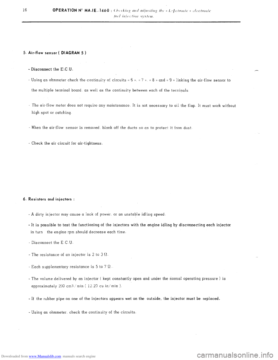
Downloaded from www.Manualslib.com manuals search engine 5. Air-flow sensor ( DIAGRAM 5 )
- Disconnect the E.C.U.
- Using an ohmmeter check the continuity of circuits (( 6 )a, H 7 )) (( 8 H and (( 9 )) linking the air-flow sensor to
the multiple terminal board. as well as the continuity between each of the terminals
- The air-flow meter does not require any maintenance. It is not necessary to oil the flop. It must work without
high spot or catching
When the air-flow sensor is removed blank off the ducts so OS to protect it from dust
- Check the air circuit for air-tightness.
6. Resistors and injectors :
- A dirty injector may cause o lock of power. or on unstable idling speed.
- It is possible to test the functioning of the injectors with the engine idling by disconnecting each injector
in turn the engine rpm should decrease each time.
- Disconnect the E C U
- The resistance of an injector is 2 to 3 II.
- Each supplementary resistance is 5 to 7 R
- The volume delivered by an injector ( kept constantly open and under the normal operating pressure ) is
approximately 200 cm3 /min ( 12 25 cu in/min )-
- If the rubber pipe on one of the injectors appears wet on the outside, the injector must be replaced.
- Using an ohmmeter, check the continuity of the circuits
Page 140 of 394
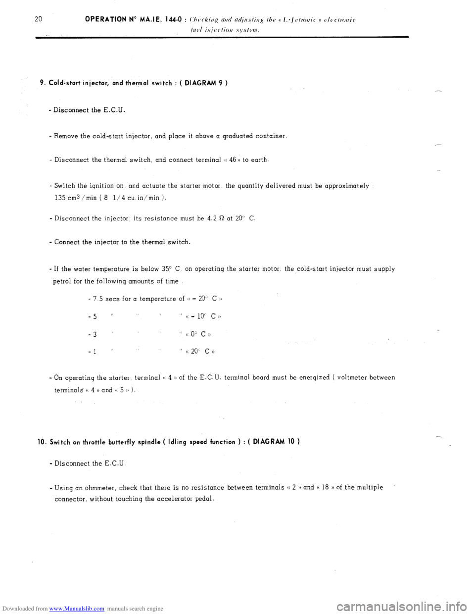
Downloaded from www.Manualslib.com manuals search engine 9. Cold-start injector, and thermal switch : ( DIAGRAM 9 )
- Disconnect the E.C.U.
- Remove the cold-start injector, and place it above a graduated container.
- Disconnect the thermal switch, and connect terminal (( 46 )) to earth
- Switch the ignition on and actuate the starter motor. the quantity delivered must be approximately
135 cm3 /min ( 8 l/4 cuin’min 1.
- Disconnect the injector: its resistance must be 4.2 Q at 20” C
- Connect the injector to the thermal switch.
- If the water temperature is below 35” C, on operating the starter motor, the cold-start injector must supply
petrol for the followinq amounts of time
- 7.5 sets for a temperature of (( - 20” C ))
-5 ” ” (( - 10“ c N
-3
” cc 0: c ))
-1 ” ” (( 20” c >)
- On operating the starter. terminal (( 4 )) of the E.C.U. terminal board must be enerqized ( voltmeter between
terminals (( 4 )) and 0 5 )) 1.
10. Switch on throttle butterfly spindle ( Idling speed function ) : ( DIAGRAM 10 )
- Disconnect the E.C.U
- Using an ohmmeter, check that there is no resistance between terminals N 2 H and (( 18 H of the multiple
connector, without touching the accelerator pedal.
Page 143 of 394
Downloaded from www.Manualslib.com manuals search engine 11. Switch on throttle butterfly spindle ( maximum power function ) ( DIAGRAM 11 )
- Disconnect the E.C.U.
- Using a battery operated ohmmeter, check there is no resistance between terminals (( 3 H and (( 18 )) of the
multiple connector board, with the accelerator pedal fully depressed
t 12. E.C.U. : ( DIAGRAM 12) +
s
*
i :
2 - Visually check the condition of the terminals ( male connectors on the E-C U., and female connectors
on the multiple connector socket ).
- With the engine running, tap lightly on the E.C.U., to detect any possible defect in the soldering ( dry
joints ).
Page 145 of 394
Downloaded from www.Manualslib.com manuals search engine OPERATION No MA.IE. 144-0 : (,hcrkir~g m/cl nrl;tts/ir/<~ I/W a I.-J~~/m,i~ ~~otectrot,ic Op. MA.IE. 144-O 25 fi~cl irijection systc~rti.
ANNEXE : A - CHECKING THE IGNITION
THE ENGINE TURNS, BUT DOES
NOT FIRE
Page 147 of 394
Downloaded from www.Manualslib.com manuals search engine ANNEXE : B - CHECKING THE AIR CIRCUIT
L __- -’
Page 148 of 394
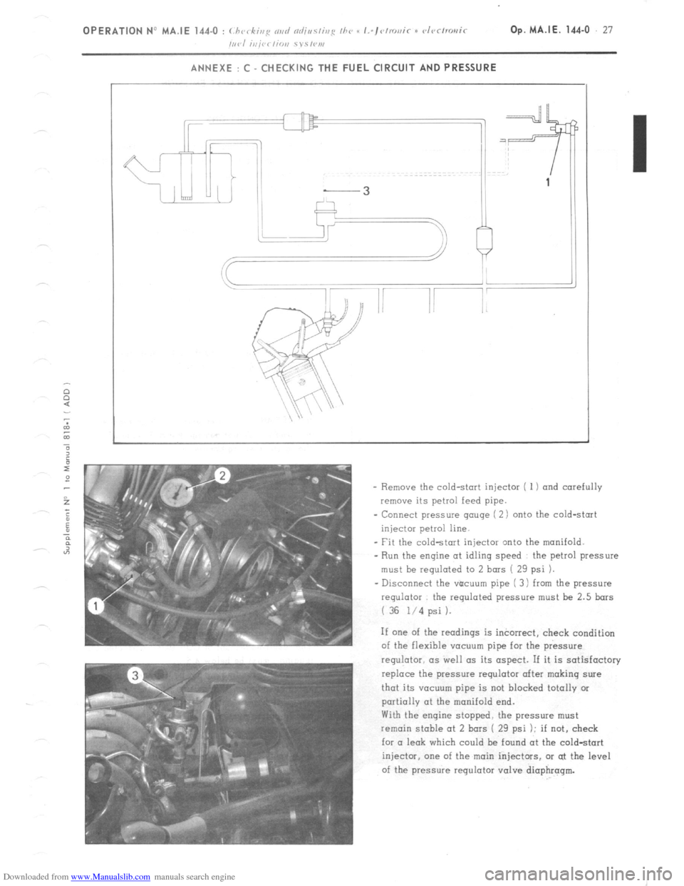
Downloaded from www.Manualslib.com manuals search engine ANNEXE : C CHECKING THE FUEL CIRCUIT AND PRESSURE
- Remove the cold-start injector ( 1) and carefully
remove its petrol feed pipe.
- Connect pressure gauge ( 2) onto the cold-start
injector petrol line.
- Fit the cold-start injector zmto the manifold.
- Run the engine at idling speed the petrol pressure
must be regulated to 2 bars ( 29 psi ).
- Disconnect the vticuum pipe ( 3 i from the pressure
regulator the regulated pressure must be 2.5 bars
i 36 l/4 psi ).
If one of the readings is incorrect, check condition
of the flexible vacuum pipe for the pressure
regulator. as well as its aspect. If it is satisfactory
replace the pressure requlotor after making sure
that its VCICUU~ pipe is not blocked totally or
partially at the manifold end.
With the engine stopped, the pressure must
remain stable at 2 bars ( 23 psi ); if not, check
for a leak which could be found at the cold-start
injector, one of the main injectors. or at the level
of the pressure regulator valve diaphragm.
Page 149 of 394
Downloaded from www.Manualslib.com manuals search engine 28 OPERATION N” MA.IE. 144-O : Ch <,c ,ng n,,d nlfjusfiup Ihe u I.-~<~tro,,ir i) <~lrr/mr,ir k’
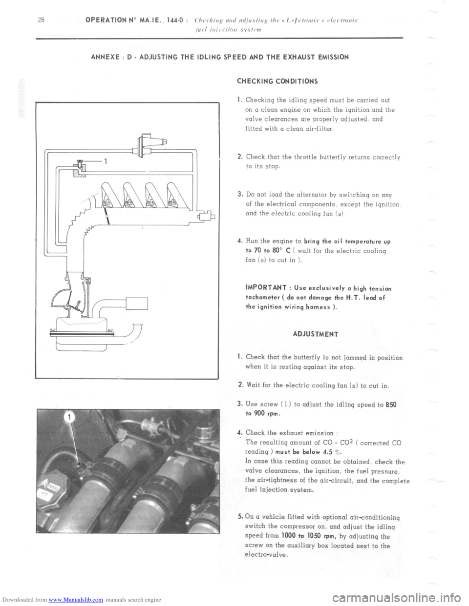
/,,,.I i,,jrr/io,, S~S,W1, ANNEXE : D - ADJUSTING THE IDLING SPEED AND THE EXHAUST EMISSION
CHECKING CONDITIONS
1.
Checking the idling speed must be carried out
on a clean engine on which the ignition and the
valve clearances are properly adjusted and
fitted with a clean air-filter.
2. Check that the throttle butterfly returns correctly
to its stop.
3. Do not load the alternator by switching an any
of the electrical components, except the iqnition
and the electric cooling fan (s) 4.
Run the engine to bring the oil temperature up
to 70 +o 80’ C ( wait for the electric cooling
fan is) to cut in ). IMPORTANT : Use exclusively (I high tension
tachometer ( do not damage the H.T. lead of
the ignition wiring harness ).
ADJUSTMENT
1. Check that the butterfly is not jammed in position
when it is resting against its stop.
2. Wait for the electric cooling fan (s) to cut in.
3. Use screw ( 1 ) to adjust the idling speed to 850
to 900 rpm.
4. Check the exhaust emission :
The resulting amount of CO - CO2 ( corrected CO
reading 1 must be beI& 4.5 %.
In case this reading cannot be obtained, check the
valve clearances, the ignition, the fuel pressure,
the air-tightness of the aircircuit, and the complete
fuel injection system.
5. On (I vehicle fitted with optional oirtonditioning
switch the compressor on, and adjust the idling
speed from 1000 to 1050
rpm, by adjusting the
screw on the auxiliary box located next to the
electro-vol”e.
Page 150 of 394
Downloaded from www.Manualslib.com manuals search engine OPERATION No MA. 173-O : Chrrkivp fhr prmd s,,pp/> Op. MA. 173.0 1
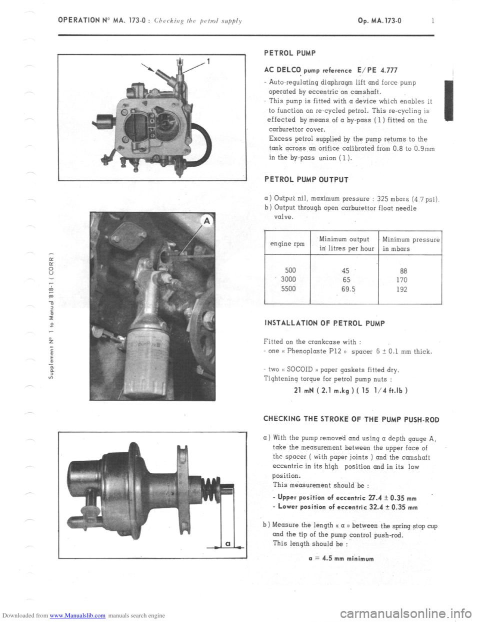
PETROL PUMP
AC DELCO pump reference E/PE 4.777
Auto-regulating diaphragm lift and force pump
operated by eccentric on camshaft.
This pump is fitted with (I device which enables it
to function on re-cycled petrol. This re-cycling is
effected by means of a by-pass .( 1 ) fitted on the
carburettor cover.
Excess petrol supplied by the pump returns to the
tank across an orifice calibrated from 0.8 to 0.9mm
in the by-pass union (1).
PETROL PUMP OUTPUT
(I) Otitput nil, maximum pressure : 325 mbars (4 7 psi).
b) Output through open carburettor float needle
valve.
500 45 88
3000 65 170
5500 69.5 192
I I
Minimum pressure
in mbors
INSTALLATION OF PETROL PUMP
Fitted on the crankcase with :
one (( Phenoploste P12 )) spacer 5 + 0.1 mm thick.
two (< SOCOID a> paper gaskets fitted dry.
Tightening torque for petrol pump nuts :
21 mN ( 2.1 m.kg ).( 15 l/4 ft.lb )
CHECKING THE STROKE OF THE PUMP PUSH-ROD
a) With the pump removed and using (I depth gouge A,
take the measurement between the upper face of
the spacer ( with paper joints ) and the camshaft
eccentric in its high position and in its low
position.
This measurement should be :
- Upper position of eccentric 27.4 ? 0.35 mm
- Lower position of eccentric 32.4 rk 0.35 mm
b) Measure the length u a a) between the spring stop cup
and the tip of the pump control push-rod.
This length should be :
a = 4.5 mm minimum