1980 SKODA 120 LSE height
[x] Cancel search: heightPage 70 of 238

Turn
the flonge
on the centering
orbor so thot
the longer, cylindricol port
foces the clutch,
push it ogoinst the friction plote
hub, ond olign
the ends of the levers to touch the flonge.
A deviotion from the ploneness
of 0.1 mm
is
permissible. Use feeler gouges for checking
this deviotion.
lf it is not possible
to odiust the out-trovel of
the clutch releose levers to o volue given
by the
length of the flonge cylindricol port
due to
excessive weor
of the friction plote, odiust to
the next higher volue.
Clinch nuts on the
odiusting nuts bocked off up to the end of the
threod ore o worning of o weor limit which pre-
cludes ony further odiustment
of the clutch.
4. After hoving reossembled
the engine with
o new or odiusted clutch,
check ond, if necess-
ory, odiust the cleoronce between the releose
levers ond the throw-out beoring -
see Chop-
ter 15.4.
3.3 CLUTCH DISMANTLING
Owing to its simplicity,
it is not necessory
to
describe in detoil the dismontling
of the clutch,
but some speciol feotures
deserve ottention.
1. lf the friction plote
ond clutch cover ore
intended to be re-used, mork their relotive
positions using centre punch
morks to preserve
the originol bolonce of the ossembly.
2. To dismontle
the clutch, it is
necessory to
compress the clutch cover to relieve the stress
of the releose lever bolts. For this purpose
use
the MP 2-101
ossembly plote
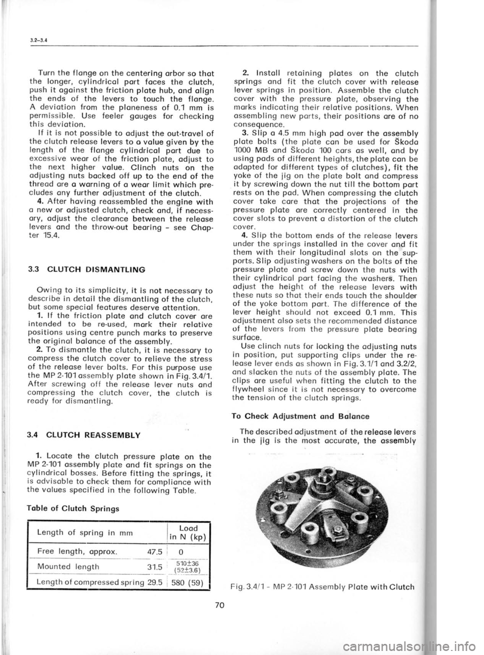
shown in Fig.3.4/1.
After screwing off the releose lever nuts ond
compressing the clutch cover,
the clutch is
reody for dismontling.
3.4 CLUTCH REASSEMBLY
1. Locote
the clutch pressure
plote
on the
MP 2-101
ossembly plote
ond fit springs
on the
cylindricol bosses. Before fitting
the springs, it
is odvisoble to check them for
complionce with
the volues specified
in the following Toble.
Toble of Clutch Springs
Lood
Length of spring in mm
lin -rrr"ltp1
Mounted length
31.55'10+36
(s2t3.6)
Length of compressed spring 29.5
I 580 (59) 2.
Instoll retoining plotes
on the clutch
springs ond fit the clutch cover with releose
lever springs in position.
Assemble the clutch
cover with the pressure plote,
observing the
morks indicoting their relotive positions.
When
ossembling new pot'ts,
their positions
ore of no
consequence.
3. Slip o 4.5 mm high pod
over the ossembly
plote bolts (the
plote
con be used
for Skodo
1000 MB ond Skodo 100 cors os well,
ond by
using pods
of different heights, the plote
con be
odopted for different
types of clutches), fit the
yoke of the
iig on
the plote
bolt ond compress
it by screwing down the nut till the bottom port
rests on the pod.
When compressing the clutch
cover toke core thot the projections
of the
pressure plote
ore correctly centered in
the
cover slots to prevent
o distortion of the clutch
cover.
4. Slip the bottom ends of the releose levers
under the springs instolled in the cover ond fit
them with their longitudinol
slots on the sup-
ports. Slip odiusting woshers on the bolts of the
pressure plote ond screw down the nuts with
their cylindricol port
focing the woshers. Then
odjust the height of the releose levers with
these nuts so thot their ends touch the shoulder
of the yoke
bottom port.
The difference of the
lever height should not exceed 0.'l mm. This
odiustment olso sets the recommended
distonce
of the levers from the pressure
plote
beoring
surfoce.
Use clinch nuts for locking the odiusting nuts
in position,
put
supporting clips under the re-
leose f ever ends os shown in Fig.3.111 ond3.212,
ond slocken the nuts of the ossembly plote.
The
clips ore useful when fitting the clutch to the
f lywheel since it is not necessory to overcome
the tension of the clutch springs.
To Check Adiustment ond Bolance
The described od justment
of the releose levers
in the
iig is
the most occurote, the ossembly Fig.3
Dim
plote be
simulotin
For on<
porogropl
The cl
with the
friction ;
ports of '
clutch on
To bol
centering
pressure
the chips
lf thesr
boloncing ing holes
in o circk
4mmofr
between
fostening
3.5 FR|C
lf the f
it is odvi
8.5 mm th
When r
the frictio
ond only r
complicot
After hr
the plote
if necessc
recheckinl
quired.
70 Fig.3.4l1
-
IAP 2lol
Assembly Plote with Clutch
Page 121 of 238

(
t
t
s r
1
S
t S
n
o
fl
p
t\
e
g
tl
St
T
o
e
ir
h,
el
r€
re
5. Ploce
the steering
box with its bottom
boll
beoring resting on the MP 7-102 jig
ond press
the steering screw
with both beorings into the
iig. Extroct the
bottom beoring using
the MP
6-111 king pin
socket remover
ond push
the
steening screw with the top beoring oert of the
steering box. Support the beoring by the Mp
7-102 iig crnd
press
it out.
7.3 REASSEMBLING STEERING BOX
1. Press the dust cup with its seoling
ring
into the steering
box with the pressed-in
bush
ofter hoving thorouchly
cleorred the box. Now
pf oce the box on the MP 7-102
iig oncl
press-in
the bottom boll beorinct
using tlrei pressing
mandrel MP 7-103.
2. Fit the lower beoring
cop seoled
off with
o poper
gcsket
ond seoling compound, slip
lpring woshers
on to the bolts,
ond tighten the
bolts with o torque os per
Chopter t.6. f it the
wosher on the steering screw
with its deflec-
tion focing
the screw threod ond press
the
top beoring on the screw
using the Mp Z-103
pressing mondrel.
3. Then ploce
ogoin the steering box on the
MP7-102 iig ond
press
into it ond into the bot-
tom beoring the steering
screw with the pnessed-
-on top boll beoring,
using ogoin
the Mp7-103
pressing mondrel. For further ossembly, use the
vice ond the dummy brocket.
Fig. 7.311 -
Pressing-in Bottom
Beoring
on MP 7-102
Jig (support
plote)
Using
MP 7-103 Piressinq
Mondrel 4.
Meosure the height of the beoring pro-
truding from the steering box ond odiust it by
fitting shims interspoced with poper goskets
cooted with o seoling
compound.
Fosten down
the cop by tightening the bolts. Check the
steering screw for free rototion
ond the obsence
of ploy.
The beoring should be without o cleor-
once or there hos
to be o prestress
of up to
0.07 mm.
5. Remove the bolts of the cop, slip the rub-
ber seoling ring dipped in oil on to the shoft,
ond fit the dust cup on the cop. lnstoll spring
woshers on the bolts. Should the cup be over-
stroined due to the toleronce
of the recess for
the seoling ring or the ring itself
, instoll
o poper
gosket under it os under tlre ccrp.
6. Locote the steering nut on the screw fol-
lowecl by the rocker shoft with pin, spring,
spring pin, ond the licl gosket
cooted with
o seoling compound, ond fit the lid with bush
in position to close the steering
box. Instoll
spring woshers under the bolts orrd tighten the
bolts with o torque os per
Chopter 1.8. Screw
the set screw into the lid ond rnove
the steer-
ing geor
so thot the drop orrn is swivelled
through obout one holf of its trovel from the one
or the other extreme lock position.
Witlr the
drop ornr in this position,
screw down the set
screw os for os it will go
ond then bock it off
through obout 95 to '120'.
This will provide
for
on odequote cleoronce of the steering geor.
[.ock the set screw in position
with the re-
spective nut.
7. Drive the key on to the rocker shoft cone,
fit the drop orm ond hold it down lightly with
the nut. Clomp the drop orm in o vice, tighten
fully the nut (for
the tightening torque see
Chopter 1.8), ond secure tlre nut with o cotter
pi n.
8. Clomp ogoin the steering box by meons of
the dummy brocket ond moke sure
thot the dnop
orm con swivel from one extreme lock position
to the other. A certoin
resistonce should olwoys
be present,
but if the resistonce is too greot,
decreose it by o slight slockening of the set
screw in the lid. The
rototing resistonce of the
shaft should not exceed 20 Nm (O.2
kpm). Refer to
page 117/118 for testing
procedure.
9. Set the ossembled steering box in its fit-
ting position
(inclined
by obout 40o) ond pour
in oil through the hole in the bbx lid (cover)
till the oil level reoches the bottom edge of the
filling hole. Then
screw down the topered plug.
7.4 RELAY (TDLER)
LEVER
For its instollotion (ond
removing in reverse
order) ond ony pertinent porticulors
see the
Chopter 6.5, porogrophs
2 ond 3.
122
Page 167 of 238

r3.2-t 3.3
tuJ
t(A 4r
3t 2t
,tl
(
Per
lp
5
4
3
2, I
Ah re€
l
i
i
ii Observe
strictly the following instructions:
1. Mointoin the electrolyte level ot the level
of the perforoted
inserts between the plotes
or
so thot the inserts ore
covered with the electro-
lyte to o moximum height
of 4
mm. The
bottom
limit of the electrolyte level is 3 mm below the
perforoted inserts. Use only distilled woter for
topping up the electrolyte. Add electrolyte only
if it hos been obviously spilt from
the bottery.
In such cose, its density must correspond to
the density of the electrolyte Eemoining in the
bottery. 2. Keep the bottery terminols
cleon, remove
oxides occosionolly, ond
coot the terminols
with minerol
ielly.
3. Wipe off the electrolyte spilt
over the bot-
tery surfoce since it is conductlve ond couses
dischorging of the bottery.
4. Check the
chorging of the bottery occord-
ing to
the electrolyte density or check the
voltoge drop using o voltmeter with o looding
resistor ond comporing the obtoined reoding
with on evaluotion toble or scole.
5. When chorging the bottery
outside the cor,
use chorging current volues occording to the
toble. The voltoge should be
controlloble in the
ronge from 12.6 to 16.8
volts. The fully dis-
chorged bottery is fully chorged in obout 13 to
20 hours when
o) the electrolyte ottoins o density of 1.28 in
oll cells ond does not chonge in o period
of
two hours;
b) the cell voltoge (meosured
with opplied cur-
rent) ottoins o volue of 2.6
to 21
volts ond
does not chonge within two hours
of con-
tinued chorging;
c) oll cells ore lively gossing.
6. An olreody used bottery must not be left
without electrolyte or dischorged os it is opt to
suffer from
such o condition.
7. The bottery in on unused cor must
be
removed ond chorged outside the cor
within
three months ot th-e lotest. lf the cor is under
repoir for o prolonged
period,
toke oll necessory
steps to keep the bottery in good
condition.
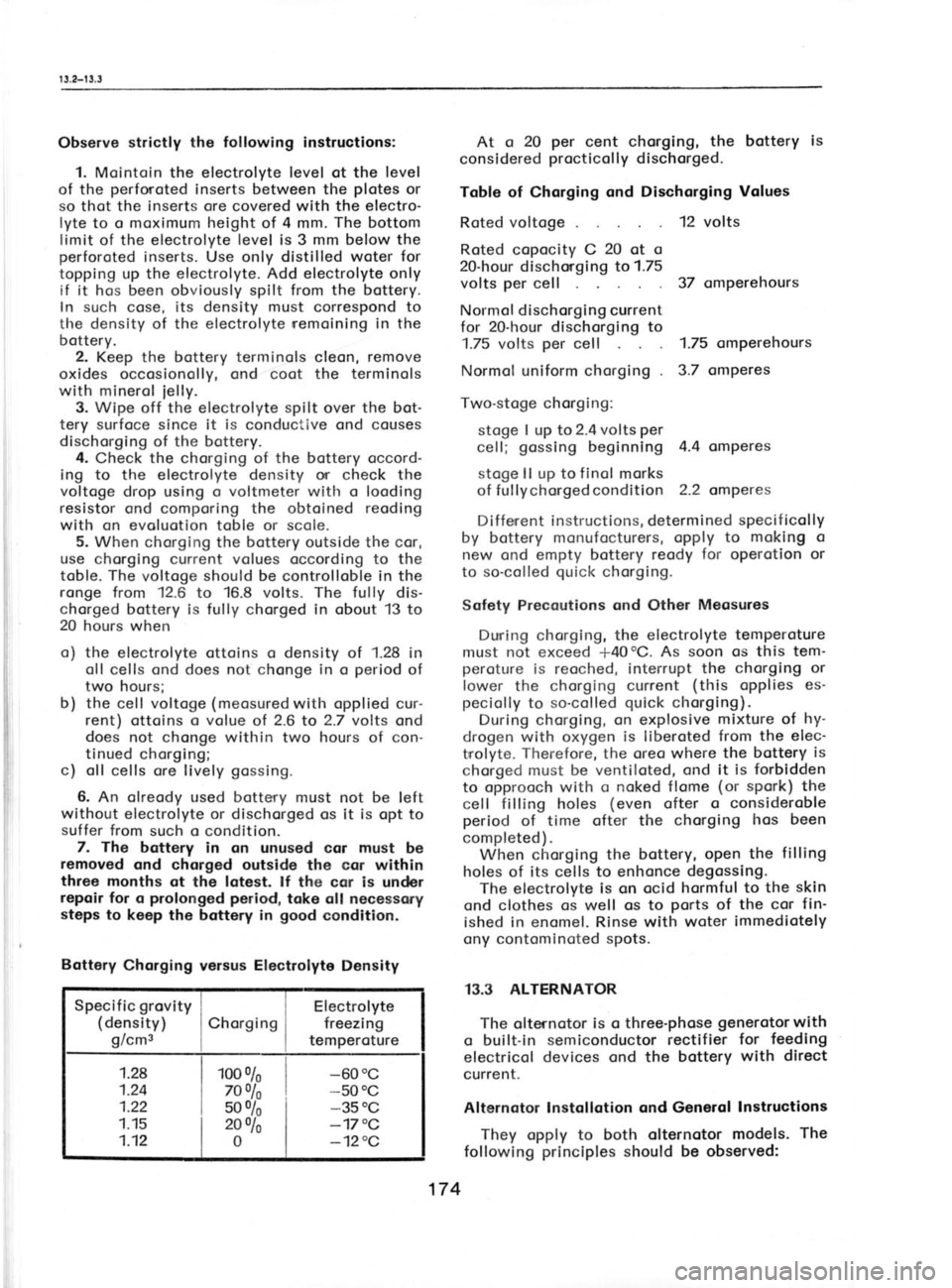
Bottery Chorging versus Electrolyte
Density
Specificgrovityl i Electrolyte
(density) iChorgingl freezing
g/cms I I temperoture
1.28
1.24
1.22
1.15
1.12 1oo
o/o
Toolo s0% 2oolo
0 -60
0c
-50 0c
-35 0C
-17 "C
-120C At o
20 per
cent chorging, the bottery is
considered procticol
ly dischorged.
Toble of Chorging ond Dischorging Values
Roted voltoge 12 volts
Roted copocity C 20
ot o
20-hour dischorging to 1.75
volts per
cell 37 omperehours
Normol dischorging current
for 20-hour
dischorging to
1.75 volts per
cell 1.75 omperehours
Normol uniform chorging 3.7 omperes
Two-stoge chorging:
stoge I up to 2.4 volts per
cell; gossing
beginning 4.4 omperes
stoge ll up
to f inol
morks
of fuf fychorgedcondition 2.2 omperes
Diffenent instructions, determined specificolly
by bottery monufocturers, opply to moking o
new ond empty bottery reody for
operotion or
to so-colled quick
chorging.
Sofety Precoutions ond Other Meosures
During chorging, the electrolyte temperoture
must not exceed +40oC. As soon os this
tem'
peroture is reoched, interrupt the chorging or
lower the chorging current (this
opplies es-
peciolly to so-colled quick
chorging).
During chorging, on explosive mixture of hy-
drogen with oxygen is liberoted from the elec-
trrolyte. Therefore, the oreo where the bottery is
chorged must be ventiloted, ond it is forbidden
to opprooch with o noked flome (or
spork) the
cell filling holes (even
ofter o consideroble
period of time ofter the chorging hos been
completed). When chorging the bottery, open the filling
holes of its cells to enhonce degossing.
The electrolyte is on ocid hormful to the skin
ond clothes os well os to ports
of the cor fin-
ished in
enomel. Rinse with woter immediotely
ony contominoted spots.
13.3 ALTERNATOR The olternotor is o three-phose generotorwith
o built-in semiconductor rectifier
for feeding
electricol devices ond the bottery with
direct
current.
Alternotor lnstollotion ond Generol lnstructions
They opply to both olternotor models. The
following principles
should be observed:
174
Page 175 of 238

I
I
I
s
I
I
I
t
(
(
t
l
,
t
T c
R
L D
v Ir
1' 2
3
orotely
(
screen the other one) . With lef t
directionol heodlomps,
the borderline deviotes
towords the other
side.
lf the heodlomps ore neorer to the woll thon
the soid
5 metres, decreose the meosure indi-
coting the
deviotion of the light ond
dorkness
bordeiline from the
height of the heodlomps
obove the ground in the
direct proportion to
the
decreose of
tfre distonce, for
exomple when
plocing the cor 2.5 metres
from the woll, de-
creose the deviotion bY holf.
Light proiections "A"
ond "B"
correspond to
the spocing of heodlomPs on
the cor ond they
hove the following dimensions:
Heodlomps, dio. 160
mm 1,030
mm
Duol heodlomps, dio.
130 mm 1,114
mm
Auxiliory heodlomps, dio.
130 mm 790 mm
When odjusting the heodlomps, the cor must
be empty ond the
tyres must be correctly in-
floted. Hologen heodlomps should
not be left
switched on for too long o period os they build
up heot if not cooled by heod-on
oir blost when
driving. For lhe odiustment of
heodlomPs ore intended
screws in their fromes. The screws
ore occess'
ible ofter the removol of the side ports
of the
grille. Remove the copscrews of the corners
ond push
the grille
oside.
Heodlomp Assembly
o) The fundomentol fostening
Port of
circulor
heodlomps is the
so-colled support plote
(rec-
tongulor plote)
ottoched to the bodywork by
copscrews with lock woshers. The
heodlomp
housing is bolted to this suPPort plote by bolts
with nuts ond lock woshers. One of the bolts holds
down olso the
lug of the eorthing coble-
The inner frome,
forming the
odiusting element
of the heodlomp insert, is ottoched
to the
hous'
ing by two speciol odiusting screws
ond two
tension springs. The heodlomp insert
is ot'
toched to
the bezel by
three copscrews.
There is one left-hond ond
one right-hond
support plote.
Both should
be mounted with the
oriow ond the word "TOP"
upwords. With
the
exception of the ouxiliory heodlomps, the
heod'
lomp inserts ore different for
the left-hond ond
the right-hond troffic. The leods
enter the hous-
ing through o
rubber grommet.
When r-eplocing the insert, remove
the bezel
copscrews. After
hoving fitted o new insert, it
is necessory to reodiust the
heodlomps.
Front Direction Indicotors
The right-hond ond
left-hond direction indi-
cotors ore undisossembloble units
(the
lomp
fostening sockets (locks) ore
mounted in the
direction towords the cor longitudinol centre
line). They ore fostened to their brockets in the
bumper with o nut ond o ploin ond
o lock
wosher.
Toil Lomp Cluster
The lomp cluster is on undisossembloble unit
fostened to
the bodywork by
nuts with ploin
woshers ond the
respective bolts.
Scrope off
the enomel ot the
top bolt used for holding
down the eorthing coble.
For the sequence
of the individuol lomps ond
their bulbs see Fig. 13.111 ond the respective
porogroph on bulbs.
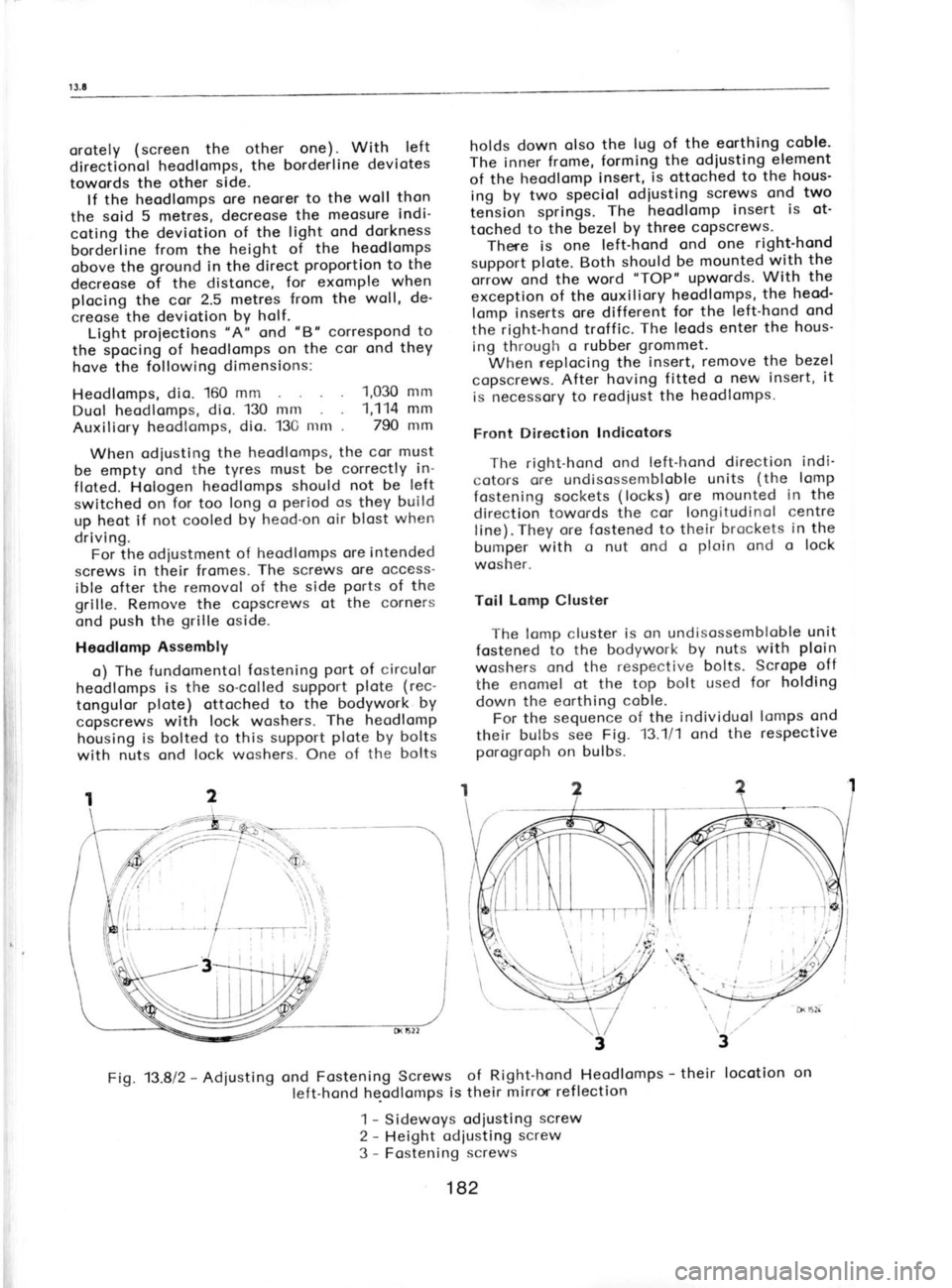
Fig. 13.812 -
Adiusting ond
Fastening Screws of Right-hond Heodlomps -
their locotion
on
left-hond he-odlomps is their
mirror ref lection
1 -
Sidewoys odiusting screw
2 -
Height odiusting screw
3 -
Fostening screws
182
Page 195 of 238

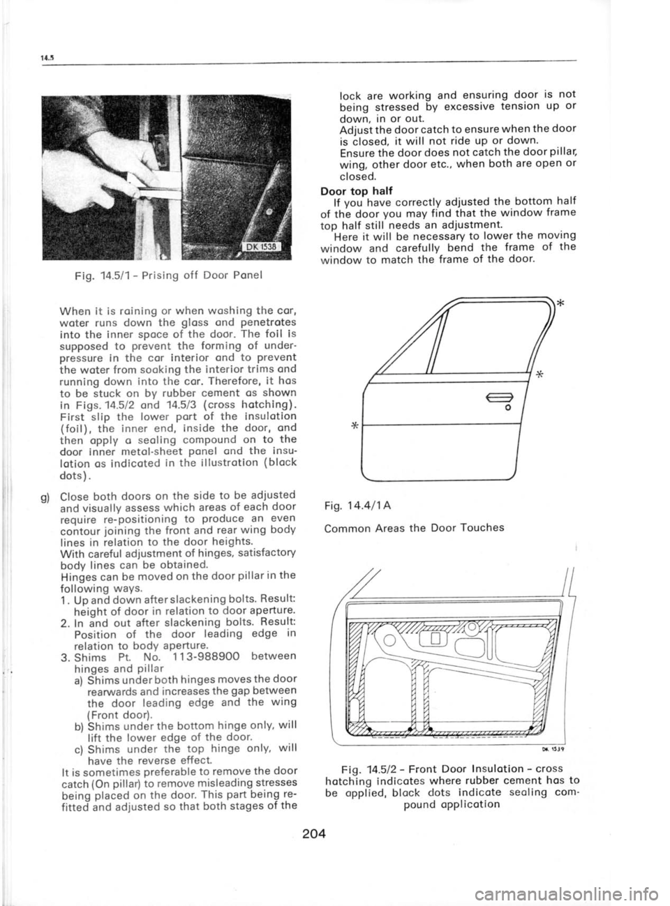
Fig.
M511-
Prising off Door Ponel
When it is roining or when woshing the cor,
woter runs down the gloss
ond penetrotes
into the inner spoce of the door. The
foil is
supposed to prevent
the forming of under-
pressure in the cor interior ond to prevent
the woter from sooking the interior trims ond
running down into the cor. Therefore,
it hos
to be stuck on by rubber cement os shown
in Figs. 14.512 ond 14.5/3 (cross hotching).
First slip the lower port
of the insulotion
(foil), the inner end, inside the door, ond
then opply o seoling compound on to
the
door inner metol-sheet ponel
ond the insu-
lotion os indicoted in the illustrotion (block
dots ) .
Close both doors
on the side to be adjusted
and visually assess which areas of each door
require re-positioning to produce
an even
contour joining
the front and rear
wing body
lines in relation to the door
heights.
With careful adjustment of hinges, satisfactory
body lines
can be obtained.
Hinges can
be moved on the door pillar in
the
following ways.
1 . Up and down after slackening bolts.
Result:
height of door in relation to door ap_erture.
2. In and out after slackening bolts. Result:
Position of
the door leading edge in
relation to bodY aPerture'
3. Shims Pt.
No. 1 13-98B9OO between
hinges and pillar
a) Shims under
both hrnges moves
the door
rearwards and
increases the gap
between
the door leading
edge and the
wing
(Front door).
b) Shims under the bottom hinge
only, will
lift the lower edge
of the door.
c) Shims under the top
hinge only, will
have the reverse effect.
It is
sometimes preferable to remove
the door
catch (On pillar)
to remove misleading stresses
being placed
on the door. This part
being re-
fitted and adjusted so
that both stages of
the lock are
working and
ensuring door is not
being stressed by
excessive tension
up or
down, in or out.
Adjust the door
catch to ensure when
the door
is closed, it will
not ride up or down'
Ensure the door does not catch the door pillar,
wing, other door etc., when both are open or
closed.
Door top half
lf you-have correctly
adjusted the
bottom half
of thb door you
may find that the window frame
top half still needs an adjustment.
Here it will be necessary to
lower the moving
window and carefully bend the
frame of the
window to match the frame
of the door'
Fig. 14.4/14
Common Areas
the Door Touches
Fig. 14.512- Front
Door lnsulotion -
":t;
hotching indicotes where
rubber cement hos to
be opplied, block dots indicote seoling
com'
pound opplicotion
204