1980 SKODA 120 LSE fuel
[x] Cancel search: fuelPage 62 of 238
Choke
-
Cold-storting Device (Fig.2.1916)
Bosicolly, the choke is o self-contoined cor-
burettor consisting of o fuel reservoir, o petrol
jet, on oir
iet, o
vocuum
controller, ond o throttle
volve. The
mixture is formed in the throttle
volve zone where it is sucked
out from under
the corburettor throttle
disc.
At increosing engine speed, the rising vocuum
moves the plunger
of the choke vocuum
control,
the holes in the plunger
overlop ond thus the
mixture is enriched outomoticclly. The driver
controls the richness
of the mixture by opening
or closing the choke throttle volve.
Auxiliory Devices
Vqcuum connection for the vocuum odvonce
control picks
up vocuum (the
underpressure)
obove the throttling disc of stoge
| (see
Fig.
2.1st4).
The suction connecticri is led out of the cor-
burettor lower flonge os o tube from
under the
throttle disc of stoge ll. The
suction prevents
o generotion
of vocuum (underpressure)
in the
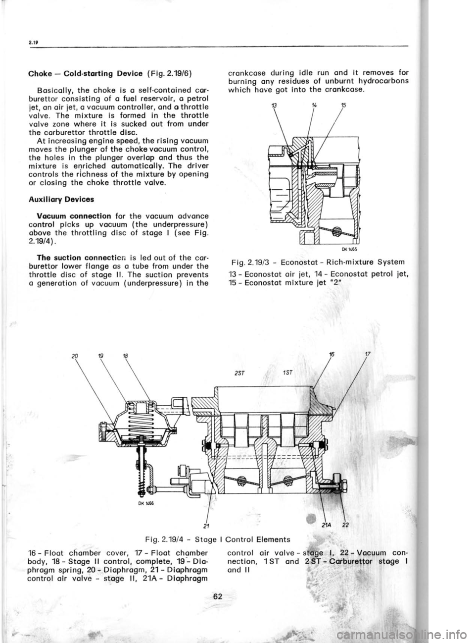
Fi1.2.1914 -
Stoge
16 -
Ff oot
chomber cover, 17 -
Floot chomber
body, 18 -
Stoge ll
control, complete, 19 -
Dio-
phrogm spring, 20 -
Diophrogm, 21- Diophrogm
control oir volve -
stoge ll, 21A -
Diophrogm cronkcose
during idle
run ond it removes for
burning ony residues of unburnt
hydrocorbons
which hove got
into the cronkcose.
Fi1.2.1913 -
Econostot -
Rich-mixture System
13 -
Econostot oir
iet, 14 -
Econostot petrol
iet,
15 -
Econostot mixture
iet "2"
I Control Elements
control oir volve -
sttfge l, 22-
Vocuum con-
nection, 1 ST ond 2
ST -
Corburettor stoge I
ond ll i:lrFig.2.
23 -
Inier
pump, c(
Accelerc
venti ng
I
32 and 3
30 -
Chol
Choke vr
volve
CARBUR
AND RE'
Diogno
rect chec
reossemb
62
Page 64 of 238
I
I
( 1. Excessir
- overfloc
o) leoky n
b) too higl
- incorrec
c) too lorg
d) too sm<
e) oir-ventl
2. lncorrecl
- engine
o) choked
chokedi ncorrec
defectiv
- errotic i
e) portiolly
f) folse oir
l ncorrec
too low
lncorrect i ncorrec
i ncorrec
c) choked
4- Poor occ
chokedleoky no
defectivr
Loss of p
stoge | |
choked ,
domoge<
i ncorrect
stoge | | mutuolly
ond ll in
Engine w
storti ng
choked <
low fuel
i ncorrect
( excessir
o) lf no nera
hold the
connecte
emergen(
Fi1.2.1917
-
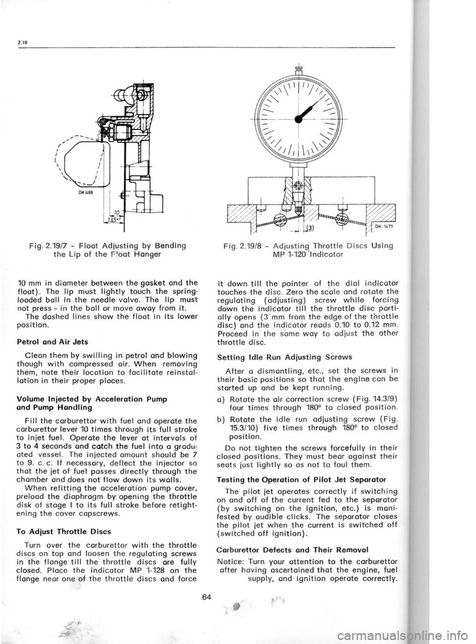
Floot Adjusting by Bending
the Lip of the Floot Honger
10 mm in diometer between the gosket
ond the
floot). The lip must lightly
touch the spring-
looded boll in the needle volve. The lip must
not press -
in the boll
or move owoy from it.
The doshed lines show
the floot in its lower
position.
Petrol and Air
Jets
Cleon them by swilling
in petrol
ond blowing
though with compressed oir. When removing
them, note
their locotion to focilitote reinstol-
lotion in their proper ploces.
Volume Iniected by Accelerotion Pump
ond Pump Hondling
Fill the corburettor with fuel
ond operote the
corburettor lever 10 times through its full stroke
to iniet fuel. Operote the lever ot intervols
of
3 to 4 seconds
ond cotch the fuel into o grodu-
oted vessel. The
iniected omount should be 7
to 9. c. c. lf necessory,
deflect the injector so
thot the
iet of
fuel posses
directly through the
chomber ond does not flow down its
wolls.
When refitting the occelerotion pump
cover,
prelood the diophrogm by opening the throttle
disk of stoge I to its full
stroke before retight-
ening the cover copscrews.
To Adiust Throttle Discs
Turn over the corburettor
with the throttle
discs on top ond loosen the reguloting screws
in the flonge till
the throttle discs ore fully
closed. Ploce the indicotor MP 1-128
on the
flonge necr one of tlre throttle
discs ond force Fig.
2.19/8 -
Adjusting Throttle Discs Using
MP 1-120'lndicotor
it down till the pointer
of the diol indicotor
touches the disc. Zero the scole ond rotote the
reguloting (odiusting)
screw while forcing
down the indicotor till the throttle disc porti'
olly opens (3
mm from the edge of the throttle
disc) ond the indicotor reods 0.10 to 0.12 mm.
Proceed in
the some woy to odiust the other
throttle disc.
Setting ldle Run Adiusting Screws
After o dismontling, etc., set the screws in
their bosic positions
so thot the engine con
be
storted up ond be kept running.
o) Rotote the oir correction screw (Fig.
14.3/9)
four times through 180" to closed position.
b) Rotote the idle run odiusting screw (Fig.
15.3/10) five times through 180o
to closed
position.
Do not
tighten the screws forcefully in their
closed positions.
They must beor ogoinst their
seots iust lightly so
os not to foul them.
Testing the Operotion of Pilot Jet Seporotor
The pilot jet
operotes correctly if switching
on ond off of
the current fed to the seporotor
(by switching on the
ignition, etc.) is moni-
fested by oudible clicks. The seporotor closes
the pilot
iet when
the current is switched off
(switched off ignition).
Corburettor Defects ond Their
Removol
Notice: Turn your
ottention to the corburettor
ofter hoving oscertoined thot the
engine, fuel
supply, ond ignition operote correctly.
# b)
c)
d)
s) h)
3. o)
b)
o)
b)
c)
5.
o)
b)
;i
6.
o)
b)
c)
//"\
'//
\
/\\
-.--- rrr)
V,I rV
64
Page 66 of 238
d)
e) f) choke
plunger
sticking in its
bottom
position storting worm engine
too high fuel level in floot chomber
incorrectly odiusted
idle run unstick
the plunger
or reploce it with
o new one
odjust the
floot
odiust idle
run correctlY
2.2O FUEL PUMP
Technicol DescriPtion
The model JIKOV MF 3407 fuel pump
is of
the diophrogm ond
lever type, controlled by the
round disc of the comshoft. The suction
motion
of the diophrogm is octuoted by the
lever, the
dischorge motion by the spring of
the dio-
phrogm. Fuel flows through o stroiner, o mud
trop, ond the suction volve to the delivery
volve. A priming lever is provided
for hond
priming of the fuel. The moving mechonism
is
lubricoted with oil
sploshed from the cylinder
block. Stroke of the driving disk 4
mm
Suction heod 1.5
mm
Deliveryheod. 2mm
Pump dischorge ot 2,000 strokes
per minute ond free outflowwithout
counter-pressure 30
ltrs/hr.
Mointenonce, Repoirs, Disossembly
ond Reossembly
For routine
mointenonce (cleoning
of the
mud-trop screen) see Chopter 15.3. After hoving
operoted the hond-priming lever lift it
till it
engoges sofely in its locked position.
ln the cose of o defect, inspect the diophrogm
ond check the volves for leokoge. After hoving
removed the pump
from the engine, remove the
mud trop, seporote the upper port
from the
lower port,
ond remove two screws, holding
down the thrust plote,
to lift owoy the volves.
Swill oll ports
in petrol
ond blow off with com'
pressed oir. Reploce domoged ports
with new
ones. lf necessory, remove the diophrogm from the
octuoting lever in
the lower port
of the fuel
pump (its
monufocturer recommends the dio-
phrogm to be reploced ofter obout 50,000 kilo-
rnetres with o new
one). Do not stretch the
spring of the diophrogm ond do not olter its
compression force chorocteristic in ony woy.
Do not forget to put
fibre pocking rings
underthe
volves
when reossembling the
fuel
PumP.
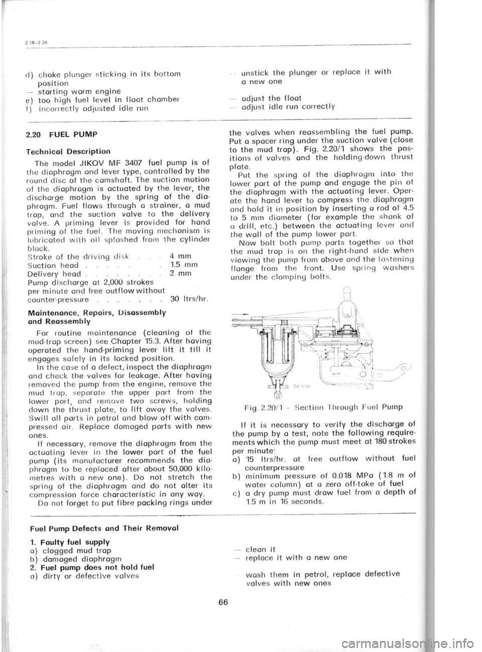
Put o spocer ring under the suction volve (close
to the mud trop). Fig.2.2Ol1 shows
the pos-
itions of volves ond the holding-down thrust
plote. Put the spring
of the diophrogm into
the
lower port
oi the pump
ond engoge the pin
ot
the diophrogm with the octuoting lever. Oper-
ote the hond lever
to compress the dioPhrogm
oncl hold it in position by inserting o
rod of 4.5
to 5 mm diorneter (for
exomple the
shonk of
o drill, etc.) between the octuoting lever
ond
the woll of the pump
lower
Port.
Now bolt both pump
ports
together so thot
the mud trop is on the
right-hond side when
viewing the pump from obove
ond the fostening
flonge from the front. Use spring
woshers
under the clomping bolts.
Fig.2.2011 -
Section Through
Fuel Pump
lf it is necessory to verify
the dischorge of
the pump
by o test, note the following require'
mentswhich the pump
must meet otl80strokes
per minute:
o) 15 ltrs/hr. ot f ree outf low without
fuel
counterpressure
b) minimum pressure
of 0.018 MPo (1.8
m of
woter column) ot
o zero off'toke of fuel
c) o dry pump
must drow fuel from o
depth of
1.5 m in 16 seconds.
Fuel Pump Defects ond Their Removol
1. Foulty fuel
supply
o) clogged mud trop
b) domoged diophrogm
2. Fuel pump
does not hold fuel
o) dirty or defective volves cleon it
reploce it
with o new one
wosh them in petrol,
reploce defective
volves with new ones
66
Page 146 of 238

11.4-11.5
I
I
I
F
r
t'
on to the coolont tonk.
Hose
clips ore formed
either by metol strips
or lengths
of wire. When
tightening the wire clips, toke core not to
domoge the rubber of the hoses.
To Fosten Pipes ond
Hoses
A correct winding of the strip is importont
to ensure o self-locking clomping of the strip
clips -
see Fig. 11.411.
Fig.11.Al1- Diogrom showing
the threoding
of
the clip strip through
the clip closp ond
the
direction of rototion of
the tightening cotter
pin -
the diogrom hos generol
opplicobility
1 -
Strip clip,2 -
Closp, 3 -
Cotter pin
The moin pipeline
routed under the cor f loor
consists of front ond reor pipes.
They ore em-
bedded in o chonnel moulded in the floor
boords ond rest on on insuloting (polysterene)
podding. From below, they ore protected
by
o guord,
the copscrews of which ore locked
in
position by spring woshers.
Use pipe
holders (yokes) to fosten the pipe-
line to the floor. In
the front
ond reor port
of
the cor, tighten
the pipes
over the insulotion
lrod ond insert
spring ond ploin
woshers under
the nuts.
Do not use insulotion pods
for bends
forming the tronsition from
the front
ond reor
lower flot ports.
Use spring woshers under
the
heods of copscrews.
Before instolling the pipes, prepore
ouxiliory
yokes (or use lengths of wires ottoched to the
provisionolly screwed-in copscrews of the pipe-
line guord) to liold the pipes
in the moulded
chonnel in
the floor before
the finol fostening
of their guord.
The woter line runs
under the cor together
with other lines, pull-rods,
etc. For their mutuol
ref otive orrongement see Chopter 12.7. Removol
To moke the underbody occessible for hond-
ling the pipes,
ploce
the cor over o floor pit
or
on o romp. The minimum required cleoronce is
obout 650 mnr.
1. Remo.re the guords
of the pipes
ond the
fuel tonk, lift owoy the spore wheel, ond loosen
the yokes
holding the pipes
to the floor.
2. Remove droin screws to droin the coolont
from the pipes -
see the illustrotion in Chop-
ter 15.'13.
3. Remove one hose clip in the middle
of the
cor to disconnect
the pipes
(ottention -
the
remoining coolont will f low out), ond dis-
ossemble the line.
4. Disconnect the pipe
ends from the hoses,
ond detoch the pipes
from the floor or other
ports of the cor.
5. Pull out the reor pipes
possing
them core-
fully oround the vorious cor ports.
6. Pull out the front pipes.
Turn
the front
wheels into their left lock position,
disconnect
the steering linkoge from the steering
reloy
lever ond the steering knuckle orm of the
right-
hond wheel, ond push
the linkoge ogoinst the
oxle body. While removing the pipes,
rotote the
left-hond pipe clockwise (when
viewing the cor
front end), ond the right-hond pipe
onticlock-
wise.
Reinstollotion Reverse the dismontling procedure
when re-
instolling the woter line. While connecting the
steering linkoge, poy
ottention to the condition
of boll pin
seoling cups (fit
new cups if the old
ore domoged). Fill in the recommended
coolont
ond bleed the cooling system.
11.5 COOLANT TEMPERATURE CONTROL
Throughf low Thermostot
This thermostot shuts off the inlet of the
coolont into the rodiotor
during the engine
heoting-up period. lt is mounted on the engine
- see Chopter 2.3, por.
30.
The thermostot operotes within the following
volues:
it begins to open ot 80+2"C
it is fully open ot 90+4oC
its lift ot full opening
11 mm
When closed, it
is permitted
to let poss
o nroximum
of 0.5 litres
of coolont per
minute,
ond it must not be closed by o bock pressure
of 0.16 MPo (1.6
kg/cm2).
When removing the thermostot by rototing
tlre rivet in the volve disk, breok owoy sedi-
I i
i 152
Page 156 of 238
12.6-12.f
2. Proceeding fronr below, rernove
the fuel
tonk sheet guord
ond the guord
of the cooling
woter pipes.
3. Disconnect the pipe
of the clutclr hydroulic
line from the clutch releose hose brocket.
4. Screw out droin plugs
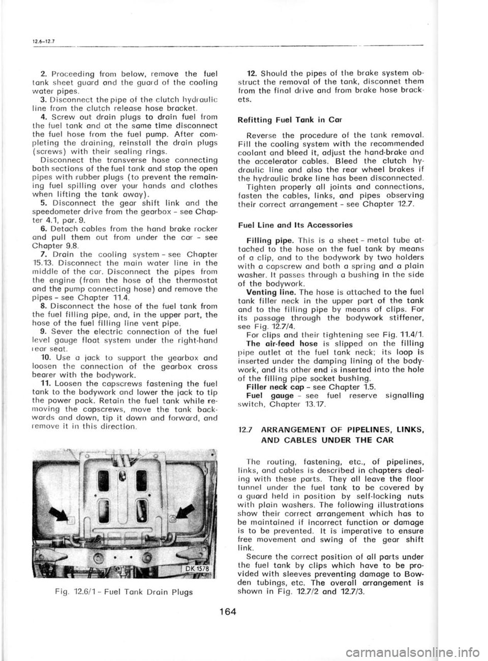
to droin fuel from
the fuel tonk ond ot the some time disconnect
the fuel hose from
the fuel pump.
After com-
pleting the droining, reinstoll the droin plugs
(screws) with their seoling rings.
Disconnect the tronsverse hose connecting
both sections of the fuel tonk ond stop the
open
pipes with rrubber
plugs (to prevent
the remoin-
ing fuel spilling over your
honds ond clothes
when lifting
the tonk owoy).
5. Disconnect the geor
shift link ond the
speedometer drive from the georbox -
see Chop-
ter 4.1, por.9.
6. Detoch cobles from the hond broke rocker
ond pull
them out from under the cor -
see
Chopter 9.8. 7. Droin the cooling system -
see Chopter
-15.13.
Disconnect the moin woter line in
the
rniddle of the cor. Disconnect the pipes
from
the engine (from
the hose of the thermostot
ond the pump
connecting hose) ond remove
the
pipes -
see Chopter 11.4.
8. Disconnect the hose of the fuel
tonk from
the fuel filling pipe, ond, in the upper port,
the
hose of the fuel filling line vent pipe.
9. Sever the electric connection of the fuel
level gouge
floot system under tlre right-hond
I eor seot.
10. Use o
iock to support
tl're georbox
ond
loosen tlre connection of the georbox
cross
beorer with the bodywork.
11. Loosen the copscrews fostening the fuel
tonk to the bodywork ond lower the
iock to tip
the power
pock.
Retoin the fuel tonk while ne-
nroving the copscrews, move the tonk bock-
words ond down, tip it down ond forword, ond
remove it in
this direction. 12. Should
the pipes
of the broke system ob-
struct tlre removol of the tonk, disconnet them
from the finol drive ond from broke hose brock-
ets.
Refitting Fuel Tqnk in Cor
Reverse the procedure
of the tonk removol.
Fill the cooling system with the recommended
coolont ond bleed it, odjust the hond-broke ond
the occelerotor cobles. Bleed the clutch hy-
droulic line
ond olso the reor wheel brokes if
the hydroulic broke line hos
been disconnected.
Tighten properly
oll joints
ond connections,
fosten the cobles, links, ond pipes
obsenving
their correct orrongement -
see Chapter 12.7.
Fuel Line ond lts Accessories
Filling pipe.
This is q
sheet -
metol tube ot-
toclred to
the hose on the fuel tonk by meons
of o clip, ond to
the bodywork by two holders
with o copscrew ond both o spring ond o ploin
wosher. lt posses
througlr o bushing in the side
of the bodywork. Venting line. The hose is ottoched to the fuel
tonk filler neck in the upper port
of the tonk
ond to the filling pipe
by meons
of clips. For
its possoge
through the bodywork stiffener,
see Fig. 12.714. For clips ond their tightening see
Fig. 11.4/1.
The oir-feed hose
is slipped on the filling
pipe outlet ot
the fuel tonk neck; its
loop is
inserted under the domping lining of the body-
work, ond its other end is inserted into the hole
of the filling pipe
socket bushing.
Filler neck cop -
see Chopter 1.5.
Fuel gouge -
see fuel reserve signolling
switch, Chopter 13.17.
12.7 ARRANGEMENT
OF PIPELINES, LINKS,
AND CABLES UNDER THE
CAR
The routing, fostening, etc., of pipelines,
links, ond cobles is described in
chopters deol-
ing with these ports.
They oll leove the floor
tunnel under tlre fuel tonk to
be covered by
o guold
held in position
by self-locking nuts
with ploin
woshers. The following
illustrotions
show their correct orrongement which hos to
be mointoined if incorrect function or domoge
is to be prevented.
lt is imperotive to ensure
free movement ond swing
of the geor
shift
link.
Secure the correct position
of oll ports
under
the fuel tonk by clips which hove
to be pro-
vided with sleeves preventing
domoge to Bow-
den tubings, etc. The overoll orrongement is
shown in
Fig. 12.712 ond 12.713.
Fig.
12.611- Fuel Tonk Droin
Plugs
164
Page 165 of 238
'i
iiiI 14. Fuse box
Centrol connection of conductors -
do not
seporote them from the bunch!
15. Direction indicotor switches, dip switch,
and horn switch
eight-pole terminol
boord
six-pole terminol boord
16. Porking light switch ond high beom feeder four-pole terminol boord
17. Switch box femole connectors 5.5 with symbols "15",
"30", ond '50"
to be
connected to symbols
"15u, "30', ond '50"
on the switch box
18. Instrument ponel
ten-pole terminol boord
six-pole terminol boord
eorthing coble with lug
'19. Heoter switch
four-pole terminol boord
20. Switch of disobility lights
six-pole terminol boord
21. Door switch, right-hond
green -
femole connector 5.5
22. Dome light,
right-hond
green -
femole connector 5.5
red -
femole connector 5.5
23. Stop switches
forked (yellow) -
femole connectors 5.5 .
red -
femole connector 5.5
white -
femole connector 5.5upper ond lower
switch
upper switch lower switch
24.Fuel gouge block -
femole connector 5.5
yellow -
femole connector 5.5
blue -
femole connector 5.5
to be connected to the respective pins
(blodes) of the some colour of the fuel gouge
25. Storter motor, reversing
lomp switch
conductors with lugs stater motor moin
terminol boord
storter motor
control switch
green -
femole connectors 5.5 heodlomp switch
26. Oil pressure
gouge,
thermometer, corburettor
iet seporotor
green -
femole connector 5.5 yellow
-
femole connector 5.5
green - telethermometer
primory element
femole connector 7.
corburettor
iet seporotor
27. lgnition coil, voltoge regulotor, olternotor,
tochometer
conductor with femole connector ond
bronching lug
femole connector-regulotor terminol 15/54
lug -
ignition coil terminol 15
blue -
femole connector 5.5,
symbol "R"
. regulotor terminol "R"
yellow -
femole connector 5.5,
symbol "M"
regulotor terminol "M"
blue -
connector "R"
. olternotor terminol "R"
yellow -
connector "M".
olternotor terminol "M"
lug terminol "+B"
conductor with
lug ignition coilterminol "1"
(tochometer operotion
)
28. Toil lomp cluster, right.hond
yellow -
femole connector 5.5 toil light
block -
femole connector 5.5 direction indicotors
red -
femole connector 5.5 stop light
green -
femole connector 5.5 reversing lomp
29. Licence plote light
conductors with femole connectors 5.5
30. Toil lomp cluster, left.hond
se point
28.
b) Connection
of free conductors
1. Storoge bottery
bottery coble positive
(*)
terminol -
storter motor
bottery eorthing strip negotive (-)
terminal -
bodywork (eorthing conductor)
2. Engine engine eorthing strip (fostening
lug) -
engine cross beorer (eorthing conductor)
3. Distributor speciol coble from distributor to
ignition
coil; end with interference suppressing
terminol to distributor
coble from distributor to ignition coil
terminol "1"
cylindricol
(pin)
connector
pressure gouge172
Page 203 of 238

l4.l
l-14.12
has two anchoring points.
The seat belts have
anchoring bolts
on the size 7/16-20 UNF-2A'
In f ront, the anchoring threads
are easily
accessible being provided
on the door posts
(remove only one of the pair
of pins
covering the
thread), on sills
below the posts,
and on
the sides
of the'floor tunnel
behind the front seats'
Anchoring points
for rear seat belts are shown
in the illustation. For the seat
belt of the person
sitting in the
middle, the threads are under the
seat cushions and rather removed from each other
(A3). For the seat belts of persons
occupying the
butside places
the threads are also under the
cushions, nearer to the centre (A2),
in the body
sides close to the cusions (82),
and in window
pillars (C2). These latter threads can be found by
touch in the point
of intersection of the plane
passing about 165 mm
above the
rear window
parcel tray and in parallel
with the door frame at a
distance of about 85 mm. To gain
access to
them,
it is necessary to cut through the trimming.
We must stress that for the fitting of points A2
and A3, the bolts should not protrude
beyond the Fig.M.11l2
-
Lower Anchoring Points
14-12 FACIA
l-he focio cctl be rentoved otter unsct-ewlllg
the nuts of its peripherol bolts ond
ofter lifting
owoy the instrument ponel -
see Chopter '13'15'
It is olso necessory to
remove the steering
wheel with the shroud of
the steering wheel
shoft (see
Chopters 7.7
ond
7.8), ond the heoter
control ponel
(see ChoPter 11.0).
The bolts holding down the focio
ore occess-
ible ofter removin! the
instrument ponel
ond
the heoter control ponel, ond
ofter swinging. out
the glove
box. To swing
out the glove
box,
open its lid ond loosen tlre screws of its
stops'
Fig. 14.1111 -
Upper Anchoring Point
captive not more
than 1lz mm or there is every
likelihood of damaging the
fuel tank.
The depth of the nut from the mounting face
is
15 mm.
Child seat fixing
Follow the seat belt manufacturers instructions
as to the spacing of the belt straps.
The straps can be mounted to the rear parcel
shelf if the mounting holes are drilled 30 mm from
the front engine bulkhead. The
sound deadening
trim in the engine compartment
will need to be
lowered to fit the spreading plate
and nut.
Be careful when drilling the shelf, not to
scratch the rear screen. Fig.
14.1211 -
Focio Mounting Points
14.13 WATER LEAKS
To determine the
source of
a water leak
proceed in a progressive
manner.
1. Determine area
water finally rests'
2. lf possible follow
water trace to
source'
3. lf hot, remove carpets and clutter'
4. Dry car inside
and out'
5. Us'e a sprinkler rather
than
a hose jet'
6. Start on the
underside of
the vehicle and
work up. Do not
do any adjustments or
sealing until after the
first test.
7. When"you have
finished adjustments and
sealing RE
TEST.
212
Page 214 of 238

Fig.
15.3/8 -
Distributor Adiusting Elements
1 -
contoct holder, 2 -
rotor orm, 3- com,
4 -
distributor brocket, 5 -
distributor brocket
clomping bolt
Alwoys turn the engine clockwise to eliminote ony ploy
in the distributor drive geor
ond to
ovoid loosening of the bolt. To relieve the
com-
pression resistonce, it
is recommended to bock
off the sporking plugs.
b) Stroboscopic method:
When using this method, the volues of the
bosic ignition timing ond
the odvonce con-
trolled by the centrifugol timing control (for
its
diogrom refer to Chopter 13.5) should be odded
upwhile multiplying bytwo
the odded upvolues
occording to the diogrom. Any effect of the
vocuum control must be
eliminoted by discorr-
necting the respective hose (connecting
the
distributor vocuum unit with the corburettor).
The meosuring procedure
is indicoted by the
diognostic equipment itself.
To Adiust ldling Speed
Use the oir-correction screw (speed
cor-
rection screw). The speed decreoses when ro-
toting the screw clockwise ond increoses when
rototing it onticlockwise.
Adiust the idling speed in occordonce with
the tochometer ond within the limits specified
in the following porogroph "To
Adiust ldle
Run". The engine must be wormed-up
before
storting the odjusting procedure (see
olso the
following porogrophs) ond its ignition must be
in perfect
condition (distributor
contoct-breoker
points, sporking plug
electrodes, ond ignition
odvonce).
N o t e : For the bosic position
of the odiusting
screw refer to Chopter 2.19 - "Mointenonce
ond
Adiusting". Fig.
15.3/9 -
Air-correction Screw -
idling speed
correction screw
To Adiust ldle
Run
Acljust the contoct-breoker point
gop,
the gop
of the sporking plug
electrodes, ond
the ig-
nition odvonce. Then check
the
volve cleoronce
(if there is no cleoronce, odiust
the
volves),
cleon the oir intoke filter
element, ond moke
sure thot the occelerotor pedol link hos
the re'
quired free trovel -
see Chopter 12.2-
Use o needle to remove the plug
covering
the fost-idling screw
ond let the engine run ot
obout 2,000 r. p.
m. to ottoin on oil temperoture
of 70oC. Insert the probe
of the thermonreter
into the hole for the oil diPstick'
Now connect the
speed indicotor (tocho-
meter) ond the onolyzer of
corbon
.monoxide
(contoined in exhoust fumes). Use
the oir'cor-
iection screw (Fig.
15.3/9) to set the
speed
-r-?n
at 800 l;; t.
p. ni. cnd the fost-idling screw
(Fiq. 15.3/10) to odiust the
content of corbon
moioxide to 2*0.50/s or the oir-fuel proportion-
by-weight mixing rotio,
comporoble with
the
specif ied corbon monoxide content, to
1+.2 +$.t.
After about one minute of
the continued idle
running recheck the odiustment ond
correct it,
if necelsory. Close the hole
with the
fost-idling
screw by driving in o
new plug with
its bottom
outword.
Note: For the bosic position of
odiusting
screws refer to Chopter 2.19 - "Mointenonce
ond Adjustment".
To Lubricote Accelerotor Mechonism
Pour severol drops of oil into
the end of the
bowden coble tubing ond lubricote both
ioints
(on top ond below)- of the corburettor pull-rod
itself with obout one drop of oil. Then
depress
224