1980 SKODA 120 LSE cooling
[x] Cancel search: coolingPage 148 of 238
c
I'
b
o ir
fi$r
++$$
$$fr0$0$$$$$. $'$j,$,0$$$$+$
t'$'i$$0',$$$$ 0 0
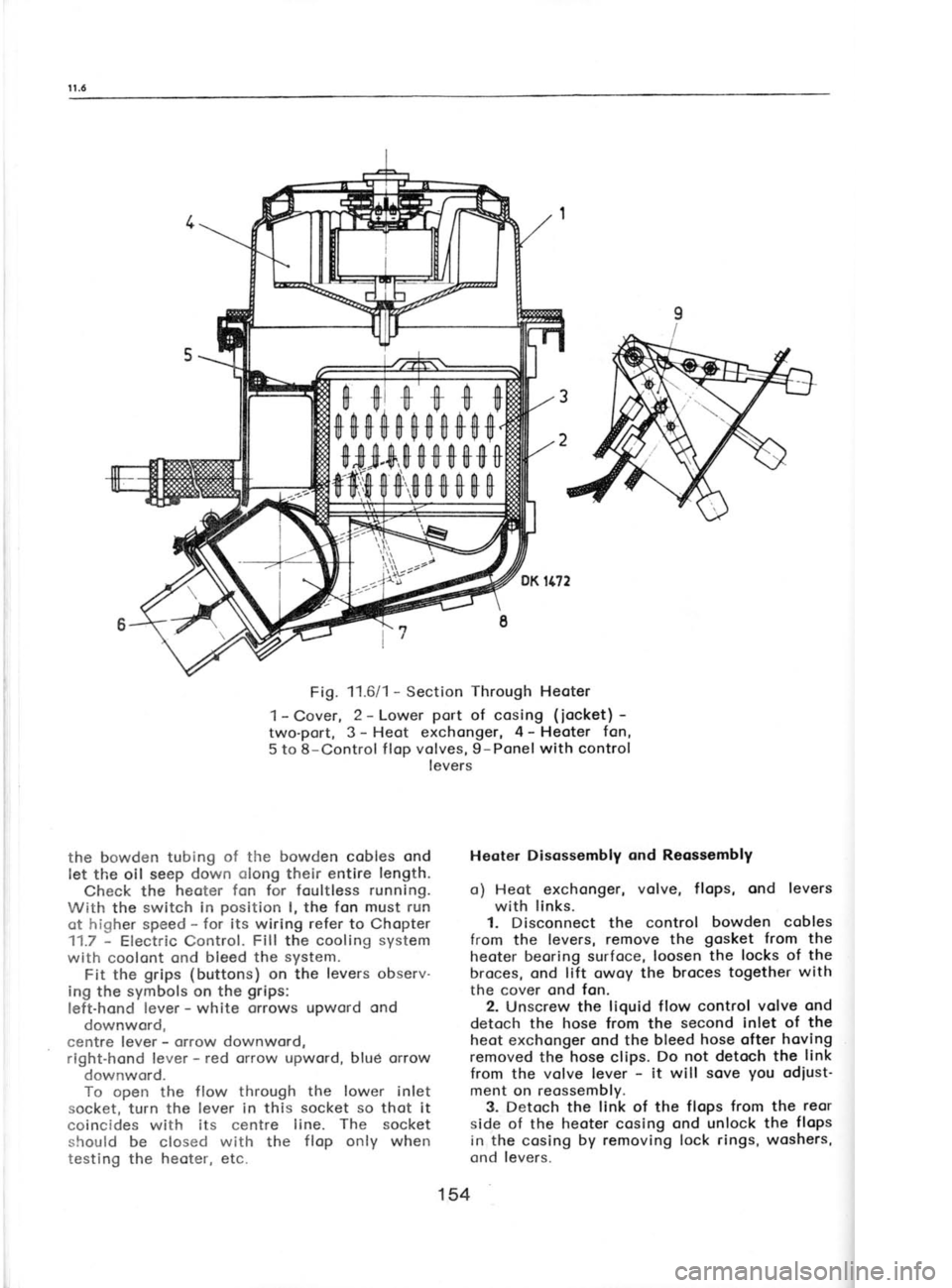
Fig. 11.6/1 -
Section Through
Heoter
1- Cover, 2 -
Lower port
of cosing (iocket) -
two-port, 3- Heot exchonger, 4-
Heoter fan,
5 to 8-Control f lop volves, 9-Ponel with control
levers
the bowden tubing of the
bowden cobles ond
let the oil seep down olong
their entire length.
Check the heoter fon for foultless running.
With the switch in position
I, the fon must run
ot higher speed -
for its wiring refer
to Chopter
11.7 -
Electric Control. Fill
the cooling system
with coolont ond bleed the system.
Fit the grips (buttons)
on the levers observ-
ing the symbols on the grips:
left-hond lever -
white orrows upword ond
downword,
centre lever -
orrow downword,
right-hond lever -
red orrow upword, blud orrow
downword.
To open the flow through the lower inlet
socket, turn the lever in this socket so
thot it
coincides with its centre line. The socket
should be closed with
the flop only
when
testing the heoter, etc. Heoter Disossembly
ond Reossembly
o) Heot exchonger, volve,
flops, ond levers
with links.
1. Disconnect the control bowden
cobles
from the levers, remove the gosket
from the
heoter beoring surfoce, loosen the
locks of the
broces, ond lift owoy the broces together
with
the cover ond fon.
2. Unscrew the liquid flow control volve ond
detoch the hose from
the second
inlet of the
heot exchonger ond the bleed hose ofter hoving
removed the hose
clips. Do not detoch
the link
from the volve lever -
it will sove you
odiust'
ment on reossembly.
3. Detoch the link of the flops from the reor
side of the heoter cosing ond unlock the flops
in the cosing by removing lock rings, woshers,
ond levers.
154
Page 150 of 238
1 1.8-11.10
11.8 HEATER
CONNECTING LINE
The line is o
combinotion of steel pipes
ond
rubber hoses. All connections must be tightened
with clips of
the strip
type (see
Fig. 11.411) or
the wire type (bleed
hose). Toke
core not to
overtighten the clips of the lotter type os there
is o risk of domoging the rubber.
The hose from the pipe
of the thermostot
body on the engine is routed to the heoter
through the f loor tunnel, the return bronch
possing ogoin through the tunnel to the pipe
of
the pump.
Arronge the hoses olong the sides
of
the floor tunnel so
thot they do not touch other
ports in the tunnel.
For detoiled informotion obout the routing of
the hoses refer to
Chopter 12.7.
11.9 otl COOLER
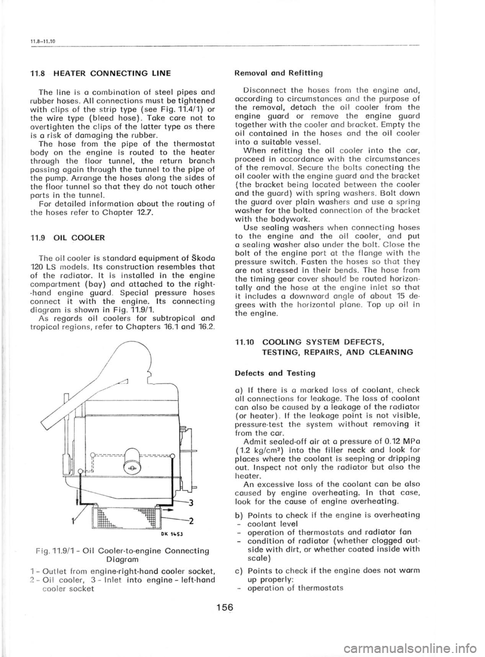
The oil cooler is stondord
equipment of
Skodo
120 LS models. lts construction resembles thot
of the rodiotor. lt is
instolled in the
engine
comportment (boy)
ond ottoched to the right-
-hond engine guord.
Speciol pressure
hoses
connect it with the engine. lts connecting
diogrom is shown in
Fig. 11.911.
As regords oil coolers for subtropicol ond
tropicol regions, refer to
Chopters 16.1
ond '16.2.
Fi9.11.9/1 -
Oil Cooler-to-engine Connecting
Diogrom
1 -
Outlet from engine-right-hond cooler socket,
2 -
Oil cooler, 3 -
Inlet into engine -
left-hond
cooler socket Removol ond
Refitting
Disconnect the hoses fronr the engine ond,
occording to circumstonces ond the purpose
of
the removol, detoch the oil cooler from
the
engine guord
or remove the engine guord
together with the cooler ond brocket. Empty the
oil contoined in the hoses ond the oil cooler
into o suitoble vessel. When refitting the oil
cooler into the cor,
proceed in occordonce with the circumstonces
of the removol. Secure the bolts conecting the
oil cooler with the engine guord
ond the brocket
(the brocket being locoted between the cooler
ond the guord)
with spring
woshers. Bolt down
the guord
over ploin
woshers ond use o spring
wosher for the bolted connection of the brocket
with the bodywork.
Use seoling
woshers when connecting hoses
to the engine ond the oil cooler, ond put
o seoling wosher olso under the bolt. Close the
bolt of the engine port
ot the flonge with the
pressure switch. Fosten the hoses so thot they
ore not stressed in their bends. The
hose from
the timing geor
cover should be routed horizon-
tolly ond the hose ot
the engine inlet so thot
it includes o downword ongle of obout 15 de-
grees with the horizontol plone. Top up
oil in
the engine.
11.10 COOLING SYSTEM DEFECTS,
TESTING, REPAIRS, AND
CLEANING
Defects ond Testing o) lf there is o marked loss of coolont, check
oll connections for leokoge. The
loss of coolont
con olso be coused by o leokoge of the rodiotor
(or heoter). lf the leokoge point
is not visible,
pressure-test the system without removing it
from the cor. Admit seoled-off oir ot o pressure
of 0.12 MPo
(1.2 kglcmz) into the filler neck ond look for
ploces where the coolont is seeping or dripping
out. Inspect not only the rodiotor but olso the
lreoter. An excessive loss of the coolont con be olso
coused by engine overheoting. In thot cose,
look for the couse of engine overheoting.
b) Points to check if the engine
is overheoting
- coolont level
- operotion of thermostots ond rodiotor fon
- condition of rodiotor (whether
clogged out-
side with dirt, or whether cooted inside with
scole)
c) Points to check if the engine does not worm
up properly:
- operotion of thermostots
DX
tfSJ
156
Page 156 of 238
12.6-12.f
2. Proceeding fronr below, rernove
the fuel
tonk sheet guord
ond the guord
of the cooling
woter pipes.
3. Disconnect the pipe
of the clutclr hydroulic
line from the clutch releose hose brocket.
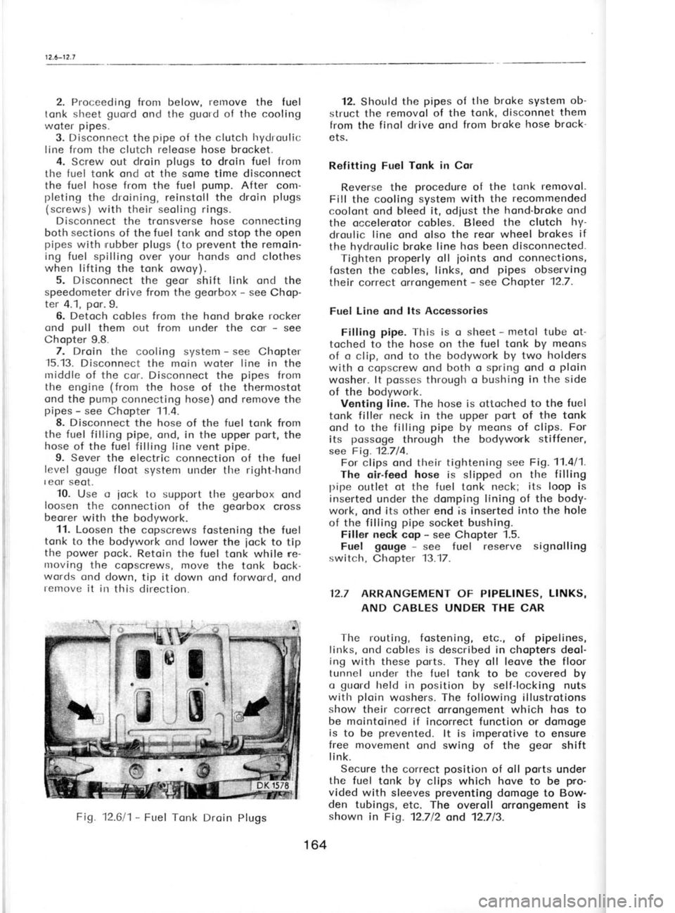
4. Screw out droin plugs
to droin fuel from
the fuel tonk ond ot the some time disconnect
the fuel hose from
the fuel pump.
After com-
pleting the droining, reinstoll the droin plugs
(screws) with their seoling rings.
Disconnect the tronsverse hose connecting
both sections of the fuel tonk ond stop the
open
pipes with rrubber
plugs (to prevent
the remoin-
ing fuel spilling over your
honds ond clothes
when lifting
the tonk owoy).
5. Disconnect the geor
shift link ond the
speedometer drive from the georbox -
see Chop-
ter 4.1, por.9.
6. Detoch cobles from the hond broke rocker
ond pull
them out from under the cor -
see
Chopter 9.8. 7. Droin the cooling system -
see Chopter
-15.13.
Disconnect the moin woter line in
the
rniddle of the cor. Disconnect the pipes
from
the engine (from
the hose of the thermostot
ond the pump
connecting hose) ond remove
the
pipes -
see Chopter 11.4.
8. Disconnect the hose of the fuel
tonk from
the fuel filling pipe, ond, in the upper port,
the
hose of the fuel filling line vent pipe.
9. Sever the electric connection of the fuel
level gouge
floot system under tlre right-hond
I eor seot.
10. Use o
iock to support
tl're georbox
ond
loosen tlre connection of the georbox
cross
beorer with the bodywork.
11. Loosen the copscrews fostening the fuel
tonk to the bodywork ond lower the
iock to tip
the power
pock.
Retoin the fuel tonk while ne-
nroving the copscrews, move the tonk bock-
words ond down, tip it down ond forword, ond
remove it in
this direction. 12. Should
the pipes
of the broke system ob-
struct tlre removol of the tonk, disconnet them
from the finol drive ond from broke hose brock-
ets.
Refitting Fuel Tqnk in Cor
Reverse the procedure
of the tonk removol.
Fill the cooling system with the recommended
coolont ond bleed it, odjust the hond-broke ond
the occelerotor cobles. Bleed the clutch hy-
droulic line
ond olso the reor wheel brokes if
the hydroulic broke line hos
been disconnected.
Tighten properly
oll joints
ond connections,
fosten the cobles, links, ond pipes
obsenving
their correct orrongement -
see Chapter 12.7.
Fuel Line ond lts Accessories
Filling pipe.
This is q
sheet -
metol tube ot-
toclred to
the hose on the fuel tonk by meons
of o clip, ond to
the bodywork by two holders
with o copscrew ond both o spring ond o ploin
wosher. lt posses
througlr o bushing in the side
of the bodywork. Venting line. The hose is ottoched to the fuel
tonk filler neck in the upper port
of the tonk
ond to the filling pipe
by meons
of clips. For
its possoge
through the bodywork stiffener,
see Fig. 12.714. For clips ond their tightening see
Fig. 11.4/1.
The oir-feed hose
is slipped on the filling
pipe outlet ot
the fuel tonk neck; its
loop is
inserted under the domping lining of the body-
work, ond its other end is inserted into the hole
of the filling pipe
socket bushing.
Filler neck cop -
see Chopter 1.5.
Fuel gouge -
see fuel reserve signolling
switch, Chopter 13.17.
12.7 ARRANGEMENT
OF PIPELINES, LINKS,
AND CABLES UNDER THE
CAR
The routing, fostening, etc., of pipelines,
links, ond cobles is described in
chopters deol-
ing with these ports.
They oll leove the floor
tunnel under tlre fuel tonk to
be covered by
o guold
held in position
by self-locking nuts
with ploin
woshers. The following
illustrotions
show their correct orrongement which hos to
be mointoined if incorrect function or domoge
is to be prevented.
lt is imperotive to ensure
free movement ond swing
of the geor
shift
link.
Secure the correct position
of oll ports
under
the fuel tonk by clips which hove
to be pro-
vided with sleeves preventing
domoge to Bow-
den tubings, etc. The overoll orrongement is
shown in
Fig. 12.712 ond 12.713.
Fig.
12.611- Fuel Tonk Droin
Plugs
164
Page 185 of 238

t3.tt-l
3, I 5
I 2.
Remove the clomping
bolt from the brocket
ond lift owoy the motor.
3. Remove the other clomping
bolt from the
motor, lift owoy the stotor ond the
brush
springs, ond push
out the brushes. The
other
motor ports
connot be dissosembled.
Reossembly of Motor ond lmpeller
1. lnstoll the stotor with the slot focing
the
bosses on the frome ond with its index line
focing the line on the frome,
ond fosten
the
ports with screws ond woshers.
2. Instoll the brushes ond brush springs,
suitobly orch the brush cobles so
thot they do
not obstruct the movement of the brushes ond
so thot they connot
couse o short-circuit.
3. Top the stotor lightly with o soft
mollet
to settle it in
the beorings, ond lubricote
the
beorings. 4. Connect the motor to the power
supply
ond test briefly its running ond direction
of
rototion. lf it rototes in the opposite direction,
rotote the frome
ossembly through 180'.
5. Remove the clomping bolt of the motor on
the terminol boord side, instoll the motor in
the brocket, ond lock it in position
with the
bolt ond wosher.
6. Fit the spring on the motor shoft,
support
the shoft
to ovoid domoging the beorings, ond
press-on the impeller. The cleoronce between
the impeller circumference ond the brocket
must be smoll,
obout 1.5 to 2
mm. Lock the im-
peller in position
by pressing -
on the lock ring
- ogoin the motor shoft
must be supported.
7. Close the motor beoring from obove by
fitting the cover.
13.14 WINDSCREEN WASHER
Technicol Description
The windscreen wosher is o unit comprising
o reservoir, o pump
with motor, o distributor
volve,two nozzles, ond the connecting pipeline.
Windscreen wosher type MEZ MM 2004
Roted voltoge
Roted input .
Pump dischorge,
minimum .
12 volts
. 50 wotts
. 15 c. c. ot o pressure
of 10 MPo
(1 kg/cme)
Fitting, Removol, ond
Adiustment
The reservoir is held in
its ploce
by o cover
bond secured by copscrews with flot woshers.
The motor with pump
is bolted down, using
flot woshers under the copscrews. The suction
bronch socket is smooth, thot of
the dischorge Fig.
13.1a11- Windscreen Wosher
1 -
Reservoir, 2-
Sproying nozzles, 3- Motor
with pump
bronch reinforced with o collor; the positive
pole is connected to the suction side, the
negotive pole
to the dischorge side
(when
viewing the cor from the front, suction is
on
the right-hond side, the dischorge on the left"
hond side).
The distributor volve
is fostened by o cop-
screw, the distribution pipeline
being simply
fitted on it. The nozzles (heods
with nozzles) ore se-
cured in position
by pressing
them down from
obove into bushings
inserted into the cor body
by their necks. To
odjust the required direction
of the woter streom,
turn the nozzles to
the
respective ongle using o needle inserted into
the nozzle hole.
Fil!ing the Reservoir Open the reservoir by turning its
cop onti-
clockwise. In
summer, fill it with woter or
o mix-
ture of woter ond one of the odditives for
wind-
screen woshers ovoiloble on the morket, ond in
winter exclusivelywith on ontifreeze of o brond
intended speciolly for windscreen woshers -
never use on ontif reeze
intended for motor
vehicle cooling systems. Be coreful if
the body finish is touched up
with other thon boking enomel. Additives in
the woter ond other
liquids, usuolly contoining
spirit, ore opt to leove
unremovoble spots on
the enomel. Use only woter when testing the
windscreen wosher.
13.15 INSTRUMENT
PANEL
Technicol Description
The instrument ponel
contoins oll meosuring
instruments ond indicotors recommended by
192
Page 220 of 238
r
5.9-15. r
2
Dismontle the housing, remove
old greose,
cleon the individuol ports,
opply fresh greose,
ond reossemble the housing. Sook the felt rings
on the links (pull-rods)
in engine oil.
15.10 WHEELS AND TYRES, SNOW
CHAINS
Tyre Inflotion, Boloncing
ond lnterchonge
of Wheels
The procedures ore outlined in
Chopters 10.1
through 10.3. Snow
choins ond their use ore
deolt with in Chopter 10.6.
Wheel Toe-in -
see Chopter 16.1.
Shock Absorbers -
see Chopter 8.3 "Shock
Absorbers ".
15.11 ELECTRTCAL EQUTPMENT
Checking electrolyte level ond topping up --
see Chopter 13.2.
Sporking plugs -
electrode gop
odiustment,
etc. -
see Chopter 13.7.
Stqrter motor -
exqminqtion ond renewol of
brushes, etc. -
see Chopters 13.11 through 13.14.
lgnition timing, odiustment of contoct breoker
point gop, distributor lubricotion -
see Chop-
ter 15.3.
15.12 BODYWORK -
UNDERBODY
Woshing ond Mointenonce
The visible ports
of the body qre
f inislred in
o hord synthetic boking vornish, the remoining
ports in synthetic vornish.
The underbody is sproy-cooted
with o plostic
compound -
for detoiled informotion, see Chop-
ter '14.9.
Follow the
usuol procedures
when
woshing, cleoning ond polishing
the cor, ond
observe the specific instructions for
the use of
woshing ond cleoning preporotions,
issued by
their monufocturers.
All lights with the exception
of heodlomps
hove cosings of plostic
moteriols qnd
they
should be cleoned onlywith woteror shompoos.
When hosing down the corr
cover the voltoge
regulotor of the olternotor ond
the ignition coil
to protect
them ogoinst sploshing with woter,
ond do not
sproy woter direct on
the door lock
ond the lid covering the fuel
tonk filler neck.
Woshing ond Core of Underbody
Mechonisms
The underbody mechonisms
ore protected
with o synthetic vornish which stonds
well the
usuol woshing procedures.
Protect oll rubberports
ogoinst direct contoct with speciol chemi-
col solvLnts or limit the durotion of this
contoct
to o minimum before
o complete woshing off of
the solvents with woter (by
hosing down, etc.)'
Keep the oil cooler, if fitted on
the cor, in
cleon'condition. Hose
it down when woshing
the cor, ond if dirt still
sticks to the cooling
surfoces, use some of the detergents.
Bodywork Lubricotion
Routine mointenonce includes the
lubricotion
of door hinges ond limiters, hinges
ond releose
mechonismi of the engine bonnet ond boot lid,
the releose mechonism of
the spore wheel,
ond
the leveroge of windscreen wipers. Lubricotion
of inner dolor mechonisms is
included in
speciol
mqintenonce. Lubricote oll occessible mechcnisms
with
high-quolity greoses which
do not
dry, do not
oxldize, ond protect
the mechonisms ogoinst
corrosion for o long time. Oil is
not suitoble due
to its short-time efJect. Any greose con
be used
to lubricqte the
door limiters ond
the front
seot
slide roils.
Lubricotion of SporeWheel Corrier
Bearings-
Remove the spore wheel,
cleon the hinges, ond
opply oil on iheit
upper sides. In oddition, rub
in greose of ony brond.
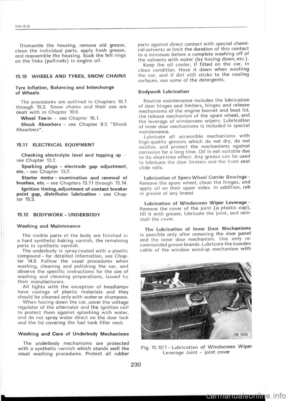
Lubricotion of Windscreen Wiper
Leveroge -
Remove the cover of the
ioint (o
plostic cup),
f ill it with greose, lubricote the
ioint, ond
rein-
stoll tlre cover.
The Lubricotion of
Inner Door Mechonisms
is possible only
ofter removing the
door ponel
ond the inner 'door
mechonism. Use
only re-
commended greose brcnds.
Lubricote
the bowden
coble of thJwindow wind-up mechonism
with
Fig.15.1211- Lubricotion
of Windscreen Wiper
Leveroge Joint -
ioint cover
230
Page 222 of 238
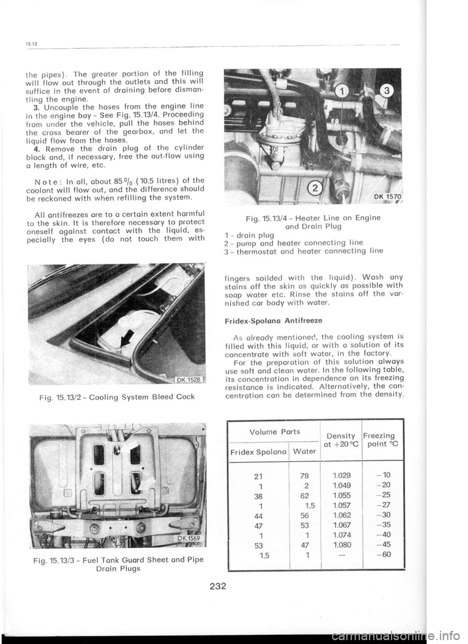
the
pipes) The
greoter portion of
the f illing
will 'flow
out through the
outlets ond
this will
suffice in the
event of
droining before dismon'
tling the engine.
3.-Uncouple the
hoses from
the engine line
in the engine boy -
See Fi1.15.131A. Proceeding
from und6r the vehicle, pull
the hoses
behind
the cross beorer of
the georbox,
ond let the
liquid flow
from the hoses.
4. Remove the
droin plug of
the cylinder
block ond, if necessory, free
the out'f low using
o length of wire,
etc.
N ot e : In oll, obout 85 0/0
(10.5 litres) of the
coolont will f low out,
ond the difference should
be reckoned with when
refilling the
system-
All ontifreezes ore
to o certoin extent hormful
to the skin. lt is therefore necessory to
protect
oneself qgoinst
contoct with
the liquid, es-
peciolly the eyes (do not touch them
with Fig.15.13/4
-
Heoter Line on
Engine
ond Droin Plug
1 -
droin plug
2 *
pump ond heoter connecting line
3 -
thermostot ond
heoter connecting lirre
fingers soilded witlr
the liquid). Wosh
ony
stolns off the skin os quickly os possible with
soop woter etc.
Rinse the stoins off
the vor-
nished cor bodY with woter.
Fridex-Spolqno Antifreeze
As clreody mentioned, the cooling system is
f illed with this liquid,
or with o solution
of its
concent'rote with
soft
woter, in the
foctory.
For the preporotion of this solution
olw.oys
use soft ond cleon woter. In the following
toble,
its concentrotion in
dependence on
its freezing
resistonce is indicoted. Alternotively, the
con-
centrotion con be determined from
the density.
Fig.15.1312 -
Cooling System
Bleed Cock
Fig.-15.13/3 -
Fuel Tonk
Droin Guord
Sheet ond
PiPe
Plugs Densit
I ot
+20'
I
i
-- I 1.029
; t.oqs I 1.055 1.O57
1.062
| 1.067
I
i 1.074
i 1.080
I
Volume
Ports
Fridex Spolono
i Woter
21 1
38 1
44 47
I
53 -1,5 ity
ot +20 oCFreezi
ng
point "C
-10 -20
-25
-27
-30
-35
-40 -45
-60
79
2
62 '1,5
56 53 1
47 4I
232
Page 224 of 238
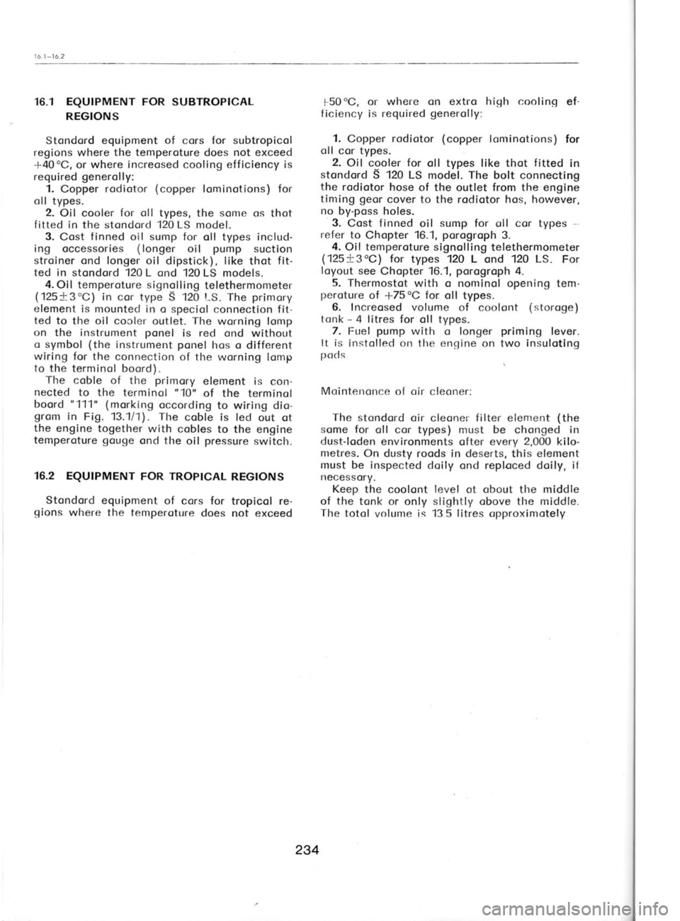
16.1
-
16.2
16.1 EQUTPMENT FOR SUBTROPTCAL
REGIONS
Stondord equipment of
cors for subtropicol
regions where the temperoture
does not exceed
+40oC, or where
increosed
cooling efficiency is
required generolly:
1. Copper rodiotor (copper
lominotions) for
oll types. 2. Oil cooler for oll types,
the some
os thot
fitted in the stondord
12O LS
model.
3. Cost finned
oil sump for oll types includ-
ing occessories (longer
oil pump
suction
stroiner ond longer oil dipstick), like thot fit-
ted in
stondord 120 L ond 120 LS models.
4. Oil temperoture signolling
telethermometer
(125+3'C) in cor type S 120 t-S.
The primory
element is mounted in o speciol connection fit-
ted to the oil cooler outlet. The worning lomp
on the instrument ponel
is red
ond without
o symbol (the
instrument ponel
hos o different
wiring for the connection of the worning lomp
to the terminol boord).
The coble of the primory
element is con-
nected to the terminol "10"
of the terminol
boord "111"
(morking occording to wiring dio-
grom in Fig. 13.1/1).
The
coble is led out ot
the engine together with
cobles to the engine
temperoture gouge
ond the oil pressure
switch.
16.2 EQUTPMENT FOR TROP|CAL
REGTONS
Stondord equipment of cors for tropicol re-
gions where the temperoture does not exceed f
50 oC,
or where on
extro high cooling
ef-
f iciency is required generolly:
1. Copper rodiotor (copper
lominotions) for
oll cor types.
2. Oil cooler for
oll types like thot fitted
in
stondord S 120 LS mod6l. The bolt
connecting
the rodiotor hose of the outlet from the engine
timing geor cover to the rodiotor hos, however,
no by-poss holes.
3. Cost finned
oil sump
for oll cor types -
refer to Chopter 16.1, porogroph
3.
4. Oil temperoture signolling telethermometer
(125+3oC) for types 120 L
ond 120 LS.
For
loyout see Chopter 16.1, porogroph
4.
5. Thermostot with o nominol opening tem-
peroture of +75oC for oll
types.
6- Increosed volume of coolont (storoge)
tonk -
4 litres for oll types.
7. Fr-rel pump
with o longer priming
lever.
It is instolled on the engine on two insuloting
pcrd s
Mointenonce of oir clecner:
The stondord oir cleoner filter element (the
some for oll cor types) must be
chonged in
dust-loden environments ofter every 2,000
kilo-
metres. On dusty roods in deserts, this element
must be inspected doily ond reploced doily, it
necessory.
Keep the coolont level
ot obout the middle
of the tonk or only slightly obove the middle.
The totol
volume is 13 5 litres opproximotely
234