Page 139 of 394
Downloaded from www.Manualslib.com manuals search engine 7. Water temperature sensor : ( DIAGRAM 7 )
- Disconnecting ‘the water temperature sensor should cause the engine to stall. when hot.
- Disconnect the E.C U
Using the ohmmeter, test the continuity of the circuit. and measure directly the resisitance using the sensor
cc - 10’ C )) R = 7 to 12 kR
cc + 20” C )t R = 2 to 3 kQ
cc t 80” C H R -. 250 to 400 Q
e
2
ii 8. Air temperature sensor : ( DIAGRAM 8 )
E
-E
?
U-J
- Disconnect the E.C.U. -
Using an ohmmeter, test the continuity of the circuit. and measure the resistance of the sensor between
terminals (( 6 )) and (( 27 ))
(c-10’ CH. R-8toIlkQ
N t 20” C 1) R = 2 to 3 kQ
tt + 50” C n R x 750 to 900 !J
Page 140 of 394

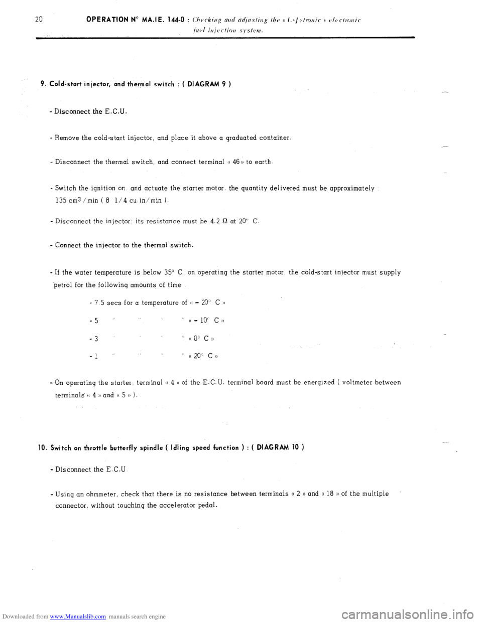
Downloaded from www.Manualslib.com manuals search engine 9. Cold-start injector, and thermal switch : ( DIAGRAM 9 )
- Disconnect the E.C.U.
- Remove the cold-start injector, and place it above a graduated container.
- Disconnect the thermal switch, and connect terminal (( 46 )) to earth
- Switch the ignition on and actuate the starter motor. the quantity delivered must be approximately
135 cm3 /min ( 8 l/4 cuin’min 1.
- Disconnect the injector: its resistance must be 4.2 Q at 20” C
- Connect the injector to the thermal switch.
- If the water temperature is below 35” C, on operating the starter motor, the cold-start injector must supply
petrol for the followinq amounts of time
- 7.5 sets for a temperature of (( - 20” C ))
-5 ” ” (( - 10“ c N
-3
” cc 0: c ))
-1 ” ” (( 20” c >)
- On operating the starter. terminal (( 4 )) of the E.C.U. terminal board must be enerqized ( voltmeter between
terminals (( 4 )) and 0 5 )) 1.
10. Switch on throttle butterfly spindle ( Idling speed function ) : ( DIAGRAM 10 )
- Disconnect the E.C.U
- Using an ohmmeter, check that there is no resistance between terminals N 2 H and (( 18 H of the multiple
connector, without touching the accelerator pedal.
Page 143 of 394
Downloaded from www.Manualslib.com manuals search engine 11. Switch on throttle butterfly spindle ( maximum power function ) ( DIAGRAM 11 )
- Disconnect the E.C.U.
- Using a battery operated ohmmeter, check there is no resistance between terminals (( 3 H and (( 18 )) of the
multiple connector board, with the accelerator pedal fully depressed
t 12. E.C.U. : ( DIAGRAM 12) +
s
*
i :
2 - Visually check the condition of the terminals ( male connectors on the E-C U., and female connectors
on the multiple connector socket ).
- With the engine running, tap lightly on the E.C.U., to detect any possible defect in the soldering ( dry
joints ).
Page 338 of 394

Downloaded from www.Manualslib.com manuals search engine Op. MA. 510-00 b 19 ELECTRONIC FUEL INJECTION ( i/ 1077 -)
TABLE OF FUSES ( LHD )
SUPPlY Fuses
Circuits protected
Ratinq Colour
Lightinq for qlove-box, bonnet and boot
Centre and rear interior lamps
Accessory terminal
Front L.H. mirror
16 Amps Green (F-2)
Flasher unit. and handbrake warninq lam1
Anti-theft
E Water temperature gauge
switch Cigar lighter
Reversinq lamps
Heated rear window, and warning lamp
+ )) Battery terminal
Instrument panel fuel gauge and low fuel
warninq lamp
Anti-theft
switch Liqhtinq for speed0 and tacho ( Rheostat )
16 Amps
(RFe3d)
_ Battery meter (thermal voltmeter ).
tachometer, warning lamp for brake pad
wear, coolant and engine oil temp. 1
enqine oil and hydr. fluid pressure.
direction indicators ( flashing )
Direction indicators
Voltage requlator
Windscreen wiper and washers
Horn
Windinq for relays for heater unit front
window-winders and horn compressor
Hazard warning lamps
Stoplamps
Clock
Winding for r-elays, for front and rear foglamps
Front and rear, L.H. and R.H. sidelamps, + warninq lamp
Number plate lamps
Lighting switch 10 Amps Yellow Liqhtinq for instrument panel (battery meter. clock. odo-
meters )
(Fl) Lighting for iqnition switch, cigar-lighter, ashtray, water
temp. gauge and heater controls.
Map-reading lamp and fuse ( 5 Amps )
10 A.mps Blue
(F4) Rear foglamps and warninq lamp
Relay for window-
winder 16 Amps White
Front L.H. and R.H. window-winder motors (FE)
Relay for air-
conditioning 16 Amps Mauve
(F5) Air blower
Air-conditioning, compressor clutch, windinq for L.H.
electric fan relay, idlinq speed control electro-valve
( according to model )
Alternator 81) Amps
Incorporated fuse ( on printed circuit ) Components not protected
: Starter, and horn compressor
- OII anti-theit .switrh : ignition circuit, E.C.U. and injector relay, petrol pump, electric fan relays and electric
fans
- cm lighting switch : main and dipped beam headlamps and warning lamps, front foglamps, winding for rear foglamp
cut-out relay.