Page 137 of 394
Downloaded from www.Manualslib.com manuals search engine 2 f DIAGRAM 5
(‘
;“--“- -
I
I 1
L _____ ------- ---- J DlAGRAM 6
G----Q-.-O
O-~-C--O
r’
L-----------i
Page 138 of 394
Downloaded from www.Manualslib.com manuals search engine DIAGRAM 7
r----- __ _____ ------- ---------------_
I I
I
“-7
u-j
I I I I I I I I I I I I, I, I, I, I, I I I ( “7 ’ ,-Jg rl\j ’ I I I I=1 I I I I i /
L----.-----J------ _____ --___--------I’
i3 5 DIAGRAM &
I---------- ________ - --------------------,
1
I
27
L ____ ------ ------- 2
Page 139 of 394
Downloaded from www.Manualslib.com manuals search engine 7. Water temperature sensor : ( DIAGRAM 7 )
- Disconnecting ‘the water temperature sensor should cause the engine to stall. when hot.
- Disconnect the E.C U
Using the ohmmeter, test the continuity of the circuit. and measure directly the resisitance using the sensor
cc - 10’ C )) R = 7 to 12 kR
cc + 20” C )t R = 2 to 3 kQ
cc t 80” C H R -. 250 to 400 Q
e
2
ii 8. Air temperature sensor : ( DIAGRAM 8 )
E
-E
?
U-J
- Disconnect the E.C.U. -
Using an ohmmeter, test the continuity of the circuit. and measure the resistance of the sensor between
terminals (( 6 )) and (( 27 ))
(c-10’ CH. R-8toIlkQ
N t 20” C 1) R = 2 to 3 kQ
tt + 50” C n R x 750 to 900 !J
Page 140 of 394

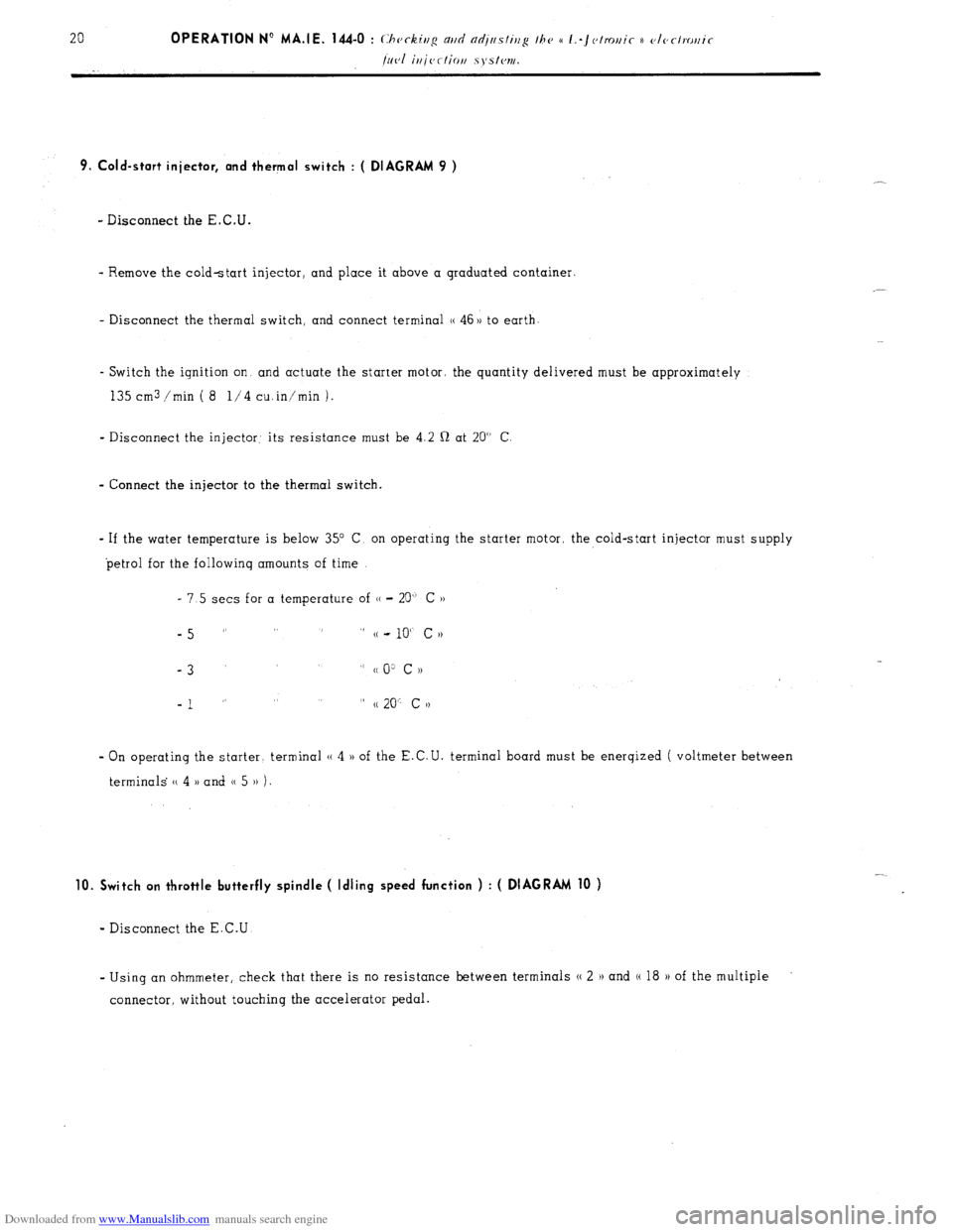
Downloaded from www.Manualslib.com manuals search engine 9. Cold-start injector, and thermal switch : ( DIAGRAM 9 )
- Disconnect the E.C.U.
- Remove the cold-start injector, and place it above a graduated container.
- Disconnect the thermal switch, and connect terminal (( 46 )) to earth
- Switch the ignition on and actuate the starter motor. the quantity delivered must be approximately
135 cm3 /min ( 8 l/4 cuin’min 1.
- Disconnect the injector: its resistance must be 4.2 Q at 20” C
- Connect the injector to the thermal switch.
- If the water temperature is below 35” C, on operating the starter motor, the cold-start injector must supply
petrol for the followinq amounts of time
- 7.5 sets for a temperature of (( - 20” C ))
-5 ” ” (( - 10“ c N
-3
” cc 0: c ))
-1 ” ” (( 20” c >)
- On operating the starter. terminal (( 4 )) of the E.C.U. terminal board must be enerqized ( voltmeter between
terminals (( 4 )) and 0 5 )) 1.
10. Switch on throttle butterfly spindle ( Idling speed function ) : ( DIAGRAM 10 )
- Disconnect the E.C.U
- Using an ohmmeter, check that there is no resistance between terminals N 2 H and (( 18 H of the multiple
connector, without touching the accelerator pedal.
Page 141 of 394
Downloaded from www.Manualslib.com manuals search engine DIAGRAM 9
+ Battery DIAGRAM l-0
1
i -
er
L----.
Page 142 of 394
Downloaded from www.Manualslib.com manuals search engine DIAGRAM 11
_____ -------------_--------- -------_.
‘>*
i-- _.
5!L 17. '
i'
/- . uij
-----,'
DIAGRAM 12.
-I
Air-flow sensor Switch on throttle
butterfly spindle
r----- _____ -__----------- t
Multi-stage
control, vibrator t Multiplying
stage
t m Relav
box ‘
.g Additional
2
resistors Y I
switch
Magnetically
’ I
triggered distributor Air temp Water temp sensor
sensor
Page 143 of 394
Downloaded from www.Manualslib.com manuals search engine 11. Switch on throttle butterfly spindle ( maximum power function ) ( DIAGRAM 11 )
- Disconnect the E.C.U.
- Using a battery operated ohmmeter, check there is no resistance between terminals (( 3 H and (( 18 )) of the
multiple connector board, with the accelerator pedal fully depressed
t 12. E.C.U. : ( DIAGRAM 12) +
s
*
i :
2 - Visually check the condition of the terminals ( male connectors on the E-C U., and female connectors
on the multiple connector socket ).
- With the engine running, tap lightly on the E.C.U., to detect any possible defect in the soldering ( dry
joints ).
Page 144 of 394
Downloaded from www.Manualslib.com manuals search engine ELECTRICAL CIRCUIT
-I- _ _
_ _
_ _
_ _
_
:I:
.--
-1
.-_
.-_
.-_
11 j--q
---.
---.
---.
1 r
t