Page 491 of 537

OUTLINE
OF
AIR
CONDITIONER
REFRIGERATION
SYSTEM
CONDENSER
COMPRESSOR
RECEIVER
DRYER
COOLING
UNIT
ELECTRICAL
CIRCUIT
OUTLINE
OF
AIR
CONDITIONER
The
air
conditioner
consists
es
sentially
of
a
cooling
unit
compressor
condenser
receiver
dryer
and
piping
The
cooling
unit
secured
with
three
brackets
is
a
ttached
to
the
location
occupied
by
the
package
tray
in
the
dash
panel
The
cooled
air
from
the
duct
is
directed
into
the
passenger
compart
Air
Conditioning
DESCRIPTION
CONTENTS
AC
2
AC3
AC
3
AC3
AC4
AC4
AC
5
DESCRIPTION
MAIN
RELAY
FAN
SWITCH
THERMO
SWITCH
PRESSURE
SWITCH
COMPRESSOR
RELAY
F
I
C
D
SOLENOID
VALVE
AC
5
AC
7
AC
7
AC
7
AC
7
AC
7
AC
7
ment
through
the
three
outlets
at
the
instrument
panel
The
compressor
serves
to
compress
the
vaporized
refrigerant
and
is
attach
ed
through
the
bracket
to
the
loca
tion
occupied
by
the
mechanical
fuel
pump
on
the
engine
The
condenser
cools
the
compres
sed
refrigerant
vapor
sent
by
the
com
pressor
and
is
located
on
the
front
of
the
radiator
in
the
engine
compart
ment
The
receiver
dryer
serving
as
a
reservoir
for
storage
of
the
liquid
sent
by
the
condenser
is
located
on
the
right
in
the
engine
compartment
The
piping
consists
of
two
flexible
hoses
and
five
copper
tubes
which
connect
various
components
of
the
air
conditioning
system
I
Cooling
unit
2
Expansion
valve
3
Receiver
dryer
4
Comressor
5
Condenser
6
Duct
@
Flexible
hose
@
Copper
tube
AC
2
AC724
Fig
AC
1
Cooling
system
Page 495 of 537
1
I
6
I
BA
RY
i
Air
Conditioning
BW
c
J
BW
n
B
m
00
L
ELECTRIC
FUEL
PUMP
oB
tl
b@
L
t
FROM
LIGHT
SWITCH
c
J
LW
2
L
rRL
fZP
W
I
FUSE
15A
J
D
CJ
B
1
COMPRESSOR
RELAY
B
GL
I
lL
GL1J
ILLUMINATION
CONTROL
RHEOSTAT
3
ILLUMINATION
LAMP
I
I
MAIN
RELAY
FAN
SWITCH
I
r
1
UE
H
I
I
THERMO
SWITCH
COLOR
CODE
@
IC
PRESSU
1
rlTCH
D
D
G
c
J
oc
I
m
f
F
I
C
D
SOLENOID
COMPRESSOR
FUSE
LR
I
BW
O
W
ov
J
I
IG
0
0
OVJ
AC
6
B
BW
L
LW
LR
W
G
GL
RL
Black
Black
with
white
stripe
Blue
Blue
with
white
stripe
Blue
with
red
stripe
White
Green
Green
with
blue
stripe
Red
with
blue
stripe
IG
BW
t
1
n
L
IGNITION
SWITCH
AC727
Fig
A
C
B
Wiring
diagram
of
air
conditioner
system
Page 519 of 537

Ll1
1t
W
l
THERMO
SWITCH
I
I
Air
Conditioning
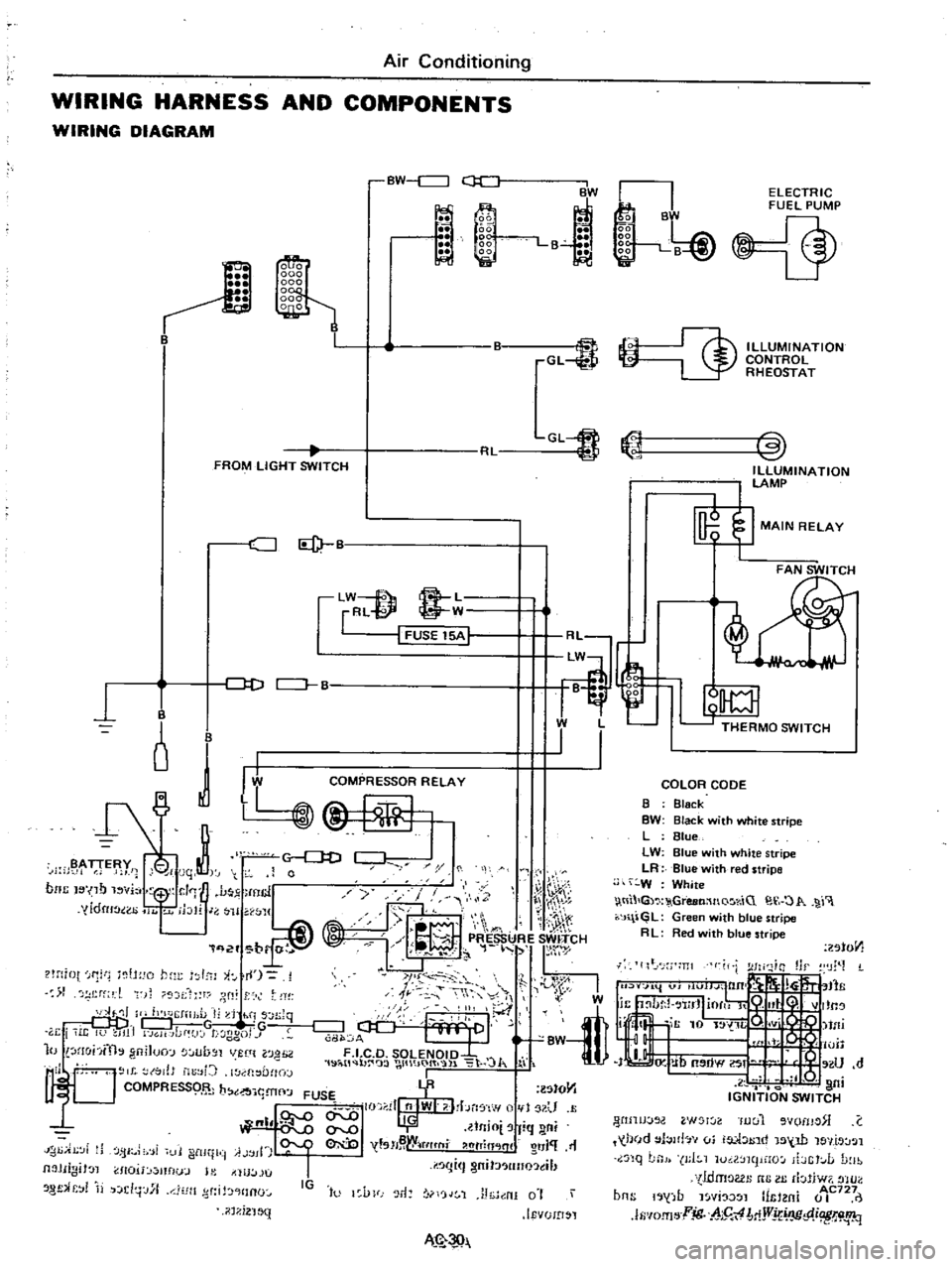
WIRING
HARNESS
AND
COMPONENTS
WIRING
DIAGRAM
BW
c
J
ii
1
l
BW
La
GL
FROM
LIGHT
SWITCH
CJ
Id
lW
f
8
L
rRl
@
W
I
FUSE
15A
1
J
D
CJ
B
B
o
J
I
B
y
i
jqt
0
noc
I
no
vi
1
J
mcl
y
yldru
ao
11
jblr
J
H
WJ1
q
2f
br
r
t
lH
iot
f1
tH
o
hm
I
l
i
I
1
rf
l
t
f
r
dt
ll
II
h
J
IiJ
l
I
d
hi
s
n
Jq
DDj
G
w
TG
r
i
i
It
U
JI1
GH
Jdf
J
t
ggo
J
10
lHohfth
gniJuo
lUb
Jl
VUlt
l0
H
2
1
19
i
tl
b
wt
IO
t
l
lo
J
I
l
l
to
tJ
b
YR
lStO
Y1
1
t
J
I
FUSE
I
II
nlWI
I
bn
f
w
1
U
QI
llnio
fiq
ni
I
tsH
W
tflt
fli
htTin
lnl
O
J
11
IJ
i
Ji
fjI
i
i
11
i
ltll
ii
A
jll
I
I
I
gm
J
lIno
tl
Jl
JIIgiJ
l
1I0U
mflu
J
l
tllU
lJU
8
f
r
j
d
j
J
l1
Jlt
d
HInO
IG
to
l
VFJ
r1
rjJ
1
J
h
nI
0
i
IEvUID
l
il
1
i2
1
MN
k
B
gg
liii
gg
1
B
J
Ii
i
ELECTRIC
FUEL
PUMP
@
ILLUMINATION
CONTROL
RHEOSTAT
COLOR
CODE
B
Black
BW
Black
with
white
stripe
L
Blue
LW
Blue
with
white
stripe
LR
Blue
with
red
stripe
W
White
tll
G
GreeMnQ
r
iC
O
1
r
J
l
GL
Green
with
blue
stripe
R
L
Red
ith
blue
stripe
201011
lIt
J
m
I
W
tfli
I
o
lUll
IJ
Ub
OW
If
U
d
l
Q
I
ni
IGNITION
SWITCH
WIJIJJOO
W
l
Iuul
vomo
C
held
l
Jlb
vi
ia
1
1
tnd
15
W
le
llt
J
l
nq
LnJ
J
I
1
luil
mpHO
ibGt
L
D
lb
tldmoGl
nG
III
rbliw7
tHO
b
b
1
AC727
ns
1
j
fJ
l
YI
l
mtl
m
0
I
lfi
IO
fI
l
jg
h5
4
MjVj
IJC
p
i
W
i
1q