Page 513 of 537
Air
Conditioning
BLOWER
MOTOR
DIAGNOSES
Blower
motor
inoperative
Check
fuse
In
fuse
block
15A
W
Single
fuse
15A
at
cooling
unit
I
j
If
OK
Check
the
continuity
and
fitting
of
fan
switch
I
I
If
OK
I
I
Connect
fan
switch
to
wiring
harness
2
Turn
the
ignition
switch
ON
IG
3
Set
fan
switch
at
ON
1
2
or
3
position
Check
the
voltage
for
blower
motor
Blue
lead
wire
is
poweI
source
Blue
wire
with
white
stripe
is
for
grounding
I
I
Voltage
I
I
Check
the
continuity
and
fitting
of
resistance
on
cooling
unit
I
I
If
OK
If
damaged
I
I
Replace
blower
motor
Replace
resistance
AC
24
mown
fuse
Replace
fuse
j
If
damaged
I
I
Replace
fan
switch
No
voltage
Replace
main
relay
Page 519 of 537

Ll1
1t
W
l
THERMO
SWITCH
I
I
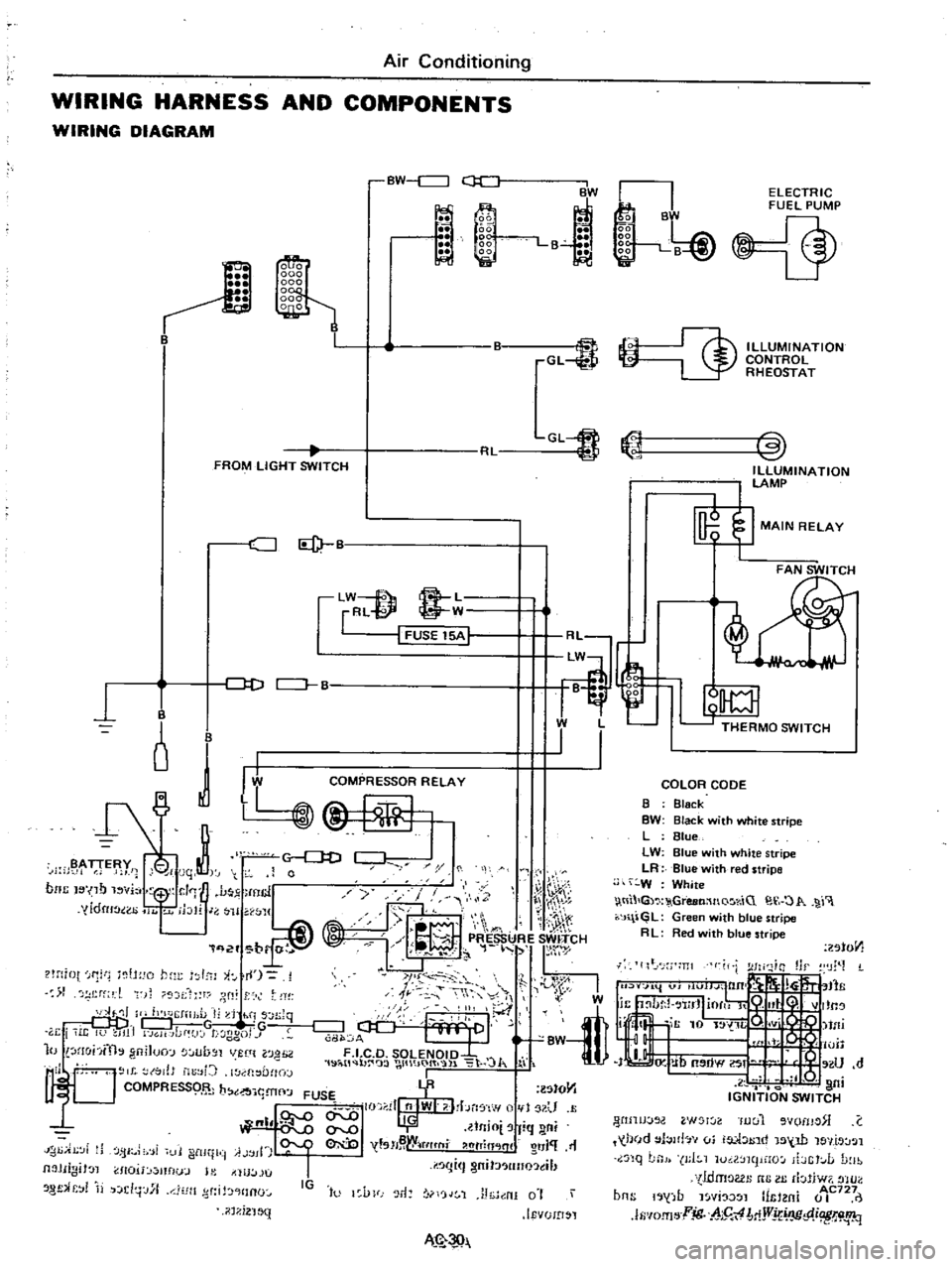
Air
Conditioning
WIRING
HARNESS
AND
COMPONENTS
WIRING
DIAGRAM
BW
c
J
ii
1
l
BW
La
GL
FROM
LIGHT
SWITCH
CJ
Id
lW
f
8
L
rRl
@
W
I
FUSE
15A
1
J
D
CJ
B
B
o
J
I
B
y
i
jqt
0
noc
I
no
vi
1
J
mcl
y
yldru
ao
11
jblr
J
H
WJ1
q
2f
br
r
t
lH
iot
f1
tH
o
hm
I
l
i
I
1
rf
l
t
f
r
dt
ll
II
h
J
IiJ
l
I
d
hi
s
n
Jq
DDj
G
w
TG
r
i
i
It
U
JI1
GH
Jdf
J
t
ggo
J
10
lHohfth
gniJuo
lUb
Jl
VUlt
l0
H
2
1
19
i
tl
b
wt
IO
t
l
lo
J
I
l
l
to
tJ
b
YR
lStO
Y1
1
t
J
I
FUSE
I
II
nlWI
I
bn
f
w
1
U
QI
llnio
fiq
ni
I
tsH
W
tflt
fli
htTin
lnl
O
J
11
IJ
i
Ji
fjI
i
i
11
i
ltll
ii
A
jll
I
I
I
gm
J
lIno
tl
Jl
JIIgiJ
l
1I0U
mflu
J
l
tllU
lJU
8
f
r
j
d
j
J
l1
Jlt
d
HInO
IG
to
l
VFJ
r1
rjJ
1
J
h
nI
0
i
IEvUID
l
il
1
i2
1
MN
k
B
gg
liii
gg
1
B
J
Ii
i
ELECTRIC
FUEL
PUMP
@
ILLUMINATION
CONTROL
RHEOSTAT
COLOR
CODE
B
Black
BW
Black
with
white
stripe
L
Blue
LW
Blue
with
white
stripe
LR
Blue
with
red
stripe
W
White
tll
G
GreeMnQ
r
iC
O
1
r
J
l
GL
Green
with
blue
stripe
R
L
Red
ith
blue
stripe
201011
lIt
J
m
I
W
tfli
I
o
lUll
IJ
Ub
OW
If
U
d
l
Q
I
ni
IGNITION
SWITCH
WIJIJJOO
W
l
Iuul
vomo
C
held
l
Jlb
vi
ia
1
1
tnd
15
W
le
llt
J
l
nq
LnJ
J
I
1
luil
mpHO
ibGt
L
D
lb
tldmoGl
nG
III
rbliw7
tHO
b
b
1
AC727
ns
1
j
fJ
l
YI
l
mtl
m
0
I
lfi
IO
fI
l
jg
h5
4
MjVj
IJC
p
i
W
i
1q
Page 521 of 537

Inspection
Check
continuiry
in
fan
switch
circuit
with
a
test
lamp
or
an
ohm
meter
I
011
I
2
3
ICD
Tt
tt
AC772
Fig
AC
45
Fan
switch
RESISTOR
FOR
FAN
SWITCH
Removal
and
Installation
I
Disconnect
battery
ground
cable
2
Remove
glove
box
3
Remove
cooling
unit
Refer
to
Removal
and
Installation
under
Cooling
Unit
4
Disconnect
resistor
lead
wires
at
connector
@
O
sn
I
3n
CD
00
@
AC492
Fig
AC
46
Resistor
for
fan
switch
Air
Conditioning
5
Remove
resistor
assembly
from
upper
side
of
cooling
unit
Resistor
is
inserted
into
case
6
To
install
res
istor
for
fan
switch
reverse
the
order
of
removaL
Inspection
Test
continuity
between
resistor
and
fuse
THERMO
SWITCH
Removal
and
installation
1
Disconnect
battery
ground
cable
2
Remove
glove
box
3
Remove
duct
from
cooling
unit
4
Disconnect
thermo
switch
control
cable
and
lead
wires
5
Remove
thermo
switch
Note
Capillary
lube
is
fitted
into
groove
in
cooler
unit
6
To
install
thermo
switch
reverse
the
order
of
removal
I
I
AC773
Fig
AC
47
Removing
thermo
switch
AC
32
Inspection
I
Fully
move
thermo
swirch
lever
to
COLD
2
Test
continuity
between
ter
minals
with
a
test
tamp
or
an
ohm
meter
Continuity
should
exist
3
Dip
capillary
tube
end
into
ice
water
Test
continuity
between
ter
minals
Continuity
should
not
exist
4
Replace
if
switch
is
found
dam
aged
F
I
C
D
SOLENOID
VALVE
Removal
and
installation
I
Disconnect
battery
ground
cable
2
Disconnect
lead
wires
and
vacu
um
tube
3
Remove
two
screws
securing
sole
noid
valve
and
remove
solenoid
valve
AC77
4
Fig
AC
48
Removing
F
l
C
D
solenoid
valve
4
To
install
solenoid
valve
reverse
the
order
of
removal
Inspection
1
Test
continuity
in
solenoid
valve
circuit
with
a
test
lamp
or
an
ohm
meter
2
Turn
both
fan
switch
and
thermo
switch
on
3
Run
engine
at
idle
and
check
to
be
sure
that
vacuum
is
present
in
line
between
solenoid
valve
and
diaphragm