1977 DATSUN PICK-UP oil level
[x] Cancel search: oil levelPage 317 of 537

Automatic
Transmission
LINE
PRESSURE
GOVERNOR
FEED
PRESSURE
At
cut
back
point
After
cut
back
Throttle
opening
under
approximately
over
approximately
15
kmfh
10
MPH
35
kmfh
22
MPH
Unit
mmHg
Unit
kgfcm2
psi
Unit
kgfcm2
psi
Full
throtlle
0
9
4
to
11
0
134
to
156
5
5
to
6
5
78
to
92
Minill1um
throttle
450
3
0
to
4
0
43to
57
3
0
to
4
0
43
to
57
Fulllhrotlle
0
10
0
to
12
0
142
to
171
5
5
to
7
0
78
to
100
Minimum
throttle
450
6
0
to
12
0
85to171
5
5
to
7
0
78
to
100
Full
throtlle
0
14
0
to
16
0
199
to
228
14
0
to
16
0
199
to
228
Minimum
throttle
450
3
0
to
5
5
43
to
78
3
0
to
5
5
4
lo
78
Range
D
2
R
Notes
a
The
line
pressure
during
idling
corresponds
to
the
oil
pressure
before
cut
down
at
minimum
throttle
b
The
oil
pressure
After
cut
back
means
that
after
the
pressure
modifier
valve
has
operated
JUDGEMENT
IN
MEASURING
LINE
PRESSURE
Low
idling
line
pressure
in
the
ranges
D
2
I
R
and
pH
This
can
be
atlributed
to
trouble
in
the
pressure
supply
system
or
too
low
output
of
power
caused
by
I
A
worn
oil
pump
2
An
oil
pressure
leak
in
the
oil
pump
valve
body
or
case
3
A
sticking
regulator
valve
2
Low
idling
line
pressure
in
cer
tain
ranges
only
This
is
presumably
caused
by
an
oil
leak
in
the
devices
or
circuits
con
nected
to
the
relevant
ranges
I
When
there
is
an
oil
leak
in
the
rear
clutch
and
governor
the
line
pressure
in
D
2
and
I
are
low
but
the
pressure
is
norrrial
in
R
2
When
an
oil
leak
occurs
in
the
low
and
reverse
brake
circuit
the
line
pressure
in
R
and
P
are
low
but
the
pressure
is
normal
in
D
2
and
I
3
High
idling
line
pressure
This
is
presumably
caused
by
an
increased
vacuum
throttle
pressure
owing
to
a
leak
in
the
vacuum
tube
or
dia
phragm
or
by
an
increased
line
pressure
due
to
a
sticking
regulator
valve
Vacuum
leakage
is
checked
by
directly
measuring
the
negative
pres
sure
after
removing
the
vacuum
pipe
A
puncture
of
the
vacuum
dia
phragm
can
be
easily
ascertained
because
the
torque
converter
oil
is
absorbed
into
the
engine
and
the
exhaust
pipe
emits
white
smoke
4
Items
to
be
checked
when
the
line
pressure
is
increasing
In
this
check
the
line
pressure
should
be
measured
with
vacuums
of
450
mmHg
and
0
mmHg
in
accordance
with
the
stall
test
procedure
I
If
the
line
pressure
do
not
n
crease
despite
the
vacuum
decrease
check
whether
the
vacuum
rod
is
incorporated
2
If
the
line
pressure
do
not
meet
the
standard
it
is
caused
mostly
by
a
sticking
pressure
regulating
valve
pres
sure
regulating
valve
plug
or
amplifier
TROUBLE
SHOOTING
CHART
INSPECTING
ITEMS
1
Inspection
with
automatic
trans
mission
on
vehicle
AT
53
A
Oil
level
B
Ra
lge
select
linkage
C
Inhibitor
switch
and
wiring
D
Vacuum
diaphragm
and
piping
E
Downshift
solenoid
kickdown
switch
and
wiring
F
Engine
idling
rpm
G
Oil
pressure
throttle
H
Engine
stall
rpm
I
Rear
lubrication
J
Control
valve
manual
K
Governor
valve
L
Band
servo
M
Transmission
air
check
N
Oil
quantity
o
Ignition
switch
and
starter
motor
P
Engine
adjustment
and
brake
in
spection
2
Inspection
after
inspecting
auto
matic
transmission
on
vehicle
m
Rear
clutch
n
Front
clutch
q
Band
brake
r
Low
and
reverse
brake
s
Oil
pump
t
Leakage
of
oil
passage
u
One
way
clutch
of
troque
coilVerter
v
One
way
clutch
of
transmission
w
Front
clutch
check
ball
x
Parking
linkage
y
Planetary
gear
Page 321 of 537

Automatic
Transmission
TROUBLE
SHOOTING
GUIDE
FOR
3N71B
AUTOMATIC
TRANSMISSION
Order
Test
item
Checking
Oil
level
gauge
2
Downshift
solenoid
3
Manuallinkage
L
4
Inhibitor
switch
5
Engine
idling
rpm
6
Vacuum
pressure
of
vacuum
pipe
7
Operation
in
each
range
8
Creep
of
vehicle
Stall
test
I
Oil
pressure
before
tesling
1
2
Stall
test
3
Oil
pressure
after
testing
Road
test
Slow
acceleration
I
st
2nd
2nd
3rd
2
Quick
acceleration
lst
2nd
2nd
3rd
3
Kick
down
operation
3rd
2nd
or
2nd
1st
Procedure
Check
gauge
for
oil
level
and
leakage
before
and
after
each
test
Check
for
sound
of
operating
solenoid
when
depressing
accelerator
pedal
fully
with
ignition
key
ON
Check
by
shifting
into
P
lR
IN
D
2
and
I
ranges
with
selector
lever
Check
whether
starter
operates
in
N
and
p
ranges
only
and
whether
reverse
lamp
operates
in
R
range
only
Check
whelher
idling
rpm
meet
standard
Check
whether
vacuum
pressure
is
more
than
450
mmHg
in
idling
and
whether
it
decreases
with
increasing
rpm
Check
whether
transmission
engages
positively
by
shifting
N
0
N
2
N
l
I
and
N
R
range
while
idling
with
brake
applied
Check
whether
there
is
any
creep
in
D
2
R
ranges
and
Measure
line
pressures
in
D
2
I
and
R
range
while
idling
Measure
engine
rpm
and
line
pressure
in
D
2
I
and
R
ranges
during
full
throttle
operati
n
Notes
a
Temperature
of
torque
converter
oil
used
in
test
should
be
from
600
to
1000C
1400
to
2120F
i
e
sufficiently
warmed
up
but
not
overheated
b
To
cool
oil
between
each
stall
test
for
D
2
I
and
R
ranges
idle
engine
i
e
rpm
at
about
1
200
rpm
for
more
than
1
minute
in
P
range
Measurement
time
must
not
be
more
than
5
seconds
Same
as
item
I
Check
vehide
speeds
and
engine
cpm
in
shifting
up
Ist
2nd
range
and
2nd
Jo3rd
range
while
running
with
lever
in
D
range
and
engine
vacuum
pressure
of
about
200
I11I1lHg
Same
as
item
1
above
except
with
engine
vacuum
pressure
of
0
mmHg
i
e
in
position
just
before
kickdown
Check
whether
the
kickdown
operates
and
measure
the
time
delays
while
running
at
30
40
50
60
70
km
h
18
25
30
37
43
MPH
in
D3
range
AT
57
Page 360 of 537

Note
When
installing
fulcrum
pin
insert
it
from
rearward
of
vehicle
12
Install
tension
rod
shock
ab
sorber
I
stabilizer
torsion
bar
spring
and
knuckle
arm
referring
to
the
related
paragraphs
13
Install
brake
disc
to
knuckle
spindle
and
torque
securing
bolt
to
4
2
to
5
0
kg
m
30
to
36
ft
Ib
14
Install
wheel
and
brake
drum
as
an
assembly
and
torque
knuckle
spin
dle
nut
to
8
0
to
9
0
kg
m
58
to
65
ft
Ib
DISASSEMBLY
AND
ASSEMBLY
Upper
link
I
Detach
upper
link
spindle
from
upper
links
and
remove
clamp
dust
cover
and
dust
seal
Secure
upper
link
in
a
vise
and
loosen
screw
bushing
Assemble
link
spindle
in
reverse
sequence
to
disassembling
noting
the
following
instructions
2
Torque
screw
bushing
on
upper
link
to
3S
to
55
kg
m
253
to
398
ft
Ib
Install
new
dust
seal
and
dust
cover
and
secure
them
with
clamp
3
Coat
grease
to
screw
bushing
in
side
and
the
thread
portion
of
upper
link
spindle
liberally
Screw
front
and
rear
links
to
upper
link
spindle
in
the
same
length
so
as
to
obtain
the
speci
fied
figures
as
shown
in
Figure
FA
23
Unit
mm
in
I
44
6
1
156
FA2
Upper
link
and
upper
link
spindle
Fig
FA
23
Front
Axle
Front
Suspension
4
Make
sure
to
operate
upper
link
spindle
smoothly
after
installation
5
Replace
filler
plug
with
grease
nipple
and
pack
grease
until
grease
comes
out
from
dust
cover
Reinstall
f1ller
plug
Lower
link
When
installing
torque
arm
on
lower
link
tighten
it
to
the
following
specifications
Serration
boss
1
8
to
2
6
kg
m
13
to
19
ft
Ib
Arm
head
2
7
to
3
7
kg
m
20
to
27
ft
tb
INSPECTION
Upper
link
spindle
fulcrum
pin
and
screw
bushing
Apply
screw
bushing
to
upper
link
spindle
or
fulcrum
pin
and
measure
axial
end
play
between
them
When
the
end
play
exceeds
0
35
mm
0
0138
in
replace
upper
link
spindle
or
fulcrum
pin
together
with
screw
bushings
Condition
Vehicle
empty
no
payload
Vehicle
loaded
Notes
a
Vehicle
empty
no
payload
consists
of
the
following
conditions
I
Full
tank
of
gasoline
radiator
f1lled
and
engine
oil
level
full
2
Spare
tire
wheel
jack
and
jack
handle
in
design
position
b
Vehicle
loaded
consists
of
the
fol
lowing
conditions
For
all
models
2
persons
and
SIlO
leg
I
103lb
payload
FA
Check
the
screw
of
upper
link
spindle
fulcrum
pin
and
screw
bush
ing
and
repair
or
replace
if
necessary
Note
Discard
dust
cover
and
dust
seal
when
disassembled
ADJUSTMENT
VEHICLE
POSTURE
Vehicle
posture
may
be
incorrect
due
to
weakened
spring
or
other
faulty
condition
The
following
procedures
are
necessary
when
adjustment
is
Ie
quired
That
is
the
vehicle
posture
can
be
adjusted
by
obtaining
only
the
speci
fied
H
dimension
changing
the
length
of
anchor
bolt
I
Raise
front
of
vehicle
on
stands
2
Adjust
H
dimension
with
turn
ing
nut
adjusting
anchor
bolt
H
dimension
changes
approximately
3
5
mm
0
J38
in
vertically
when
adjust
nut
is
turned
one
complete
turn
3
To
make
the
best
vehicle
posture
H
dimension
must
be
in
the
follow
ing
range
H
dimension
mOl
in
All
models
79
to
84
3
11
to
3
31
54
5
2
15
o
i
Fig
FA
24
FA242
Dimension
for
standard
vehicle
postl4re
Page 364 of 537
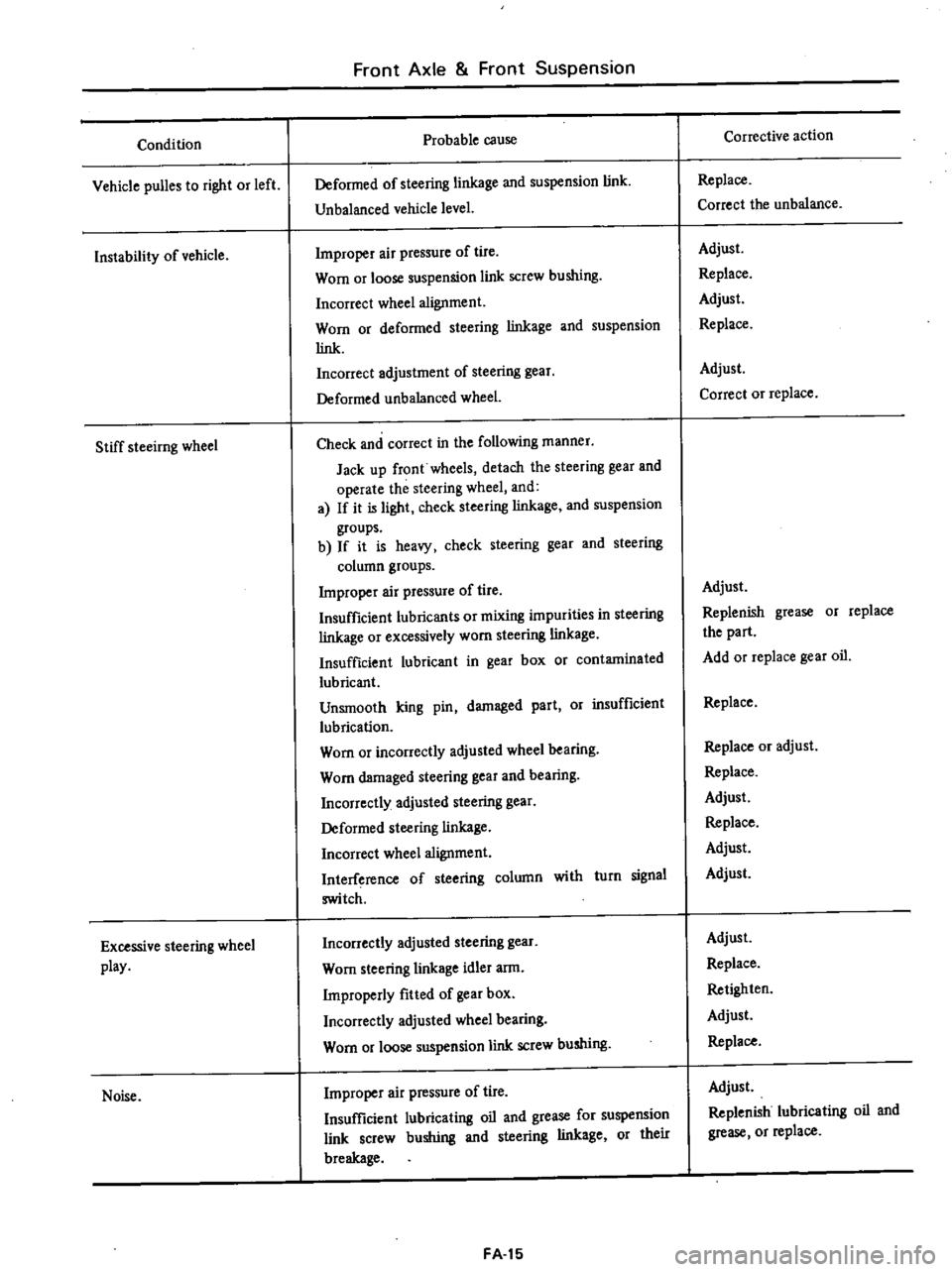
Condition
Vehicle
puBes
to
right
or
left
Instability
of
vehicle
Stiff
steeirng
wheel
Excessive
steering
wheel
play
Noise
Front
Axle
Front
Suspension
Probable
cause
Deformed
of
steering
linkage
and
suspension
link
Unbalanced
vehicle
level
Improper
air
pressure
of
tire
Worn
or
loose
suspension
link
screw
bushing
Incorrect
wheel
alignment
Worn
or
deformed
steering
linkage
and
suspension
link
Incorrect
adjustment
of
steering
gear
Deformed
unbalanced
wheel
Check
and
correct
in
the
following
manner
Jack
up
front
wheels
detach
the
steering
gear
and
operate
the
steering
wheel
and
a
If
it
is
light
check
steering
linkage
and
suspension
groups
b
If
it
is
heavy
check
steering
gear
and
steering
column
groups
Improper
air
pressure
of
tire
Insufficient
lubricants
or
mixing
impurities
in
steering
linkage
or
excessively
worn
steering
linkage
Insufficient
lubricant
in
gear
box
or
contaminated
lubricant
Unsmooth
king
pin
damaged
part
Or
insufficient
lubrication
Worn
or
incorrectly
adjusted
wheel
bearing
Worn
damaged
steering
gear
and
bearing
Incorrectly
adjusted
steering
gear
Deformed
steering
linkage
Incorrect
wheel
alignment
Interference
of
steering
column
with
turn
signal
switch
Incorrectly
adjusted
steering
gear
Worn
steering
linkage
idler
arm
Improperly
fitted
of
gear
box
Incorrectly
adjusted
wheel
bearing
Worn
or
loose
suspension
link
screw
bushing
Improper
air
pressure
of
tire
Insufficient
lubricating
oil
and
grease
for
suspension
link
screw
bushing
and
steering
linkage
or
their
breakage
FA
15
Corrective
action
Replace
Correct
the
unbalance
Adjust
Replace
Adjust
Replace
Adjust
Correct
or
replace
Adjust
Replenish
grease
or
replace
the
part
Add
or
replace
gear
oil
Replace
Replace
or
adjust
Replace
Adjust
Replace
Adjust
Adjust
Adjust
Replace
Retighten
Adjust
Replace
Adjust
Replenish
lubricating
oil
and
grease
or
replace
Page 397 of 537

Condition
Excessive
pedal
travel
Spongy
pedal
Poor
braking
effect
Brakes
drag
Brake
Syst
em
TROUBLE
DIAGNOSES
AND
CORRECTIONS
Probable
cause
Low
brake
1uid
level
or
empty
master
cylinder
reservoir
Leakage
in
master
cylinder
Deteriorated
check
valve
Air
in
system
Faulty
brake
adjustment
Low
1uid
level
in
master
cylinder
Air
in
system
Faulty
brake
adjustment
Reservoir
filler
cap
vent
hole
clogged
Swollen
hose
due
to
deterioration
or
use
of
poor
quality
hose
Distorted
brake
shoes
or
excessively
worn
or
cracked
brake
drum
Soft
or
swollen
caliper
seals
Use
of
a
brake
1uid
with
too
low
boiling
point
Fluid
leakage
in
brake
lines
Low
brake
1uid
level
or
empty
master
cylinder
reservoir
Air
in
brake
lines
Excessive
shoe
ta
drum
clearance
Grease
oil
mud
or
water
on
linings
or
pads
Deterioration
of
linings
or
pads
Local
fit
of
linings
or
pads
Linings
or
pads
excessively
worn
Master
cylinder
or
wheel
cylinders
in
poor
condition
Binding
mechanical
linkage
at
brake
pedal
and
shoes
Clogged
brake
lines
Incorrect
adjustment
of
wheel
bearings
Improper
shoe
t
drum
clearance
Weak
shoe
return
springs
No
free
travel
in
brake
shoe
return
BR
22
Corrective
action
Fill
and
bleed
as
necessary
Test
for
source
of
leakage
by
examining
all
lines
connec
tions
and
wheel
cylinder
Overhaul
master
cylinder
Replace
check
valve
and
bleed
system
Bleed
system
Adjust
shoe
to
drum
clearance
Inspect
auto
adjuster
operation
Top
with
1uid
and
inspect
for
leakage
Correct
as
necessary
Adjust
shoe
to
drum
clearance
Inspect
aut
adjuster
operation
Clean
and
bleed
system
Replace
hose
and
bleed
system
Replace
faulty
parts
Drain
hydraulic
system
flush
with
alcohol
and
replace
all
seals
Replace
with
specified
brake
1uid
and
bleed
system
Check
master
cylinder
pIpIng
and
wheel
cylinder
for
leaks
and
repair
Fill
and
bleed
as
necessary
Bleed
system
Adjust
Clean
brake
mechanism
and
check
for
cause
of
problem
Replace
linings
or
pads
Replace
Shave
or
replace
Replace
Repair
or
replace
Free
up
as
required
Check
and
clean
Adjust
or
repair
Adjust
Replace
Adjust
pedal
height
Page 428 of 537

CAB
BODY
Body
Frame
Ist
mounting
2nd
mounting
1
Bolt
2
Plain
washer
3
Rubber
washer
4
Upper
rubber
5
Bottom
rubber
6
Plain
w
er
7
Upper
washer
8
Lower
washer
1st
mounting
REMOVAL
AND
INSTALLATION
Remove
battery
from
engine
compartment
2
Disconnect
oil
cooler
hoses
from
radiator
automatic
transmission
model
only
3
Disconnect
air
conditioner
tubes
from
condenser
if
so
equipped
4
Drain
water
from
cooling
system
completely
and
remove
radiator
and
condenser
if
so
equipped
5
Remove
engine
hood
from
hood
hinges
after
scribing
hood
for
rein
stallation
6
Remove
bumper
stay
from
frame
and
remove
front
bumper
7
Remove
radiator
grille
8
With
the
aid
of
Steering
Wheel
Puller
ST27
180001
remove
steering
wheel
from
steering
shaft
9
Remove
steering
gear
arm
from
steering
sector
shaft
using
suitable
puller
10
Remove
screws
securing
steering
shaft
dust
seat
and
insulator
in
posi
tion
2nd
mounting
3rd
mounting
II
Remove
steering
gear
housing
from
frame
and
pull
it
out
into
engine
compartment
12
Disconnect
speedometer
cable
at
transmission
1
3
Disconnect
carbon
canister
hoses
between
canister
to
vacuum
gallery
and
canister
to
intake
manifold
at
canister
14
Disconnect
air
pump
to
air
pump
air
cleaner
hose
at
air
cleaner
15
Disconnect
air
conditioner
hoses
from
compressor
if
so
equipped
16
Disconnect
air
cleaner
duct
from
body
17
Disconnect
Master
Vac
vacuum
hose
at
intake
manifold
18
Remove
snap
ring
and
control
lever
pin
from
transmission
striking
guide
and
remove
control
lever
19
Disconnect
fuel
hoses
at
fuel
strainer
20
Disconnect
fuel
return
hose
and
evaporation
hose
at
connectors
21
Disconnect
brake
and
clutch
tubes
from
each
master
cylinder
22
Remove
all
clips
securing
fuel
tubes
brake
tubes
and
clutch
tube
at
cab
body
BF
4
BF472A
Unit
mm
in
Fig
BF
4
Cab
body
mountings
23
Loosen
hand
brake
control
cable
at
brake
control
lever
Then
discon
nect
cable
from
dash
panel
Note
Place
blocks
against
front
and
rear
wheels
to
prevent
vehicle
from
rolling
off
accidentally
24
Free
accelerator
wire
from
car
buretor
25
Disconnect
heater
hoses
at
engine
side
26
Disconnect
wire
harnesses
from
related
engine
electrical
parts
27
Disconnect
engine
and
chassis
harnesses
at
their
connection
on
right
sidemember
near
rear
engine
mounting
member
28
Remove
six
bolts
securing
body
to
frame
29
With
the
use
of
suitable
ropes
and
an
overhead
hoist
lift
cab
body
straight
up
slowly
and
place
it
on
a
level
surface
Note
In
lifting
up
cab
body
use
care
not
to
dash
it
against
engine
or
rear
body
Cab
body
weighs
approxi
mately
220
kg
485
Ib
Page 451 of 537

To
adjust
vertical
aim
use
adjusting
screw
on
upper
side
of
headlamp
and
to
adjust
horizontal
aim
use
adjusting
screw
on
side
of
head
lamp
Notes
Before
making
headlarnp
aiming
ad
justment
observe
the
foUowing
in
structions
Body
Electrical
System
a
Keep
aU
tires
inflated
to
correct
pressures
b
Place
vehicle
and
tester
on
the
same
flat
surface
c
See
that
there
is
no
load
in
vehicle
I
Gasoline
radiator
and
engine
oil
pan
filled
up
to
correct
levels
2
Without
passenger
When
performing
headlamp
aiming
adjustment
use
an
aiming
device
aiming
wall
screen
or
headlamp
tester
For
operating
instructions
of
any
aimer
refer
to
respective
operation
manuals
supplied
with
the
unit
DRIVING
BEAM
HIGH
BEAM
L
wt
H
G
hi
i
iiI
PASSING
BEAM
LOW
BEAM
10
m
32
8
ft
W2
H2
10
m
02
8
n
d
20
h2
I
02
I
I
f
10
m
32
8
ft
Driving
beam
High
beam
Passing
beam
Low
beam
HI
WI
01
mm
mm
CO
in
in
I
715
780
48
All
models
28
15
30
71
hI
H2
W2
h2
O2
d
mm
mm
mm
in
in
in
0
140
I
715
11
160
12018
5
51
28
15
45
67
mm
mm
in
in
392
349
is
43
13
74
BE302
Fig
BE
8
Aiming
adjustment
BE
6
Page 461 of 537

REMOVAL
AND
INSTALLATION
I
Disconnect
battery
ground
cable
2
Working
through
meter
openings
of
cluster
lid
remove
three
screws
retaining
cluster
lid
to
instrument
panel
3
From
underneath
instrument
panel
remove
one
screw
retaining
me
ter
assembly
to
lower
panel
of
instru
ment
4
Withdraw
cluster
lid
slightly
For
ccess
to
switches
knobs
etc
follow
the
procedures
given
in
each
section
5
From
behind
combination
meter
disconnect
speedometer
cable
at
speedometer
head
and
multiple
con
nector
instrume
nt
wire
assembly
from
printed
circuit
6
On
vehicle
with
clock
disconnect
wires
at
each
connection
on
meter
printed
circuit
7
Remove
four
screws
retaining
me
ter
assembly
to
cluster
lid
8
Remov
combination
meter
as
sembly
9
When
installing
combination
me
ter
assembly
follow
the
reverse
se
quence
of
removal
Fig
BE
23
Removing
eluster
lid
SPEEDOMETER
REMOVAL
AND
INSTALLATION
1
Remove
combination
meter
as
sembly
Follow
the
procedures
under
Removal
and
Installation
in
Combina
tion
Meter
Body
Electrical
System
2
Remove
meter
front
cover
and
shadow
plate
by
removing
clips
and
screws
3
Remove
screws
retaining
speed
ometer
to
printed
circuit
housing
and
remove
speedometer
4
Install
speedometer
in
the
reverse
sequence
of
removal
ODOMETER
SWITCH
REMOVAL
AND
INSTALLATION
I
Remove
speedometer
as
outlined
under
Speedometer
2
Remove
odometer
retaining
screws
3
Install
odometer
in
the
reverse
sequence
of
removal
BE342A
Fig
BE
24
Odometerswitch
FUEL
GAUGE
AND
WATER
TEMPERATURE
GAUGE
DESCRI
PTION
The
fuel
gauge
consists
of
a
tank
unit
located
in
the
fuel
tank
and
fuel
gauge
The
tank
unit
detects
fuel
level
with
its
float
converts
fuel
level
varia
tion
to
a
resistance
of
slide
resistor
installed
on
the
float
base
and
thus
controls
current
flowing
to
the
fuel
gauge
BE16
The
water
temperature
gauge
con
sists
of
a
gauge
and
thermal
transmit
ter
located
in
the
engine
block
The
thermal
transmitter
is
equipped
with
a
thermistor
element
which
converts
cooling
water
temperature
variation
to
a
resistance
and
thus
the
thermal
tr
t
c
rtrols
cUfTent
flowing
to
the
gauge
The
fuel
gauge
and
water
tempera
ture
gauge
are
provided
with
a
bi
metal
arm
and
heater
coil
When
the
ignition
switch
is
set
to
ON
current
flows
to
the
heat
coil
and
the
heat
coil
is
heated
With
this
heat
the
bi
metal
arm
is
bent
and
thus
the
pointer
connected
to
the
bi
metal
arm
is
oper
ated
The
characteristics
of
both
gauges
are
the
same
A
tolerance
may
occur
on
the
water
temperature
gauge
or
fuel
gauge
due
to
source
voltage
fluctuation
The
voltage
regulator
is
used
to
supply
a
constant
voltage
so
that
the
water
temperature
gauge
and
fuel
gauge
operate
correctly
The
operating
part
of
the
regulator
consists
of
a
bi
metal
arm
and
a
heater
coil
When
the
ignition
switch
is
turned
on
the
bi
metal
arm
is
heated
and
bent
by
the
coil
opening
the
contact
Consequently
current
to
the
coil
is
interrupted
As
the
bi
metal
cools
the
contact
closes
The
repeti
tion
of
this
operation
produces
a
pulsating
voltage
of
8
volts
which
is
applied
to
the
water
temperature
and
fuel
gauges
If
both
the
water
temperature
gauge
and
fuel
gauge
become
faulty
at
the
same
time
this
may
be
attributed
to
problem
in
the
voltage
regulator
REMOVAL
AND
INSTALLATION
1
Remove
combination
meter
as
sembly
Follow
the
procedures
under
Removal
and
Installation
in
Combina
tion
Meter
2
Remove
meter
front
cover
and
shadow
plate
by
removing
clips
and
screws
3
Remove
retaining
nuts
at
the
back
side
of
combination
meter
as
sembly
and
remove
meter
4
Install
meter
in
the
reverse
se
quence
of
removal