Page 466 of 537

Body
Electrical
System
ELECTRICAL
ACCESSORIES
CONTENTS
HORN
DESCRIPTION
REMOVAL
AND
INSTALLATION
IGNITION
SWITCH
REMOVAL
AND
INSTALLATION
INSPECTION
WINDSHIELD
WIPER
AND
WASHER
REMOVAL
AND
INSTALLATION
INSPECTION
RADIO
REMOVAL
AND
INSTALLATION
ADJUSTMENT
CLOCK
REMOVAL
I
NST
ALLA
TION
HEATER
DESCRIPTION
AIRFLOW
HEATER
UNIT
ASSEMBLY
BE
21
BE
21
BE
21
8E
n
BE
22
BE
22
BE
23
BE
23
BE
23
BE
25
BE
25
BE
25
BE
25
BE
25
BE
26
BE
26
BE
26
BE
28
BE
29
HORN
DESCRIPTION
The
horn
circuit
includes
a
horn
relay
Current
from
the
battery
flows
through
the
fusible
link
and
fuse
to
the
horn
relay
terminal
B
where
it
is
shunted
by
the
two
circuits
In
one
circuit
terminal
S
the
current
flow
is
supplied
through
the
solenoid
and
Fusible
link
Qi
att
Fu
H
I
HIBQ
t
J
JJI
L
J
Hornrelay
Qm
HEATER
CORE
FAN
MOTOR
CONTROL
ASSEMBLY
ADJUSTMENT
SPECIFICATIONS
TACHOMETER
REPLACEMENT
8UL8
REPLACEMENT
SEAT
8ELT
WARNING
SYSTEM
DESCRIPTION
REMOVAL
AND
INSTALLATION
WARNING
LAMP
BULB
REPLACEMENT
INSPECTION
TROUBLE
DIAGNOSES
AND
CORRECTIONS
HORN
WINDSHIELD
WIPER
AND
WASHER
RADIO
Horn
button
BE859A
Fig
BE
29
Circuit
diagram
of
horn
sy
tem
horn
button
to
the
ground
In
the
other
circuit
terminal
H
the
current
flow
is
supplied
through
the
relay
contacts
and
horn
Horn
bracket
serves
as
a
grounding
When
the
horn
button
is
pressed
current
from
the
battery
energizes
the
solenoid
As
the
solenoid
is
energized
the
relay
contacts
are
closed
This
allows
the
current
to
flow
to
the
horn
BE
21
REMOVAL
AND
INSTALLATION
Horn
8E
29
BE
29
BE
29
8E
29
BE
30
BE
30
BE
30
8E
30
8E
31
BE
31
BE
31
8E
31
8E
31
BE
33
8E
33
8E
34
BE
35
I
Disconnect
battery
ground
cable
2
Disconnect
horn
wire
at
terminal
on
horn
body
3
Remove
horn
retaining
bolt
4
Install
horn
in
the
reverse
se
quence
of
removal
Horn
relay
The
horn
relay
is
installed
on
the
hoodIedge
on
the
right
side
of
the
engine
compartment
I
Disconnect
battery
ground
cable
2
Disconnect
horn
relay
wire
con
nector
at
terminals
on
horn
relay
3
Remove
retaining
screws
4
Install
horn
relay
in
the
reverse
sequence
of
removal
Page 467 of 537

Body
Electrical
System
Horn
switch
The
horn
switch
is
integral
with
the
turn
signal
and
dimmer
switch
as
sembly
Remove
switch
assembly
as
outlined
in
Turn
Signal
and
Dimmer
Switch
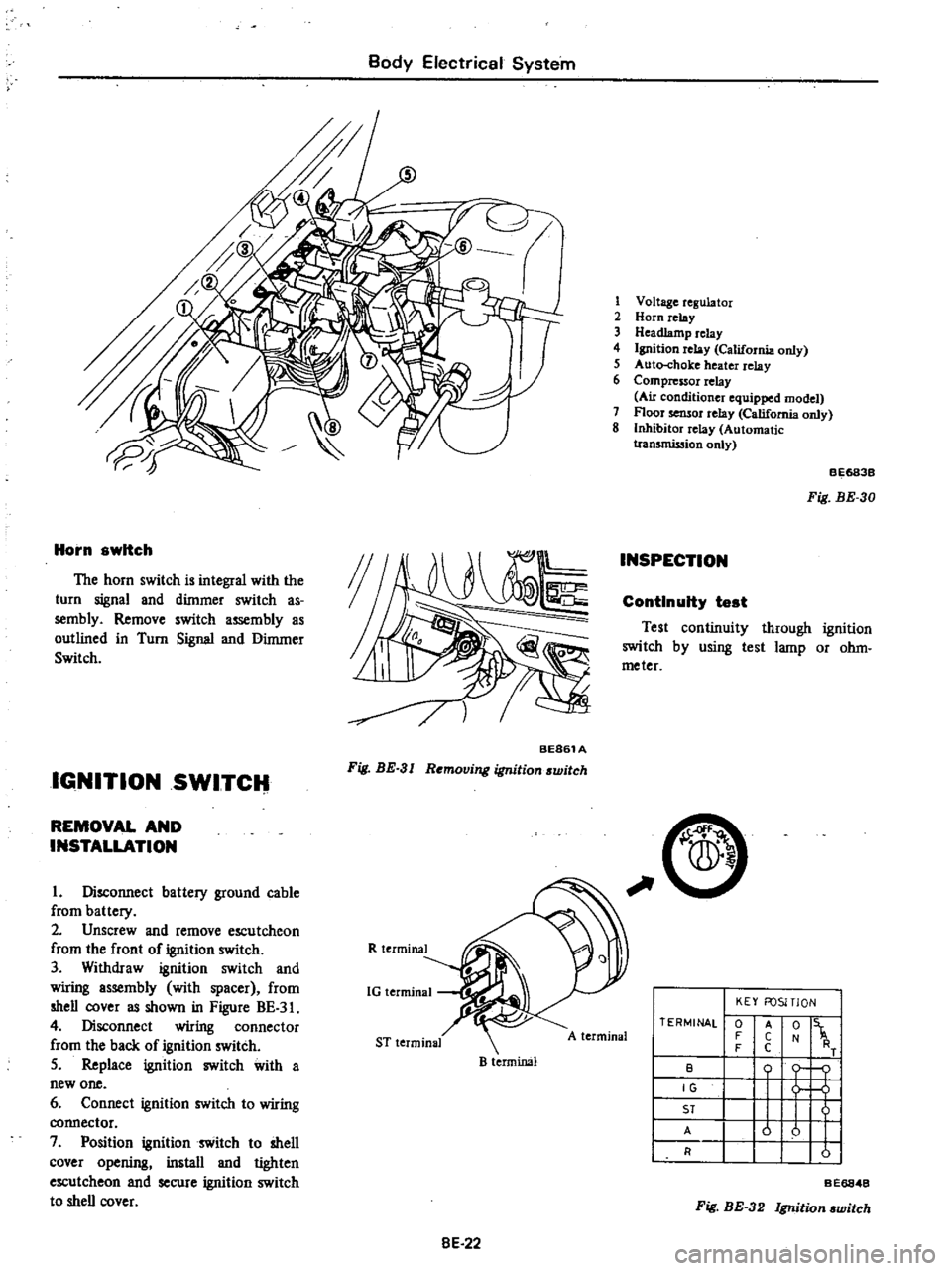
IGNITION
SWITCH
BE861A
Fig
BE
3
I
Removing
ignition
switch
REMOVAL
AND
INSTALLATION
I
Disconnect
battery
ground
cable
from
battery
2
Unscrew
and
remove
escutcheon
from
the
front
of
ignition
switch
3
Withdraw
ignition
switch
and
wiring
assembly
with
spacer
from
shell
cover
as
shown
in
Figure
BE
3
4
Disconnect
wiring
connector
from
the
back
of
ignition
switch
5
Replace
ignition
switch
with
a
new
one
6
Connect
ignition
switch
to
wiring
connector
7
Position
ignition
switch
to
shell
cover
opening
install
and
tighten
escutcheon
and
secure
ignition
switch
to
shell
cover
R
terminal
1G
terminal
ST
terminal
B
terminal
8E
22
1
Voltage
regulator
2
Horn
relay
3
Headlamp
relay
4
Ignition
relay
California
only
5
Auto
choke
heater
relay
6
Compressor
relay
Au
conditioner
equipped
model
7
Floor
sensor
relay
California
only
8
Inhibitor
relay
Automatic
tran5mission
only
INSPECTION
BE683B
Fig
BE
30
ContInuity
test
Test
continuity
through
ignition
switch
by
using
test
lamp
or
ohm
meter
C
A
terminal
TERMINAL
0
F
F
B
IG
ST
A
R
KEY
FOSITlON
t
1
o
j
u
u
I
I
A
C
C
Fig
BE
32
Ignition
witch
BE6848
Page 477 of 537
Body
Electrical
System
Circuit
diagram
of
seat
belt
warning
system
Non
California
modela
except
for
Canada
f
FUSIBLE
LINK
p
c
o
BATTERY
California
modela
f
Canada
modela
o
f
FUSIBLE
LINK
F
9
BATTERY
FUSIBLE
LINK
aP
c
BATTERY
IGNITION
SWITCH
FUSE
lOA
@
@I
TIMER
UNIT
I@
I
WARNING
fS
LAMP
l
2
IGNITION
RELAY
FUSE
1
lC
1
lOA
IGNITION
SWITCH
N
IGN
ITION
SWITCH
FUSE
lOA
BE
32
DRIVER
S
BELT
SWITCH
9
ORIVE
R
S
BELT
SWITCH
9
WARNING
r
i
LAMP
I
2
J
DRIVER
S
BELT
SWITCH
9
WARNING
fS
LAMP
I
2
J
Cf
BUZZER
BUZZER
BUZZER
BE689B
Fig
BE
56
Circuit
diagram
of
seat
belt
warning
system
Page 478 of 537
Body
Electrical
System
TROUBLE
DIAGNOSES
AND
CORRECTIONS
HORN
Condition
Horn
does
not
operate
Horn
sounds
continuously
Reduced
volume
and
or
tone
quality
Probable
cause
Discharged
battery
Measure
specific
gravity
of
electrolyte
Burnt
fuse
Faulty
horn
button
contact
Horn
sounds
when
horn
relay
terminal
s
is
grounded
Inoperative
horn
relay
Horn
sounds
when
B
and
H
horn
relay
tenninals
are
connected
with
a
test
lead
Damaged
horn
or
loose
horn
terminal
con
nection
Short
circuited
horn
button
and
or
horn
button
lead
wire
When
light
green
lead
wire
is
disconnected
from
horn
relay
terminal
s
horn
stops
to
sound
Inoperative
horn
relay
Loose
or
poor
connector
contact
Fuse
relay
horn
and
or
horn
button
Damaged
horn
BE
33
Corrective
action
Recharge
or
replace
battery
Correct
cause
and
replace
fuse
Repair
horn
button
Replace
horn
relay
Correct
horn
te
inal
onnection
or
replace
horn
Repair
horn
button
or
its
wiring
Replace
horn
relay
Repair
Replace
Page 479 of 537

Body
Electrical
System
WINDSHIELD
WIPER
AND
WASHER
Condition
Windshield
wiper
motor
does
not
operate
Wiper
operating
speed
is
too
slow
Wiper
speed
cannot
be
changed
correctly
Wiper
motor
continues
to
run
after
switch
is
turned
off
or
wiper
blades
do
not
return
to
correct
position
Probable
cause
Burnt
fuse
Damaged
motor
Check
wiper
motor
as
outlined
in
Inspec
tion
Loose
connection
Faulty
wiper
and
washer
switch
Test
continuity
through
switch
as
outlined
in
Inspection
Open
power
circuit
or
ground
circuit
Damaged
motor
Loose
or
poor
connection
Seized
or
rusted
wiper
linkage
Humming
occurs
on
motor
in
wiper
blade
operating
cycle
Wiper
blades
stick
on
windshield
glass
Raise
arm
and
operate
wiper
without
load
Faulty
wiper
switch
Damaged
motor
Faulty
auto
stop
operation
Poor
connection
Faulty
switch
BE
34
Corrective
action
Correct
cause
and
replace
fuse
Replace
wiper
motor
Repair
Replace
Repair
Replace
motor
Repair
Lubricate
or
replace
Clean
windshield
glass
and
or
replace
wiper
blade
Replace
Replace
Remove
auto
stop
device
cover
and
check
relay
contacts
Clean
dirty
contacts
or
repair
relay
plate
bending
if
necessary
Repair
Replace
Page 481 of 537

CD
m
Cl
@
D
@
I
j
1
To
instrument
harness
IS
To
battery
30
To
check
connector
2
To
full
transistor
amplifier
16
To
fusible
link
3t
To
headlamp
L
U
type
2
California
models
only
17
To
engine
harness
No
2
32
To
sido
marker
lamp
L
B
3
To
hood
switch
18
To
alternator
33
To
front
combination
lamp
L
H
4
To
engine
compartment
lamp
1
9
To
front
combination
lamp
R
n
34
To
horn
Low
ll
l
S
To
washer
motor
20
To
headlamp
R
H
type
2
3S
To
horn
High
l
l
0
6
To
auto
choke
heater
relay
1
To
side
marker
lamp
R
n
36
To
B
C
D
D
cut
olenoid
California
models
7
To
detector
dri
e
counter
22
To
headlamp
R
B
type
1
only
Non
Califunia
model
except
for
Canada
23
To
ground
37
To
block
tcrminal
distributor
California
8
To
ignition
relay
California
models
only
i4
To
thermal
transmitter
models
only
9
To
floor
sensor
relay
California
modeb
only
is
To
distributor
Non
California
models
only
38
To
ignition
coil
Non
California
models
only
n
10
To
inhibitor
relay
A
T
only
26
To
8
C
D
D
cut
solenoid
Non
California
39
To
condenser
t
II
To
head
lamp
relay
models
only
40
To
ignition
coil
and
resistor
@
12
To
horn
relay
27
To
fuel
cut
solenoid
California
models
only
OJ
v
m
13
To
voltage
regulator
28
To
auto
choke
heater
g
e
14
To
cooler
cable
29
To
headlamp
L
R
type
1
OJ
to
o
Q
m
r0
C
1
i
Ql
CIl
Il
l
3
Page 488 of 537

Body
Electrical
System
EMISSION
WARNING
SYSTEM
California
models
CONTENTS
FLOOR
TEMPERATURE
WARNING
SYSTEM
California
models
DESCRIPTION
FLOOR
TEMPERATURE
WARNING
SYSTEM
California
models
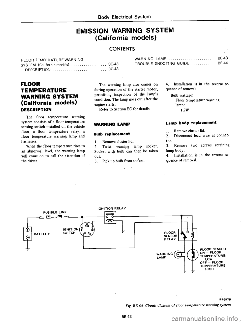
DESCRIPTION
The
floor
temperature
warning
system
consists
of
a
floor
temperature
sensing
switch
installed
on
the
vehicle
floor
a
floor
temperature
relay
a
floor
temperature
warning
lamp
and
harnesses
When
the
floor
temperature
rises
to
an
abnormal
level
the
warning
lamp
will
come
on
to
call
the
attention
of
the
driver
i
f
FUSIBLE
LINK
P
BATTERY
IGNITION
SWITCH
BE
43
8E
43
WARNING
LAMP
TROUBLE
SHOOTING
GUIDE
BE
43
BE
44
The
warning
lamp
also
comes
on
during
operation
of
the
starter
motor
permitting
inspection
of
the
lamp
s
condition
The
lamp
goes
out
after
the
engine
starts
Refer
to
Section
EC
for
details
WARNING
LAMP
Bulb
replacement
I
Remove
cluster
lid
2
Twist
warni
ng
lamp
socket
Socket
with
bulb
can
then
be
taken
out
3
Pick
up
bulb
from
socket
IGNITION
RELAY
I
I
4
Installation
is
in
the
reverse
se
quence
of
removaL
Bulb
wattage
Floor
temperature
warning
lamp
17W
Lamp
body
replacement
I
Remove
cluster
lld
2
Disconnect
lead
wire
at
connee
tor
3
Remove
two
screws
retaining
lamp
body
4
Installation
is
in
the
reverse
se
quence
of
removal
FLOOR
I
l
I
SENSOR
RELAY
WARNING
I
LAMP
FLOOR
SENSOR
ON
FLOOR
TEMPERATURE
LOW
OFF
FLOOR
TEMPERATURE
HIGH
7
BE697B
Fig
BE
64
Circuit
diagram
of
floor
temperature
warning
system
BE
43
Page 489 of 537
Body
Electrical
System
TROUBLE
SHOOTING
GUIDE
Condition
Warning
lamp
does
not
light
in
START
posi
tion
of
ignition
switch
Probable
cause
Burnt
or
loose
bulb
Faulty
f1o
r
temperature
relay
Loose
connection
or
open
circuit
BE
44
Corrective
action
Replace
bulb
or
correct
bulb
socket
Conduct
continuity
test
and
repair
or
reo
place
Refer
to
Section
EC
Check
wiring
and
or
repair
if
necessary