1977 DATSUN PICK-UP high
[x] Cancel search: highPage 71 of 537

30
Install
heatshieid
plate
on
mani
fold
assembly
31
Install
air
gallery
pipe
on
ex
haust
manifold
32
Install
manifold
gasket
and
manifold
assembly
on
cylinder
head
Tightening
torque
1
2to
1
6kg
m
8
7
to
11
6
ft
lb
33
Install
blow
by
gas
pipe
on
cyl
inder
block
and
tighten
with
rear
engine
slinger
34
Install
thermostat
housing
gas
ket
thermostat
housing
and
thermo
stat
35
Install
thermal
vacuum
valve
on
thermostat
housing
Before
installing
apply
a
liquid
packing
slightly
to
the
threads
36
Install
FJ
C
D
bracket
on
cylin
der
head
37
Install
E
G
R
passage
and
E
G
R
valve
on
intake
manifold
38
Connect
E
G
R
tube
to
E
G
R
tube
and
exhaust
manifold
39
Install
check
valve
on
air
gallery
pipe
40
Install
air
cleaner
bracket
on
intake
manifold
41
Install
air
control
valve
on
air
cleaner
bracket
California
models
42
Install
vacuum
and
fuel
tubes
combined
on
cylinder
head
43
Install
distributor
assembly
44
Install
heatshield
plate
joint
seat
and
carburetor
Carbure10r
tightening
torque
0
5
to
1
0
kg
m
3
6
to
7
2
ft
lb
Note
When
instalUng
joint
seat
be
sure
to
put
the
duct
into
primary
hole
in
intake
manifold
S
J
Heatshield
plate
4
Joint
seat
2
Primary
hole
5
Secondary
hole
3
Duct
EM534
Fig
EM
I06
Installing
carburetor
joint
seat
Engine
Mechanical
45
Install
dash
pot
bracket
and
dash
pot
to
intake
manifold
46
Connect
all
air
vacuum
and
fuel
hoses
and
then
secure
with
clamps
I
Cylinder
block
to
P
C
V
valve
hose
2
A
B
valve
to
E
G
R
passage
vac
uum
hose
3
A
B
valve
to
E
G
R
passage
air
hose
4
Vacuum
tube
to
carburetor
vac
uum
hoses
5
Fuel
ube
to
carburetor
fuel
hose
6
Fuel
tube
to
fuel
pump
fuelhose
7
Distributor
to
vacuum
switch
or
spark
delay
valve
vacuum
hose
8
Air
control
valve
vacuum
hose
9
Check
valve
to
air
control
valve
hose
10
Thermal
vacuum
valve
to
E
G
R
valve
vacuum
hose
I
I
Thermal
vacuum
valve
to
vacuum
tube
hose
47
Install
carburetor
air
cleaner
on
carburetor
and
then
connect
air
and
vacuum
hoses
as
follows
I
Air
cleaner
to
exhaust
manifold
hot
air
duct
2
Air
c1eaner
to
air
pump
hose
3
Air
cleaner
to
rocker
cover
hose
4
Air
cleaner
to
air
control
valve
hose
5
6
48
Install
spark
plugs
in
place
49
Connect
all
distributor
high
ten
sion
cables
to
spark
plugs
50
Install
air
pump
drive
belt
cool
er
compressor
and
idler
pulley
51
Install
left
engine
mounting
bracket
52
Install
clutch
assembly
on
flywheel
with
Clutch
Aligning
Bar
KV30100200
Air
cleaner
to
A
B
valve
hose
Other
vacuum
hoses
Tightening
torque
1
2
to
2
2
kg
m
8
7
to
15
9
ft
lb
EM
26
I
I
KV30100200
EM440
Fig
EM
I07
In
talling
clutch
embly
53
Using
an
overhead
hoist
and
lifting
cable
hoist
engine
away
from
engine
stand
and
then
down
onto
engine
carrier
54
Install
right
engine
mounting
bracket
oil
filter
oil
pressure
switch
oil
level
gauge
and
water
drain
plug
When
installing
oil
filter
fasten
it
to
cylinder
block
by
hand
Note
Do
not
overtighten
flit
or
oil
leakage
may
occur
55
Install
alternator
bracket
adjust
ing
bar
alternator
cooling
fan
and
belt
56
Adjust
the
deflection
of
drive
belts
when
thumb
pressure
is
applied
midway
between
pulleys
A
pressed
force
is
above
10
kg
22
0
lb
Deflection
of
drive
belts
8
to
12
mm
0
315
to
0
472
in
EM613
Fig
EM
lOB
Fan
belt
tension
57
Fill
engine
oil
up
to
specified
level
Page 91 of 537
DESCRIPTION
COOLANT
LEVEL
DRAINING
AND
FLUSHING
THE
COOLING
SYSTEM
WATER
PUMP
REMOVAL
AND
INSTALLATION
DISASSEMBLY
INSPECTION
AND
ADJUSTMENT
TORQUE
COUPLING
REMOVAL
AND
INSTALLATION
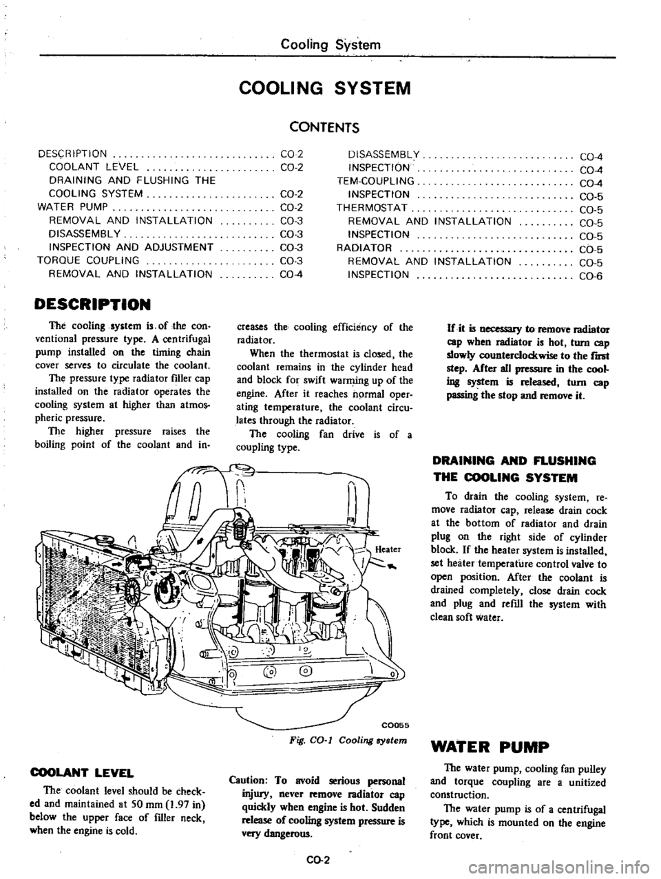
DESCRIPTION
The
cooling
system
is
of
the
con
ventional
pressure
type
A
centrifugal
pump
installed
on
the
timing
chain
cover
serves
to
circulate
the
coolant
The
pressure
type
radiator
filler
cap
installed
on
the
radiator
operates
the
cooling
system
at
higher
than
atmos
pheric
pressure
The
higher
pressure
raises
the
boiling
point
of
the
coolant
and
in
Cooling
System
COOLING
SYSTEM
CONTENTS
CO
2
CO
2
OISASSEMBL
Y
INSPECTION
TEM
COUPLlNG
INSPECTION
THERMOSTAT
REMOVAL
AND
INSTALLATION
INSPECTION
RADIATOR
REMOVAL
AND
INSTALLATION
INSPECTION
CO
2
CO
2
CO
3
CO
3
CO
3
CO
3
CO
4
creases
the
cooling
efficiency
of
the
radiator
When
the
thermostat
is
closed
the
coolant
remains
in
the
cylinder
head
and
block
for
swift
warming
up
of
the
engine
After
it
reaches
normal
oper
ating
temperature
the
coolant
circu
lates
through
the
radiator
The
cooling
fan
drive
is
of
a
coupling
type
COOLANT
LEVEL
The
coolant
level
should
be
check
ed
and
maintained
at
SO
mm
1
97
in
below
the
upper
face
of
filler
neck
when
the
engine
is
cold
C0055
Fig
CO
I
Cooling
ry
lem
Caution
To
avoid
serious
personal
injury
never
remove
I3diator
cap
quickly
when
engine
is
hot
Sudden
release
of
cooling
system
pressure
is
very
dangerous
CO
2
CO
4
CO
4
CO
4
CO
5
CO
5
CO
5
CO
5
CO
5
CO
5
CO
6
If
it
is
necessary
to
remove
radiator
cap
wben
radiator
is
hot
turn
cap
slowly
counterclockwise
to
the
r
step
After
all
pressure
in
the
cool
ing
system
is
released
tom
cap
passing
the
stop
and
remove
it
DRAINING
AND
FLUSHING
THE
COOLING
SYSTEM
To
drain
the
cooling
system
re
move
radiator
cap
release
drain
cock
at
the
bottom
of
radiator
and
drain
plug
on
the
right
side
of
cylinder
block
If
the
heater
system
is
installed
set
heater
temperature
control
valve
to
open
position
After
the
coolant
is
drained
completely
close
drain
cock
and
plug
and
refill
the
system
with
clean
soft
water
WATER
PUMP
The
water
pump
cooling
fan
pulley
and
torque
coupling
are
a
unitized
construction
The
water
pump
is
of
a
centrifugal
type
which
is
mounted
on
the
engine
front
cover
Page 92 of 537
The
pump
shaft
is
supported
by
a
double
row
of
ball
bearings
press
fit
in
an
aluminum
die
cast
pump
body
The
bearings
are
permanently
lubricated
and
sealed
to
prevent
loss
of
lubricant
and
entry
of
dirt
The
pump
is
provided
with
an
impeller
which
turns
on
a
steel
shaft
The
steel
shaft
rotates
together
with
the
torque
coupling
wheeL
The
volute
chamber
is
built
in
the
engine
front
cover
assembly
The
inlet
of
the
pump
is
connected
to
the
radiator
s
lower
tank
by
a
hose
i
o
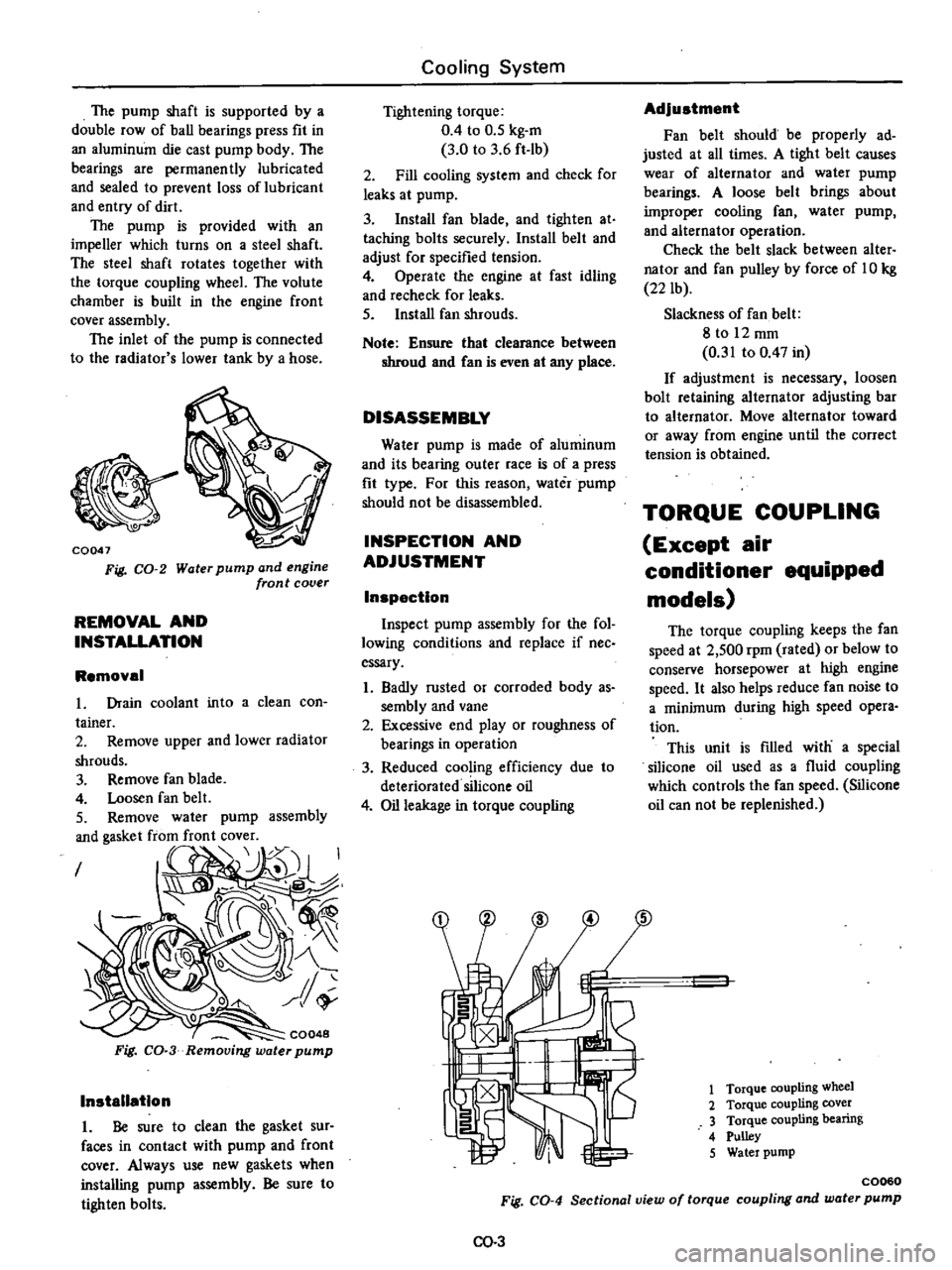
CQ047
Fig
CO
2
Water
pump
and
engine
front
cover
REMOVAL
AND
INSTALLATION
Removal
in
to
a
clean
con
assembly
I
CQ048
Fig
CO
3
Removing
water
pump
Installation
1
Be
sure
to
clean
the
gasket
sur
faces
in
contact
with
pump
and
front
cover
Always
use
new
gaskets
when
installing
pump
assembly
Be
sure
to
tighten
bolts
Cooling
System
Tightening
torque
0
4
to
0
5
kg
m
3
0
to
3
6
ft
lb
2
Fill
cooling
system
and
check
for
leaks
at
pump
3
Install
fan
blade
and
tighten
at
taching
bolts
securely
Install
belt
and
adjust
for
specified
tension
4
Operate
the
engine
at
fast
idling
and
recheck
for
leaks
5
Install
fan
shrouds
Note
Ensure
that
clearance
between
shroud
and
Can
is
even
at
any
place
DISASSEMBLY
Water
pump
is
made
of
aluminum
and
its
bearing
outer
race
is
of
a
press
fit
type
For
this
reason
water
pump
should
not
be
disassembled
INSPECTION
AND
ADJUSTMENT
Inspection
Inspect
pump
assembly
for
the
fol
lowing
conditions
and
replace
if
nee
essary
1
Badly
rusted
or
corroded
body
as
sembly
and
vane
2
Excessive
end
play
or
roughness
of
bearings
in
operation
3
Reduced
cooling
efficiency
due
to
deteriorated
silicone
oil
4
Oil
leakage
in
torque
coupling
Adjustment
Fan
belt
should
be
properly
ad
justed
at
all
times
A
tight
belt
causes
wear
of
alternator
and
water
pump
bearings
A
loose
belt
brings
about
improper
cooling
fan
water
pump
and
alternator
operation
Check
the
belt
slack
between
alter
nator
and
fan
pulley
by
force
of
10
kg
22
lb
Slackness
of
fan
belt
8
to
12
mm
0
31
to
0
47
in
If
adjustment
is
necessary
loosen
bolt
retaining
alternator
adjusting
bar
to
alternator
Move
alternator
toward
or
away
from
engine
until
the
correct
tension
is
obtained
TORQUE
COUPLING
Except
air
conditioner
equipped
models
The
torque
coupling
keeps
the
fan
speed
at
2
500
rpm
rated
or
below
to
conserve
horsepower
at
high
engine
speed
It
also
helps
reduce
fan
noise
to
a
minimum
during
high
speed
opera
tion
This
unit
is
filled
with
a
special
silicone
oil
used
as
a
fluid
coupling
which
controls
the
fan
speed
Silicone
oil
can
not
be
replenished
1
Torque
coupling
wheel
2
Torque
coupling
cover
3
Torque
coupling
bearing
4
Pulley
5
Water
pump
C0060
Fig
CO
4
Sectional
view
of
torque
coupling
and
water
pump
00
3
Page 93 of 537

REMOVAL
AND
INSTALLATION
To
replace
the
torque
coupling
follow
the
same
procedure
as
in
the
water
pump
The
torque
coupling
can
not
be
separated
from
the
water
pump
Cooling
System
DISASSEMBLY
The
torque
coupling
is
so
designed
that
it
can
not
be
disassembled
INSPECTION
Inspect
torque
coupling
for
oil
leakage
If
necessary
replace
TEM
COUPLl
G
For
air
conditioner
equipped
models
Tem
coupling
is
a
type
of
fan
coupling
which
is
provided
with
a
temperature
control
system
The
conventional
coupling
always
slips
the
fan
at
a
high
speed
under
a
constant
ratio
regardless
of
the
engine
cooling
requirement
The
slipping
ratio
of
the
Tern
coupling
however
is
properly
changed
with
the
cooling
requirement
ON
denotes
that
cooling
is
re
quired
and
the
fan
operates
up
to
about
2
150
rpm
When
high
cooling
is
not
required
during
cold
season
with
the
engine
warmed
up
etc
the
oper
w
6
I
1
Bi
metal
thermostat
2
Slide
valve
3
Reserve
chamber
for
OFF
4
Bearing
5
Driving
chamber
for
ON
6
ouplingpart
labyrinth
coon
Fig
CO
5
CrQM
sectional
view
of
Tem
coupling
ation
is
placed
under
OFF
condition
and
the
fan
slips
at
about
1
650
rpm
The
coiled
bimetal
thermostat
installed
on
the
front
center
portion
of
the
Tem
coupling
detects
temperature
of
air
passing
through
the
radiator
The
air
temperature
is
directly
relative
to
the
engine
coolant
tempera
ture
and
the
inside
slide
valve
is
opened
or
closed
as
required
and
thus
the
ON
OFF
control
is
performed
When
the
air
temperature
rises
the
bimetal
is
expanded
and
the
valve
is
opened
silicon
oil
is
forwarded
to
the
groove
that
transmits
torque
and
the
CO
4
system
is
placed
under
ON
con
dition
When
the
valve
closes
silicone
oil
is
not
supplied
to
the
driving
chamber
oil
in
the
driving
chamber
is
accumu
lated
on
periphery
due
to
the
centrif
ugal
force
and
led
into
the
reserve
chamber
Now
oil
is
eliminated
from
the
driving
chamber
and
the
system
is
placed
under
OFF
condition
With
this
system
when
fan
cooling
is
not
required
the
output
loss
is
minimized
and
noise
can
be
far
reduced
Page 100 of 537

Underhood
air
I
@
Dr
Underhood
air
I
Engine
Fuel
f
f
l
l
ID
s
6
Cif
Ittl
ID
Air
inlet
pipe
Air
con
trol
valve
Hot
air
pipe
Diaphragm
Vacuum
hose
Diaphragm
spring
Air
bleed
valve
closed
Temperature
sensor
assembly
Holair
EF114
Fig
EF
2
Hota
r
delivery
mode
During
cold
engine
operation
7
To
manifold
Small
vacuum
1
Air
inlet
pipe
2
Air
con
trol
valw
3
Hot
air
pipe
4
Diaphnp
S
V
leuum
hoses
6
Diaphragm
prinl
7
Air
bleed
valve
closed
II
Temperature
senSOr
assembly
EF20S
Fig
EF
3
Cold
air
delivery
mode
During
cold
engine
operation
f
1
J
liP
omanifold
2
@
Air
inlet
pipe
Air
control
valve
Hot
air
pipe
Diaphragm
Vacuum
hoses
Diaphragm
spring
Air
bleed
valve
fully
open
8
Temperature
sensor
assembly
EF715
Fig
EF
4
Cold
air
delivery
mode
During
hot
engine
operation
ID
@
f
fjr
R
lfl
ow
2
underh
r
5
rv
Itti
ID
Hot
air
Air
inlet
pipe
Air
control
valve
Hot
air
pipe
Diaphragm
Vacuum
hose
Diaphragm
spring
Air
bleed
valve
partially
opened
8
Temperature
sensor
assembly
EF716
Fig
EF
5
Regulating
air
delivery
mode
EF
4
A
T
C
AIR
CLEANER
COLD
AIR
OPERATION
I
When
under
hood
air
temperature
is
low
The
sensor
air
bleed
valve
remains
in
the
closed
position
and
vacuum
passage
is
established
between
the
in
take
manifold
and
the
vacuum
motor
and
the
intake
manifold
vacuum
is
applied
to
the
vacuum
motor
dia
phragm
When
the
vacuum
is
small
or
when
the
engine
is
operating
under
eavy
1004
the
air
control
valve
opens
widely
irrespective
of
the
temperature
around
the
sensor
to
introduce
the
under
hood
air
cold
air
for
increased
power
of
the
engine
2
When
under
hood
air
temperature
is
high
The
sensor
air
bleed
valve
opens
fully
to
shut
off
the
vacuum
passage
between
the
intake
manifold
and
the
vacuum
motor
Due
to
the
force
of
the
vacuum
motor
diaphragm
spring
the
air
control
valve
closes
the
hot
air
pipe
of
the
air
cleaner
and
introduces
the
under
hood
air
cold
air
A
T
C
AIR
CLEANER
COLD
AND
HOT
AIR
OPERATION
When
the
sensor
air
bleed
valve
is
partially
opened
opening
of
the
air
control
valve
varies
with
the
vacuum
of
the
intake
manifold
With
the
air
control
valve
half
open
the
cold
air
and
hot
air
are
sucked
together
and
mixed
for
controlling
of
the
air
tem
perature
of
the
air
to
be
introduced
to
the
air
cleaner
Page 103 of 537

to
facilitate
smooth
operation
of
air
control
valve
If
the
above
test
reveals
any
prob
lem
in
the
operation
of
air
control
valve
carry
out
the
following
test
4
Remove
air
cleaner
cover
Set
temperature
sensing
element
of
ther
mistor
or
thermometer
to
a
position
where
temperature
around
sensor
can
be
measured
In
this
case
fIx
wiring
of
thermistor
or
thermometer
on
the
bottom
surface
of
air
cleaner
with
adhesive
tape
in
such
a
manner
that
the
set
position
of
temperature
sensing
DESCRIPTION
OPERATION
DESCRIPTION
The
idle
compensator
is
basically
a
thermostatic
valve
which
functions
to
introduce
the
air
directly
from
the
air
cleaner
to
the
intake
manifold
to
compensate
for
abnormal
enrichment
of
mixture
in
high
idle
temperature
The
bi
metal
attached
to
the
idle
compensator
detects
the
temperature
of
intake
air
and
opens
or
closes
the
valve
Two
idle
compensators
having
different
temperature
characteristics
are
installed
one
opens
at
an
intake
air
temperature
of
60
to
700C
140
to
l580F
and
the
other
at
70
to
900C
158
to
1940F
OPERATION
The
construction
of
the
idle
com
pensator
is
shown
in
the
following
Engine
Fuel
element
will
not
be
affected
by
air
flow
Then
install
air
cleaner
cover
Fig
EF
13
Checking
temperature
sensor
IDLE
COMPENSATOR
CONTENTS
5
Carry
out
test
as
described
in
steps
I
2
and
3
above
When
air
control
valve
begins
to
open
to
under
hood
air
inlet
side
several
minutes
after
engine
starting
read
the
indica
tion
of
thermistor
or
thermometer
If
reading
falls
within
the
working
tern
perature
range
of
temperature
sensor
the
sensor
is
normal
If
reading
ex
ceeds
the
range
replace
the
sensor
with
new
one
Note
Before
replacing
temperature
sensor
check
idle
compensator
as
described
in
Idle
compensator
EF
7
EF
7
REMOVAL
AND
INSTALLATION
INSPECTION
EF
B
EF
8
q
EF222
1
Orifice
2
Bi
metal
3
Rubber
valve
Fig
EF
14
Structure
of
idle
compensator
Bi
metal
Intake
air
temperature
No
1
Below
600C
1400F
60
to
70
C
140
to
l580F
Above
700C
158
OF
Below
700C
1580F
70
to
900C
158
to
1940F
Above
900C
1940F
No
2
EF
7
The
idle
compensator
operates
in
response
to
the
under
hood
air
temper
ature
as
shown
below
Idle
compensator
operation
Fully
closed
Close
to
open
Fully
open
Fully
closed
Close
to
open
Fully
open
Page 107 of 537

3
Check
diaphragm
for
small
holes
carcks
or
wear
4
Check
rocker
arm
for
wear
at
the
mating
portion
with
camshaft
5
Check
rocker
arm
pin
for
wear
A
worn
pin
may
cause
oil
leakage
6
Check
all
other
components
for
any
abnormalities
and
replace
if
neces
sary
DESCRIPTION
INSPECTION
REMOVAL
AND
INSTALLATION
DESCRIPTION
The
electric
fuel
pump
is
adopted
on
air
conditioner
equipped
models
Engine
Fuel
ASSEMBLY
Reverse
the
order
of
disassembly
Closely
observe
the
following
instruc
tions
L
Use
new
gaskets
2
Lubricate
rocker
ann
rocker
arm
link
and
rocker
arm
pin
before
installa
tion
3
To
test
the
function
proceed
as
follows
Position
fuel
pump
assembly
about
I
meter
3
3
ft
above
fuel
level
of
fuel
strainer
and
connect
a
pipe
from
strainer
to
fuel
pump
Operate
rocker
arm
by
hand
If
fuel
is
drawn
up
soon
after
rocker
arm
is
released
fuel
pump
is
functioning
properly
ELECTRIC
FUEL
PUMP
CONTENTS
EF
11
EF
11
EF
12
DISASSEMBL
Y
ASSEMBL
Y
TROUBLE
DIAGNOSES
AND
CORRECTIONS
EF
12
EF
12
The
silicon
transistor
type
fuel
pump
consists
of
a
transistor
diodes
a
sole
I
Tr
lOsistor
6
Ou
tIet
valve
2
Plunger
7
Return
spring
3
Diaphragm
8
Filter
4
Diode
9
Magnet
5
Magnet
coil
10
Inlet
valve
INSPECTION
I
Disconnect
fuel
hose
at
pump
outlet
2
Connect
a
suitable
hose
approxi
mately
6
mm
0
24
in
inner
dia
meter
to
pump
outlet
ev
J
J
Note
If
diameter
is
too
small
the
following
proper
delivery
capacity
cannot
be
obtained
even
if
pump
functions
properly
EF
11
EF
13
noid
a
pump
mechanism
and
filter
parts
I
T
nsistor
2
Re
ist
f
I
3
Dinde
4
Signal
coil
5
Main
coil
6
Resistor
3
7
Zener
dlOdl
8
Resistor
2
EF719
Fig
EF
22
Construction
of
electric
fuel
pump
3
With
hose
outlet
in
a
higher
posi
tion
than
pump
operate
pump
and
check
delivery
capacity
for
more
than
15
seconds
4
The
capacity
should
be
I
400
cc
Page 109 of 537

Engine
Fuel
TROUBLE
DIAGNOSES
AND
CORRECTIONS
Condition
Fuel
pump
fails
to
operate
Fuel
pump
fails
to
discharge
sufficient
flow
Insufficient
fuel
discharge
during
high
speed
travelling
Low
float
level
at
idling
Fuel
pump
is
actuated
more
frequently
than
under
normal
condi
tion
Rattling
noise
Probable
cause
Terminals
or
connections
loose
Rust
on
terminals
or
grounding
metal
Frozen
liquid
in
plunger
or
pump
Clogged
filter
Insufficient
fuel
Air
in
fuel
hose
through
connections
Hose
necked
down
or
bent
Fuel
tank
breather
tube
bent
or
necked
down
Weakened
return
spring
Air
sucked
through
connection
fuel
hose
and
fuel
pump
joint
Fuel
hose
on
suction
side
bent
Clogged
fIlter
Mounting
bolts
loose
EF
13
Corrective
action
Retighten
Clean
Clean
plunger
assembly
Replace
pump
if
plunger
is
stuck
or
seized
Clean
pump
interior
Clean
and
if
necessary
replace
fIlter
Replenish
Apply
a
coating
of
end
sealing
compound
to
connections
and
retighten
Check
and
correct
Check
and
correct
Replace
Apply
a
coating
of
end
sealing
compound
to
connection
and
retighten
Check
and
correct
Clean
or
replace
fIlter
Retighten