1977 DATSUN PICK-UP steering
[x] Cancel search: steeringPage 364 of 537

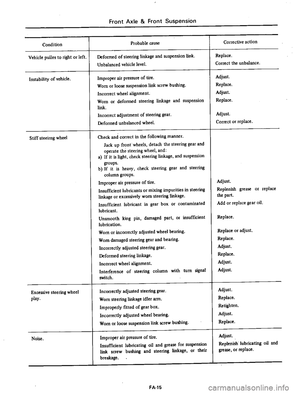
Condition
Vehicle
puBes
to
right
or
left
Instability
of
vehicle
Stiff
steeirng
wheel
Excessive
steering
wheel
play
Noise
Front
Axle
Front
Suspension
Probable
cause
Deformed
of
steering
linkage
and
suspension
link
Unbalanced
vehicle
level
Improper
air
pressure
of
tire
Worn
or
loose
suspension
link
screw
bushing
Incorrect
wheel
alignment
Worn
or
deformed
steering
linkage
and
suspension
link
Incorrect
adjustment
of
steering
gear
Deformed
unbalanced
wheel
Check
and
correct
in
the
following
manner
Jack
up
front
wheels
detach
the
steering
gear
and
operate
the
steering
wheel
and
a
If
it
is
light
check
steering
linkage
and
suspension
groups
b
If
it
is
heavy
check
steering
gear
and
steering
column
groups
Improper
air
pressure
of
tire
Insufficient
lubricants
or
mixing
impurities
in
steering
linkage
or
excessively
worn
steering
linkage
Insufficient
lubricant
in
gear
box
or
contaminated
lubricant
Unsmooth
king
pin
damaged
part
Or
insufficient
lubrication
Worn
or
incorrectly
adjusted
wheel
bearing
Worn
damaged
steering
gear
and
bearing
Incorrectly
adjusted
steering
gear
Deformed
steering
linkage
Incorrect
wheel
alignment
Interference
of
steering
column
with
turn
signal
switch
Incorrectly
adjusted
steering
gear
Worn
steering
linkage
idler
arm
Improperly
fitted
of
gear
box
Incorrectly
adjusted
wheel
bearing
Worn
or
loose
suspension
link
screw
bushing
Improper
air
pressure
of
tire
Insufficient
lubricating
oil
and
grease
for
suspension
link
screw
bushing
and
steering
linkage
or
their
breakage
FA
15
Corrective
action
Replace
Correct
the
unbalance
Adjust
Replace
Adjust
Replace
Adjust
Correct
or
replace
Adjust
Replenish
grease
or
replace
the
part
Add
or
replace
gear
oil
Replace
Replace
or
adjust
Replace
Adjust
Replace
Adjust
Adjust
Adjust
Replace
Retighten
Adjust
Replace
Adjust
Replenish
lubricating
oil
and
grease
or
replace
Page 365 of 537

Condition
Noise
Grating
tire
noise
Jumping
of
disc
wheeL
Excessively
or
partially
worn
tire
Front
Axle
Front
Suspension
Probable
cause
Loose
steering
gear
bolts
linkage
and
suspension
groups
Faulty
shock
absorber
Damaged
wheel
bearing
Worn
steering
linkage
and
steering
gear
Worn
of
loose
suspension
link
screw
bushing
Improper
air
pressure
of
lire
Incorrect
wheel
alignment
Deformed
knuckle
spindle
and
suspension
linkage
Rough
driving
Improper
air
pressure
of
tire
Unbalanced
wheels
Faulty
shock
absorber
Worn
tire
Deformed
wheel
rim
Improper
air
pressure
of
tire
Incorrect
wheel
alignment
Damaged
wheel
bearing
Incorrect
brake
adjustment
Improper
tire
shifting
rotation
Rough
and
improper
wiving
manner
FA
16
Corrective
action
Retighten
Replace
Replace
Replace
Replace
Adjust
Adjust
Replace
Avoid
rough
driving
Adjust
Adjust
Replace
Replace
Replace
Adjust
Adjust
Replace
Adjust
Adjust
Drive
more
gently
Page 383 of 537

REMOVAL
1
Removing
flare
nuts
on
both
ends
and
clips
effects
the
removal
of
brake
tube
and
brake
hose
2
Rear
brake
hose
can
be
removed
by
disconnecting
the
tube
and
then
turning
round
the
hose
Note
When
removing
brake
tubes
and
hoses
use
Flare
Nut
Torque
Wrench
GG943IOOOO
Never
use
an
OpeD
end
or
an
adjust
able
wrench
INSPECTION
1
Examine
all
hoses
for
swell
rubbing
marks
or
ozone
cracking
re
placing
those
found
with
any
of
above
badly
beyond
use
Also
inspect
end
fittings
and
be
sure
that
no
fluid
leak
through
staked
end
has
taken
place
replace
if
necessary
Hose
with
badly
rusted
fitting
should
also
be
replaced
with
a
new
one
2
Clean
all
tubes
to
remove
dust
and
dirt
with
isopropyl
alcohol
check
ing
for
collapse
wear
cracking
swell
or
rusting
Replace
if
foun
d
with
any
of
wove
Use
care
not
to
damage
brake
tubes
while
operation
Check
if
tubes
are
clamped
secure
ly
Mter
all
brake
lines
have
been
installed
retighten
aU
connections
if
necessary
to
assist
in
obtaining
correct
torque
In
retightening
at
front
wheel
cylinder
first
remove
hose
clamp
and
loosen
flare
nut
on
opposite
side
to
avoid
twisting
hose
Hold
pedal
as
far
downward
as
possible
80
kg
176
lb
or
more
examining
evidence
as
to
whether
fluid
is
leaking
through
brake
lines
or
con
nections
Leakage
in
any
manner
can
not
be
permitted
here
In
case
fluid
leaks
tightening
to
specified
torque
tighten
additionally
up
to
2
5
kg
m
J
8
ft
lb
Under
no
circumstances
should
not
be
tightened
over
2
5
kg
m
18
ft
Ib
torque
since
this
elongates
end
fitting
making
it
impossible
to
reuse
brake
tube
Under
no
circumstances
should
rear
brake
hose
and
3
way
connector
be
retightened
over
specified
torques
In
Brake
System
stead
replace
copper
washer
with
a
new
one
after
checking
for
sign
of
damage
on
seating
surface
Never
reuse
an
old
copper
washer
INSTALLATION
Brake
hose
Front
brake
hose
In
installing
brake
hose
first
jack
up
vehicle
to
take
off
the
weight
of
vehicle
from
wheels
so
that
suspension
is
in
rebound
Steering
wheel
should
also
be
kept
in
straight
ahead
position
To
connect
brake
line
first
connect
brake
hose
to
wheel
cylinder
with
the
specified
torque
Tightening
torque
1
7
to
2
0
kg
m
12
to
14
ft
Ib
Then
secure
brake
hose
to
the
bracket
with
lock
plate
so
as
not
to
twist
or
abnormally
bend
the
hose
Note
After
connecting
brake
hose
at
both
eiuIs
pay
keen
attention
not
to
twist
the
hose
when
additional
tightening
is
required
Fig
BR
12
Front
brake
hose
Rear
brake
hose
First
secure
rear
brake
hose
to
3
way
connector
on
rear
axle
case
to
the
specifications
Mter
connecting
hose
do
not
tighten
it
at
3
way
connector
additionally
since
this
oper
ation
causes
hose
to
be
twisted
Tightening
torque
I
7
to
2
0
kg
m
12
to
14
ft
Ib
BR
8
Fig
BR
13
Rear
brake
ho
e
After
brake
hose
has
been
installed
check
to
be
sure
that
there
is
enough
clearance
between
hose
and
adjacent
parts
to
avoid
contact
with
other
ones
The
check
should
be
carried
out
while
moving
wheel
up
and
down
through
its
full
stroke
and
rotating
steering
wheel
between
two
extreme
lock
positions
The
wow
clearance
must
be
as
follows
Hose
to
rotating
or
mOving
parts
such
as
tire
and
rim
40
mm
1
57
in
and
more
Hose
to
stationary
part
2S
mm
0
98
in
and
more
In
case
that
the
above
clearance
cannot
be
obtained
it
may
be
caused
by
the
hose
twisted
Accordingly
carry
out
the
correction
with
hose
connection
again
following
the
above
instructions
Brake
tube
In
installing
a
brake
tube
use
care
to
locate
its
end
squarely
on
mating
seat
noting
the
fact
that
nut
can
be
turned
freely
by
a
light
finger
twist
Then
tighten
to
correct
torque
with
a
Brake
Pipe
Torque
Wrench
GG943
10000
Tightening
torque
Flare
nut
1
5
to
1
8
kg
m
11
to
13
ft
Ib
In
addition
care
should
also
be
exercised
to
avoid
damaging
or
col
lapsing
brake
tube
during
operation
Be
sure
to
make
enough
clearance
between
all
tubes
and
other
adjacent
parts
to
avoid
contact
In
installing
tube
through
hood
ledge
grommet
be
sure
to
position
it
at
the
center
of
grommet
Page 402 of 537

DESCRIPTION
MAINTENANCE
AND
SERVICE
TIRE
INFLATION
TIRE
REPAIR
WHEEL
REPAIR
WEAR
DESCRIPTION
The
620
series
models
are
equipped
with
4lV
14
wheels
with
25
mOl
0
98
in
offset
All
tires
are
tubeless
Wheel
and
Tire
WHEEL
AND
TIRE
CONTENTS
WT2
WT
2
WT2
WT2
WT
2
WT
2
TIRE
ROTATION
CHANGING
TIRE
INSPECTION
WHEEL
BALANCE
WHEEL
AND
TIRE
Tire
size
Model
Tire
size
Wheel
size
All
models
6
00
I
4
6PR
Tubeless
4UJ
14
Tire
pressure
Unit
kgl
em
2
psi
Vehicle
speed
km
h
MPH
Under
Over
100
km
h
100
km
h
Model
60
MPH
60
MPH
Front
1
5
21
1
8
26
Unloaded
Rear
175
25
2
25
32
All
models
Front
1
5
21
1
8
26
Loaded
Rear
3
0
42
3
15
4S
Note
Tire
inflation
pressures
should
be
measured
when
tires
are
cold
MAINTENANCE
AND
SERVICE
TIRE
INFLATION
Correct
tire
pressure
is
very
im
portant
to
ease
of
steering
and
riding
comfort
This
also
reduces
driving
sound
to
a
minimum
resulting
in
longer
tire
life
that
is
overinflation
or
underinflation
promotes
wear
at
cen
ter
tread
or
shouider
of
tire
If
aU
tires
are
inspected
frequently
and
maintained
correct
tire
pressure
it
is
possible
to
detect
sharp
material
in
the
tread
Also
the
above
check
avoids
abnormal
wear
which
invites
serious
problem
If
tires
indicate
abnormal
or
uneven
wear
the
cause
of
problem
should
be
detected
and
eliminated
After
inflating
tires
leakage
in
valve
should
be
checked
Without
valve
caps
leakage
will
occur
due
to
dirt
and
water
resulting
in
underinflation
Ac
cordingly
whenever
tire
pressure
is
checked
be
sure
to
tighten
valve
caps
firmly
by
hand
WT
2
WT3
WT3
WTA
WTA
WT
4
TIRE
REPAIR
In
order
to
inspect
a
leak
apply
soapy
solution
to
tire
or
submerge
tire
and
wheei
in
the
water
after
inflating
tire
to
specified
pressure
Special
in
spection
for
leaks
should
be
carried
out
around
the
valve
wheel
rim
and
along
the
tread
Exercise
care
to
bead
and
rim
where
leakage
occurs
Wipe
out
water
from
area
which
leaks
air
bubbles
and
then
mark
the
place
with
chalk
After
removing
the
materials
which
caused
puncture
seal
the
point
When
repairing
the
puncture
use
the
tire
repair
kits
which
are
furnished
from
tire
dealers
following
the
instructions
provided
with
the
kits
In
case
that
a
puncture
becomes
large
or
there
is
any
other
damage
on
the
tire
fabric
repair
must
be
carried
out
by
authorized
tire
dealers
WHEEL
REPAIR
Inspect
the
wheel
rim
flange
for
bend
or
dents
The
flange
should
be
cleaned
by
a
wire
brush
when
rust
is
found
on
the
flange
Furthermore
if
excessive
pitting
occurs
on
the
rim
eliminate
it
with
a
file
WEAR
Missilgnment
When
the
front
wheels
align
in
excessive
toe
in
or
toe
out
condition
tires
scrape
the
tread
rubber
off
The
wear
of
tread
appears
feathered
edge
Page 404 of 537

4
To
jack
up
rear
place
jack
under
rear
axle
case
close
to
the
side
of
rear
spring
after
applying
parking
brake
and
blocking
front
wheels
WH077
Fig
WT
7
Jacking
up
rear
side
S
Remove
wheel
nuts
and
wheel
from
drum
6
To
install
wheel
reverse
the
above
steps
Tighten
wheel
nuts
in
criss
cross
fashion
to
8
0
to
9
0
kg
m
S8
to
6S
ft
Ib
Note
Nerer
get
under
the
vehicle
while
it
is
supported
only
by
the
jack
Always
use
S8
fety
stands
to
support
the
side
member
of
body
construction
when
you
must
get
beneath
the
vehicle
INSPECTION
WHEEL
BALANCE
The
wheel
arid
tire
asSembly
should
be
kept
balanced
statically
and
dynam
ically
Wheel
and
Tire
Proper
tire
balance
is
necessary
when
driving
the
vehicle
at
high
speeds
Consequently
the
wheel
and
tire
assembly
should
be
properly
re
balanced
whenever
puncture
is
re
paired
The
wheel
and
tire
assembly
be
comes
out
of
ba1ance
according
to
uneven
tire
wear
Severe
acceleration
and
braking
or
fast
cornering
is
the
cause
of
wear
on
tire
resulting
in
unbalance
of
tire
and
wheel
assembly
The
symptom
of
unbalance
appears
as
tramp
vehicle
shake
and
steering
malfunction
To
correct
unbalance
use
proper
wheel
balancer
Maximum
allowable
unbalance
177
gr
cm
2
5
in
oz
10
gr
O
3S
oz
at
rim
circumferences
Balance
weight
10
to
60
gr
O
3S
to
2
12
oz
at
10
gr
0
3S
oz
intervat
Note
Be
sure
to
place
the
correct
balance
weights
on
the
inner
edge
of
rim
as
shown
in
Figure
WT
S
00
not
put
more
than
two
weights
on
each
side
WHEEL
AND
TIRE
In
order
to
ensure
satisfactory
steering
condition
as
well
as
maximum
tire
life
proceed
as
follows
Check
wheel
rim
for
rust
distor
tion
cracks
or
other
faults
WT
4
Thoroughly
remove
rust
dust
oxidized
rubber
or
sand
from
wheel
rim
with
wire
brush
emery
cloth
or
paper
Use
dial
gauge
to
examine
wheel
rim
for
lateral
run
out
Lateral
run
Qut
limit
Less
tltan
1
5
mOl
0
059
il
total
indicator
reading
WTOO5
Fig
WT
B
Whetl
rim
run
out
check
points
Note
In
replacing
tire
t
e
extra
care
not
to
damage
tire
bead
rim
flange
and
bead
seat
Do
not
use
tire
irons
to
force
beads
away
from
wheel
rim
flange
that
is
always
use
tire
replacement
device
whenever
tire
is
removed
2
Discard
when
any
of
the
follow
ing
problems
occur
1
Broken
or
damaged
bead
wire
2
Ply
o
treairsepanitiori
3
Cracked
or
damaged
side
wall
etc
Page 405 of 537

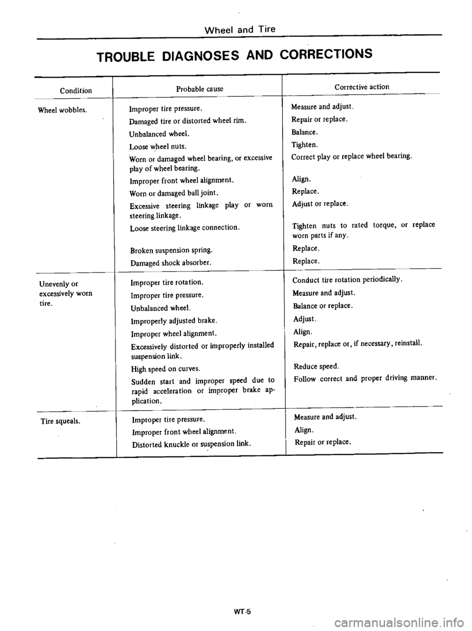
Condition
Wheel
wobbles
Unevenly
or
excessively
worn
tire
Tire
squeals
Wheel
and
Tire
TROUBLE
DIAGNOSES
AND
CORRECTIONS
Probable
cause
Improper
tire
pressure
Damaged
tire
or
distorted
wheel
rim
Unbalanced
wheel
Loose
wheel
nuts
Worn
or
damaged
wheel
bearing
or
excessive
play
of
wheel
bearing
Improper
front
wheel
alignment
Worn
or
damaged
ball
joint
Excessive
steering
linkage
play
or
worn
steering
linkage
Loose
steering
linkage
connection
Broken
suspension
spring
Damaged
shock
absorber
Improper
tire
rotation
Improper
tire
pressure
Unbalanced
wheel
Improperly
adjusted
brake
Improper
wheel
alignment
Excessively
distorted
or
improperly
installed
suspension
link
High
speed
on
curves
Sudden
start
and
improper
speed
due
to
rapid
acceleration
or
improper
brake
ap
plication
Improper
tire
pressure
Improper
front
wheel
alignment
Distorted
knuckle
or
suspension
link
WT
5
Corrective
action
Measure
and
adjust
Repair
or
replace
Balance
Tighten
Correct
play
or
replace
wheel
bearing
Align
Replace
Adjust
Or
replace
Tighten
nuts
to
rated
torque
or
replace
worn
parts
if
any
Replace
Replace
Conduct
tire
rotation
periodically
Measure
and
adjust
Balance
or
replace
Adjust
Align
Repair
replace
or
if
necessary
reinstall
Reduce
speed
Follow
correct
and
proper
driving
manner
Measure
and
adjust
Align
Repair
or
replace
Page 406 of 537

SERVICE
MANUA
L
4
DATSUN
PICK
UP
MODEL
620
SERIES
I
NISSAN
I
NI55AN
MOTOR
CO
LTD
TOKYO
JAPAN
SECTION
ST
STEERING
SYSTEM
STEERING
SERVICE
DATA
AND
SPECIFICATIONS
TROUBLE
DIAGNOSES
AND
CORRECTION
SPECIAL
TOOLS
ST
2
ST
8
ST
9
ST
10
Page 407 of 537

STEERING
SYSTEM
STEERING
CONTENTS
DESCRIPTION
STEERING
GEAR
Remo
al
and
installation
Disassembly
and
assembly
ST
2
ST
3
ST
3
ST
4
Inspection
and
repair
STEERING
LINKAGE
Removal
and
installation
Inspection
and
repair
ST
5
ST
6
ST
6
ST
7
DESCRIPTION
The
other
end
of
the
cross
rod
is
linked
to
the
idler
arm
connecting
with
the
side
member
located
on
the
opposite
side
of
the
steering
gear
The
two
side
rods
serve
to
connect
the
steering
gear
arm
and
idler
arm
to
the
both
knuckle
arms
right
and
left
hand
sides
With
this
construction
even
if
the
left
andlor
right
wheel
moves
vertical
The
steering
gear
used
on
this
model
series
vehicles
is
e
same
re
circulating
type
This
steering
gear
is
designed
especially
for
easy
operation
and
high
durability
The
steering
linkage
is
of
a
relay
design
of
which
gear
arm
is
connected
to
one
end
of
the
adjustable
cross
rod
ly
and
independently
steering
can
be
safely
maintained
Steering
wheel
rotation
is
converted
to
gear
arm
motion
in
proportion
to
the
gear
ratio
by
the
steering
gear
The
gear
arm
motion
operates
the
side
rod
on
the
same
side
At
the
same
time
the
idler
arm
is
moved
through
the
cross
rod
and
the
opposite
side
rod
is
also
moved
1
Steering
column
shaft
2
Steering
column
jacket
3
Steering
wheel
4
Column
clamp
S
Post
gro
llmet
6
Steering
gear
arm
sr
2
7
Cross
rod
8
Cross
rod
socket
9
Idler
arm
assembly
10
Side
rod
11
Steering
gear
assembly
ST528
Fig
ST
I
Structural
u
w
of
teeriTl
l
tem