Page 103 of 537

to
facilitate
smooth
operation
of
air
control
valve
If
the
above
test
reveals
any
prob
lem
in
the
operation
of
air
control
valve
carry
out
the
following
test
4
Remove
air
cleaner
cover
Set
temperature
sensing
element
of
ther
mistor
or
thermometer
to
a
position
where
temperature
around
sensor
can
be
measured
In
this
case
fIx
wiring
of
thermistor
or
thermometer
on
the
bottom
surface
of
air
cleaner
with
adhesive
tape
in
such
a
manner
that
the
set
position
of
temperature
sensing
DESCRIPTION
OPERATION
DESCRIPTION
The
idle
compensator
is
basically
a
thermostatic
valve
which
functions
to
introduce
the
air
directly
from
the
air
cleaner
to
the
intake
manifold
to
compensate
for
abnormal
enrichment
of
mixture
in
high
idle
temperature
The
bi
metal
attached
to
the
idle
compensator
detects
the
temperature
of
intake
air
and
opens
or
closes
the
valve
Two
idle
compensators
having
different
temperature
characteristics
are
installed
one
opens
at
an
intake
air
temperature
of
60
to
700C
140
to
l580F
and
the
other
at
70
to
900C
158
to
1940F
OPERATION
The
construction
of
the
idle
com
pensator
is
shown
in
the
following
Engine
Fuel
element
will
not
be
affected
by
air
flow
Then
install
air
cleaner
cover
Fig
EF
13
Checking
temperature
sensor
IDLE
COMPENSATOR
CONTENTS
5
Carry
out
test
as
described
in
steps
I
2
and
3
above
When
air
control
valve
begins
to
open
to
under
hood
air
inlet
side
several
minutes
after
engine
starting
read
the
indica
tion
of
thermistor
or
thermometer
If
reading
falls
within
the
working
tern
perature
range
of
temperature
sensor
the
sensor
is
normal
If
reading
ex
ceeds
the
range
replace
the
sensor
with
new
one
Note
Before
replacing
temperature
sensor
check
idle
compensator
as
described
in
Idle
compensator
EF
7
EF
7
REMOVAL
AND
INSTALLATION
INSPECTION
EF
B
EF
8
q
EF222
1
Orifice
2
Bi
metal
3
Rubber
valve
Fig
EF
14
Structure
of
idle
compensator
Bi
metal
Intake
air
temperature
No
1
Below
600C
1400F
60
to
70
C
140
to
l580F
Above
700C
158
OF
Below
700C
1580F
70
to
900C
158
to
1940F
Above
900C
1940F
No
2
EF
7
The
idle
compensator
operates
in
response
to
the
under
hood
air
temper
ature
as
shown
below
Idle
compensator
operation
Fully
closed
Close
to
open
Fully
open
Fully
closed
Close
to
open
Fully
open
Page 467 of 537

Body
Electrical
System
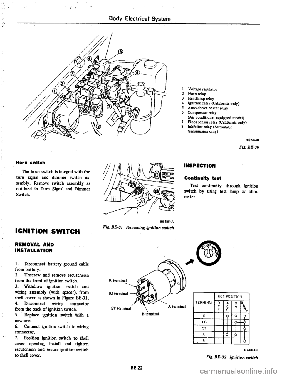
Horn
switch
The
horn
switch
is
integral
with
the
turn
signal
and
dimmer
switch
as
sembly
Remove
switch
assembly
as
outlined
in
Turn
Signal
and
Dimmer
Switch
IGNITION
SWITCH
BE861A
Fig
BE
3
I
Removing
ignition
switch
REMOVAL
AND
INSTALLATION
I
Disconnect
battery
ground
cable
from
battery
2
Unscrew
and
remove
escutcheon
from
the
front
of
ignition
switch
3
Withdraw
ignition
switch
and
wiring
assembly
with
spacer
from
shell
cover
as
shown
in
Figure
BE
3
4
Disconnect
wiring
connector
from
the
back
of
ignition
switch
5
Replace
ignition
switch
with
a
new
one
6
Connect
ignition
switch
to
wiring
connector
7
Position
ignition
switch
to
shell
cover
opening
install
and
tighten
escutcheon
and
secure
ignition
switch
to
shell
cover
R
terminal
1G
terminal
ST
terminal
B
terminal
8E
22
1
Voltage
regulator
2
Horn
relay
3
Headlamp
relay
4
Ignition
relay
California
only
5
Auto
choke
heater
relay
6
Compressor
relay
Au
conditioner
equipped
model
7
Floor
sensor
relay
California
only
8
Inhibitor
relay
Automatic
tran5mission
only
INSPECTION
BE683B
Fig
BE
30
ContInuity
test
Test
continuity
through
ignition
switch
by
using
test
lamp
or
ohm
meter
C
A
terminal
TERMINAL
0
F
F
B
IG
ST
A
R
KEY
FOSITlON
t
1
o
j
u
u
I
I
A
C
C
Fig
BE
32
Ignition
witch
BE6848
Page 481 of 537

CD
m
Cl
@
D
@
I
j
1
To
instrument
harness
IS
To
battery
30
To
check
connector
2
To
full
transistor
amplifier
16
To
fusible
link
3t
To
headlamp
L
U
type
2
California
models
only
17
To
engine
harness
No
2
32
To
sido
marker
lamp
L
B
3
To
hood
switch
18
To
alternator
33
To
front
combination
lamp
L
H
4
To
engine
compartment
lamp
1
9
To
front
combination
lamp
R
n
34
To
horn
Low
ll
l
S
To
washer
motor
20
To
headlamp
R
H
type
2
3S
To
horn
High
l
l
0
6
To
auto
choke
heater
relay
1
To
side
marker
lamp
R
n
36
To
B
C
D
D
cut
olenoid
California
models
7
To
detector
dri
e
counter
22
To
headlamp
R
B
type
1
only
Non
Califunia
model
except
for
Canada
23
To
ground
37
To
block
tcrminal
distributor
California
8
To
ignition
relay
California
models
only
i4
To
thermal
transmitter
models
only
9
To
floor
sensor
relay
California
modeb
only
is
To
distributor
Non
California
models
only
38
To
ignition
coil
Non
California
models
only
n
10
To
inhibitor
relay
A
T
only
26
To
8
C
D
D
cut
solenoid
Non
California
39
To
condenser
t
II
To
head
lamp
relay
models
only
40
To
ignition
coil
and
resistor
@
12
To
horn
relay
27
To
fuel
cut
solenoid
California
models
only
OJ
v
m
13
To
voltage
regulator
28
To
auto
choke
heater
g
e
14
To
cooler
cable
29
To
headlamp
L
R
type
1
OJ
to
o
Q
m
r0
C
1
i
Ql
CIl
Il
l
3
Page 487 of 537
G
t
Q8
Gt
Gt
t
Q
8
Gt
d8
t
QR
8
t
QR
LQR
8
@
RB
1ii
@
@
Gt
tp
o
c
l
T
S
O
i
CD
LQR
t
Q8
RB
8
G
8
Bt
J
rJl
1
3
1
1
0
instrUment
haltl
s
1
To
cooler
harnesS
fo
floor
sensor
California
models
ou
y
4
To
driver
belt
switch
5
To
tank
unit
6
1
0
side
marker
lamp
R
H
7
to
reat
combination
lamp
R
H
To
i
cens
e
amp
9
To
rear
combination
tarnP
L
lt
10
10
side
market
lamp
L
ll
8
@
c
8
ill@
Page 488 of 537

Body
Electrical
System
EMISSION
WARNING
SYSTEM
California
models
CONTENTS
FLOOR
TEMPERATURE
WARNING
SYSTEM
California
models
DESCRIPTION
FLOOR
TEMPERATURE
WARNING
SYSTEM
California
models
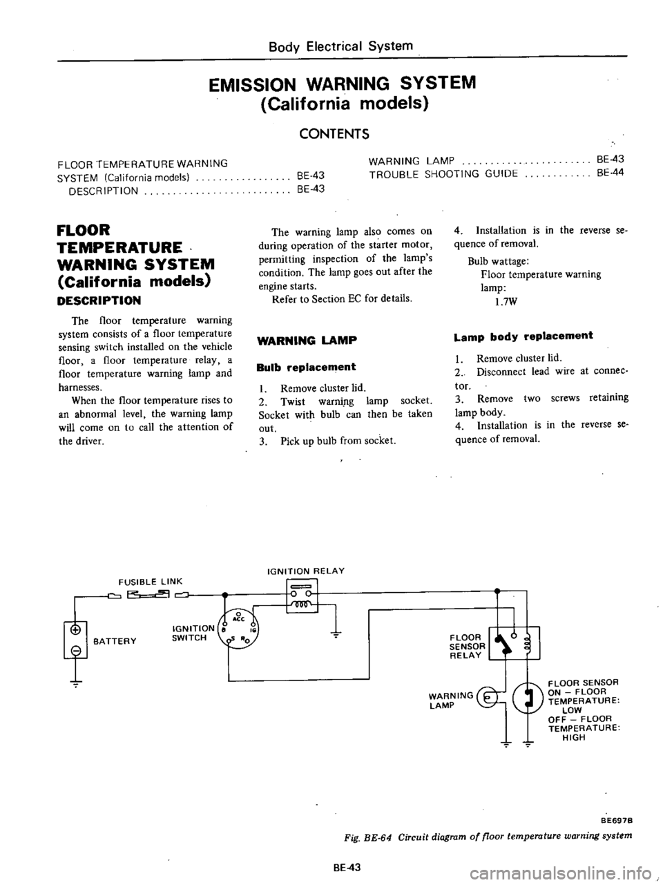
DESCRIPTION
The
floor
temperature
warning
system
consists
of
a
floor
temperature
sensing
switch
installed
on
the
vehicle
floor
a
floor
temperature
relay
a
floor
temperature
warning
lamp
and
harnesses
When
the
floor
temperature
rises
to
an
abnormal
level
the
warning
lamp
will
come
on
to
call
the
attention
of
the
driver
i
f
FUSIBLE
LINK
P
BATTERY
IGNITION
SWITCH
BE
43
8E
43
WARNING
LAMP
TROUBLE
SHOOTING
GUIDE
BE
43
BE
44
The
warning
lamp
also
comes
on
during
operation
of
the
starter
motor
permitting
inspection
of
the
lamp
s
condition
The
lamp
goes
out
after
the
engine
starts
Refer
to
Section
EC
for
details
WARNING
LAMP
Bulb
replacement
I
Remove
cluster
lid
2
Twist
warni
ng
lamp
socket
Socket
with
bulb
can
then
be
taken
out
3
Pick
up
bulb
from
socket
IGNITION
RELAY
I
I
4
Installation
is
in
the
reverse
se
quence
of
removaL
Bulb
wattage
Floor
temperature
warning
lamp
17W
Lamp
body
replacement
I
Remove
cluster
lld
2
Disconnect
lead
wire
at
connee
tor
3
Remove
two
screws
retaining
lamp
body
4
Installation
is
in
the
reverse
se
quence
of
removal
FLOOR
I
l
I
SENSOR
RELAY
WARNING
I
LAMP
FLOOR
SENSOR
ON
FLOOR
TEMPERATURE
LOW
OFF
FLOOR
TEMPERATURE
HIGH
7
BE697B
Fig
BE
64
Circuit
diagram
of
floor
temperature
warning
system
BE
43