Page 475 of 537

TEMP
lever
1
Move
TEMP
lever
to
the
OFF
position
2
Connect
control
cable
to
the
lever
of
water
ock
when
water
cock
lever
is
pulled
forward
fully
closed
3
Install
control
cable
on
water
cock
bracket
with
cable
retaining
clip
SPECIFICATIONS
Item
FAN
MOTOR
Rated
power
consumption
Revolution
rpm
Fan
dia
mm
in
TACHOMETER
The
tachometer
is
optional
on
model
HL620
It
is
an
integral
part
of
the
ignition
system
It
counts
the
pulses
entering
the
ignition
coil
and
indicates
the
number
of
engine
revolu
tions
REPLACEMENT
I
Remove
battery
ground
cable
2
Remve
cluster
lid
following
instructions
iri
steps
I
to
4
of
Removal
in
Combination
Meter
Body
Electrical
System
BE872A
Fig
BE
52
Water
cock
General
use
Extremely
cold
weather
use
2
RG
The
red
with
green
stripe
lead
wire
must
be
connected
to
flat
plate
terminal
at
back
of
combination
meter
3
B
The
black
lead
wire
must
be
connected
to
T
shaped
ter
minal
at
back
of
combination
meter
4
YR
The
yellow
with
red
stripe
lead
wire
must
be
connected
to
pole
terminal
at
back
of
combination
meter
6
Pass
tachllmeter
wires
through
grommet
on
hood
lock
control
wire
and
connect
to
negative
terminal
of
ignition
coil
Notes
a
Fix
grommet
with
an
adhesive
tape
or
a
sealing
compound
to
prevent
water
leakage
b
Attach
tachometer
wires
to
hood
lock
control
wire
with
an
adhesive
tape
BULB
REPLACEMENT
I
Remove
tachometer
as
previously
described
2
Twist
illumination
bulh
socket
at
back
of
tachometer
Bulb
with
socket
can
then
be
easily
removed
3
Remove
bulb
4
Install
new
bulb
in
reverse
se
quence
of
removal
Bulb
wattage
Tachometer
illumination
lamp
3
4W
12V
less
than
36W
3
600
110
433
12V
less
than
SSW
2
SOO
110
4
33
3
Disconnect
four
tachometer
lead
wire
connectors
They
are
connected
to
combination
meter
and
tachometer
cable
4
Remove
three
screws
and
then
remove
tachometer
from
cluster
lid
5
Install
in
reverse
sequence
of
re
moval
When
connecting
lead
wire
note
the
following
1
BW
The
black
with
white
striped
lead
wire
must
be
connected
to
identically
colored
ta
chometer
cable
coming
from
engine
compartment
BE
30
BE965
Fig
BE
53
Tachometer
Page 476 of 537

SEAT
BELT
WARNING
SYSTEM
DESCRIPTION
Except
Canada
When
the
ignition
switch
is
turned
to
the
ON
position
the
warning
lamp
comes
on
and
remains
on
for
4
to
8
seconds
The
warning
buzzer
sounds
for
4
to
8
seconds
intermittent
ly
if
the
driver
s
seat
belt
is
not
fastened
properly
The
seat
belt
warning
system
con
sists
of
a
driver
s
belt
switch
a
warning
buzzer
a
warning
lamp
a
timer
unit
and
an
ignition
switch
For
Canada
When
the
ignition
switch
is
turned
Body
Electrical
System
to
the
ON
position
the
warning
lamp
comes
on
and
the
warning
buz
zer
sounds
if
the
driver
s
seat
belt
is
not
fastened
properly
The
seat
belt
warning
system
con
sists
of
a
driver
s
belt
switch
a
warning
buzzer
a
warning
lamp
and
an
igni
tion
switch
REMOVAL
AND
INSTALLATION
Ignition
switch
Refer
to
page
BE
22
for
Removal
and
Installation
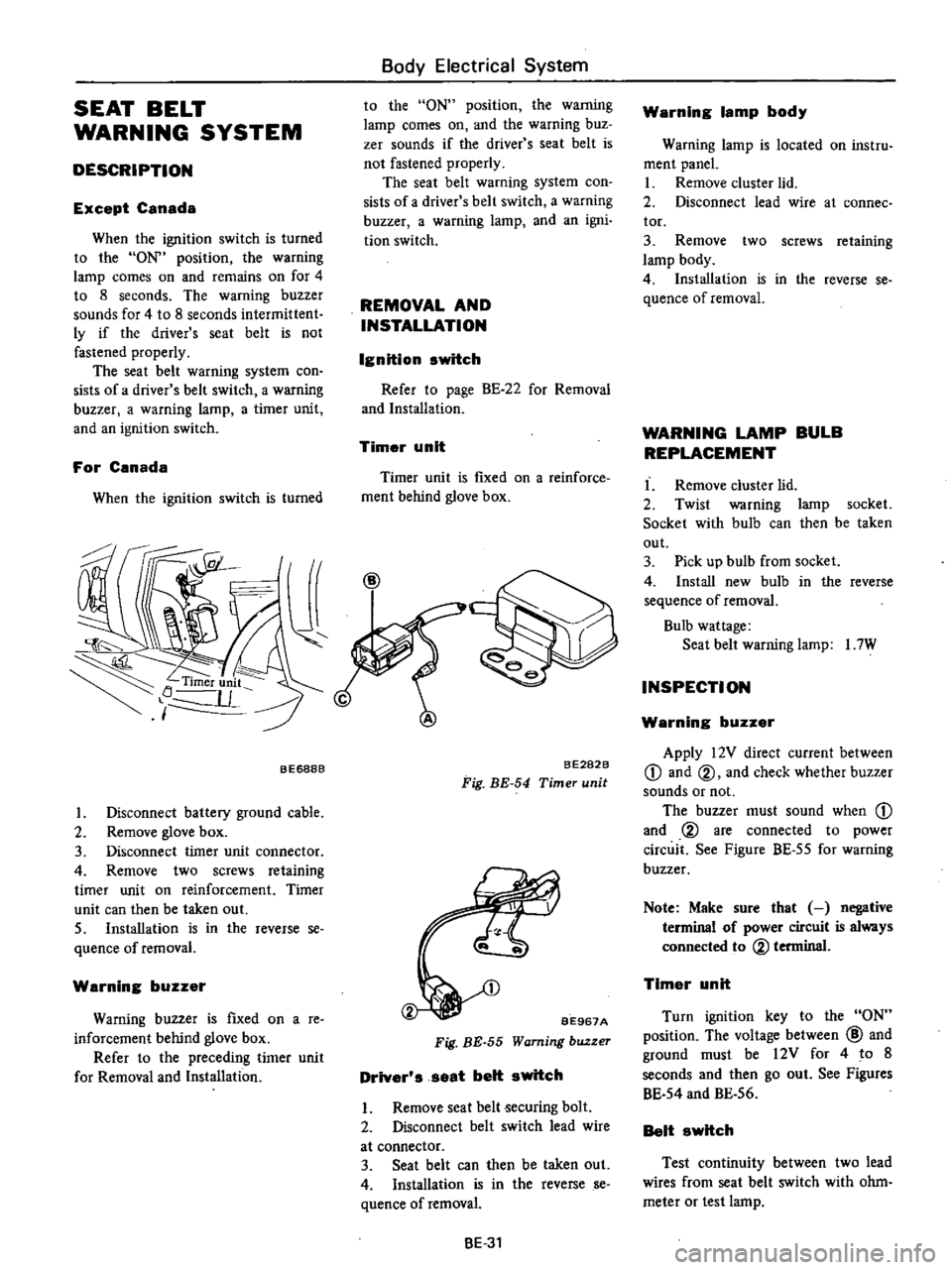
Timer
unit
Timer
unit
is
fIXed
on
a
reinforce
ment
behind
glove
box
BE688B
I
Disconnect
battery
ground
cable
2
Remove
glove
box
3
Disconnect
timer
unit
connector
4
Remove
two
screws
retaining
timer
unit
on
reinforcement
Timer
unit
can
then
be
taken
out
S
Installation
is
in
the
reverse
se
quence
of
removal
Warning
buzzer
Warning
buzzer
is
fIxed
on
a
re
inforcement
behind
glove
box
Refer
to
the
preceding
timer
unit
for
Removal
and
Installation
BE282B
Fig
BE
54
Timer
unit
BE967A
Fig
BE
55
Warning
buzzer
Driver
s
seat
belt
switch
I
Remove
seat
belt
ecuring
bolt
2
Disconnect
belt
switch
lead
wire
at
connector
3
Seat
belt
can
then
be
taken
out
4
Installation
is
in
the
reverse
se
quence
ofremoval
BE
31
Warning
lamp
body
Warning
lamp
is
located
on
instru
ment
panel
I
Remove
cluster
lid
2
Disconnect
lead
wire
at
connee
tor
3
Remove
two
screws
retaining
lamp
body
4
Installation
is
in
the
reverse
se
quence
of
removal
WARNING
LAMP
BULB
REPLACEMENT
I
Remove
cluster
lid
2
Twist
warning
lamp
socket
Socket
with
bulb
can
then
be
taken
out
3
Pick
up
bulb
from
socket
4
Install
new
bulb
in
the
reverse
sequence
of
removal
Bulb
wattage
Seat
belt
warning
lamp
I
7W
INSPECTION
Warning
buzzer
Apply
12V
direct
current
between
CD
and
@
and
check
whether
buzzer
sounds
or
not
The
buzzer
must
sound
when
CD
and
@
are
connected
to
power
circuit
See
Figure
BE
55
for
warning
buzzer
Note
Make
sure
that
negative
terminal
of
power
circuit
is
always
connected
to
@
terminal
Timer
unit
Turn
ignition
key
to
the
ON
position
The
voltage
between
@
and
ground
must
be
12V
for
4
to
8
seconds
and
then
go
out
See
Figures
BE
54
and
BE
56
Belt
switch
Test
continuity
between
two
lead
wires
from
seat
belt
switch
with
ohm
meter
or
test
lamp
Page 488 of 537

Body
Electrical
System
EMISSION
WARNING
SYSTEM
California
models
CONTENTS
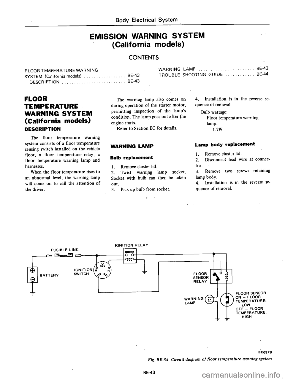
FLOOR
TEMPERATURE
WARNING
SYSTEM
California
models
DESCRIPTION
FLOOR
TEMPERATURE
WARNING
SYSTEM
California
models
DESCRIPTION
The
floor
temperature
warning
system
consists
of
a
floor
temperature
sensing
switch
installed
on
the
vehicle
floor
a
floor
temperature
relay
a
floor
temperature
warning
lamp
and
harnesses
When
the
floor
temperature
rises
to
an
abnormal
level
the
warning
lamp
will
come
on
to
call
the
attention
of
the
driver
i
f
FUSIBLE
LINK
P
BATTERY
IGNITION
SWITCH
BE
43
8E
43
WARNING
LAMP
TROUBLE
SHOOTING
GUIDE
BE
43
BE
44
The
warning
lamp
also
comes
on
during
operation
of
the
starter
motor
permitting
inspection
of
the
lamp
s
condition
The
lamp
goes
out
after
the
engine
starts
Refer
to
Section
EC
for
details
WARNING
LAMP
Bulb
replacement
I
Remove
cluster
lid
2
Twist
warni
ng
lamp
socket
Socket
with
bulb
can
then
be
taken
out
3
Pick
up
bulb
from
socket
IGNITION
RELAY
I
I
4
Installation
is
in
the
reverse
se
quence
of
removaL
Bulb
wattage
Floor
temperature
warning
lamp
17W
Lamp
body
replacement
I
Remove
cluster
lld
2
Disconnect
lead
wire
at
connee
tor
3
Remove
two
screws
retaining
lamp
body
4
Installation
is
in
the
reverse
se
quence
of
removal
FLOOR
I
l
I
SENSOR
RELAY
WARNING
I
LAMP
FLOOR
SENSOR
ON
FLOOR
TEMPERATURE
LOW
OFF
FLOOR
TEMPERATURE
HIGH
7
BE697B
Fig
BE
64
Circuit
diagram
of
floor
temperature
warning
system
BE
43