1977 DATSUN PICK-UP air suspension
[x] Cancel search: air suspensionPage 369 of 537

DESCRIPTION
The
rear
axle
assembly
is
of
the
semi
floating
type
in
which
the
vehicle
weight
is
carried
on
the
axle
shafts
through
bearings
enclosed
in
the
bear
ing
cages
on
outer
rear
axle
case
The
axle
case
is
a
pressed
steeJ
Banjo
type
housing
The
rear
axle
assembly
is
attached
to
the
frame
through
semi
elliptic
leaf
springs
and
telescopic
hydraulic
shock
absorbers
Rubber
bushings
at
either
end
of
the
leaf
springs
and
shock
absorbers
are
designed
to
absorb
vibra
tion
and
noise
The
rear
axle
shaft
splines
engage
the
differential
side
gears
with
a
float
ing
fit
The
outer
ends
are
supported
in
the
bearing
cages
by
tapered
roller
bearings
The
bearings
are
lubricated
by
wheel
bearing
grease
The
axle
shaft
oil
seals
are
located
outboard
and
inboard
of
the
bearing
The
bearings
are
se
cured
against
shoulders
on
the
shafts
by
press
fit
and
held
in
place
by
a
large
nuts
The
bearing
cages
hold
the
bearings
against
shoulders
on
the
axle
case
Whee
side
thrust
is
taken
at
the
wheel
bearings
through
the
thrust
block
so
an
axle
shaft
may
be
re
moved
simply
by
removing
the
bolts
holding
the
brake
disc
to
the
bearing
cage
and
the
rear
axle
case
REMOVAL
AND
INSTALLATION
REAR
AXLE
ASSEMBLY
It
is
not
necessary
to
remove
the
reaT
axle
assembly
for
any
normal
repairs
However
if
the
axle
case
is
dam
aged
the
rear
axle
assembly
may
be
removed
and
installed
using
the
fol
lowing
procedures
I
Raise
rear
of
vehicle
high
enough
to
permi
t
working
underneath
Place
a
jack
under
center
of
axle
case
so
it
just
starts
to
raise
rear
axle
assembly
Place
stands
solidly
under
frame
members
on
both
sides
Remove
rear
wheels
Rear
Axle
Rear
Suspension
2
Mark
relationship
across
propeller
shaft
flange
and
companion
flange
of
differential
carrier
so
that
the
original
combination
is
restored
at
assembly
3
Remove
bolts
retaining
center
bearing
bracket
and
connecting
shaft
to
companion
flange
Withdraw
pro
peller
shaft
sleeve
yoke
from
transmis
sion
by
moving
the
shaft
rearward
passing
it
under
rear
axle
4
Disconnect
rear
hand
brake
cable
Q
by
removing
adjusting
nut
@
three
clamps
ID
and
connector
@
Slide
front
cable
rearward
and
discon
nect
rear
cable
@
at
connector
ID
by
removing
three
clamps
ID
5
Disconnect
rear
brake
hose
at
frame
@
Cover
brake
hose
and
pipe
openings
to
prevent
entrance
of
dirt
6
Disconnect
shock
absorbers
at
lower
end
f
and
push
shock
ab
sorbers
up
out
of
the
way
7
Lower
jack
under
axle
case
Re
move
U
bolts
spring
clips
@
to
separate
axle
case
from
spring
8
Place
a
jack
under
center
of
axle
case
Pass
axle
case
through
space
above
spring
and
take
it
out
to
the
side
RA134
Fig
RA
3
Removing
rear
axle
assembly
9
Install
the
axle
case
assembly
in
the
reverse
order
of
removal
RA
3
RA312
Fig
RA
2
Under
view
Tightening
torque
U
bolt
Spring
clip
7
3
to
9
9
kg
m
53
to
72
ft
lb
Shock
absorber
lower
end
nut
1
6
to
2
2
kg
m
12to
16ft
Ib
Brake
pipe
flare
nut
I
S
to
1
8
kg
m
II
to
13
ft
Ib
Propeller
shaft
to
companion
flange
connecting
bolt
2
0
to
2
7
kg
m
14
to
20
ft
Ib
Center
bearing
bracket
fixin
holt
1
6
to
2
2
kg
m
12
to
16
ft
Ib
Page 374 of 537

Rear
Axle
Rear
Suspension
Spring
front
pin
Spring
shackle
Bearing
cage
fIXing
bolt
Wheel
bearing
lock
nut
Air
breather
Differential
gear
carrier
to
axle
case
nut
Propeller
shaft
flange
bolt
Drain
and
filler
plug
Bumper
rubber
fixing
bolt
Wheel
nut
kg
m
ft
lb
kg
m
ft
Ib
kg
en
ft
lb
kg
m
ft
Ib
kg
m
ft
Ib
kg
m
ft
Ib
kg
en
ft
Ib
kg
m
ft
Ib
kg
m
ft
Ib
kg
m
ft
lb
11
5
to
13
0
83
to
94
11
5
to
13
0
83
to
94
S
4
to
6
4
39
to
46
IS
to
20
108
to
l4S
0
7
to
0
9
S
I
to
6
S
17
to
2
7
12
to
20
2
0
to
2
7
14
to
20
6
to
10
43
to
72
1
6
to
2
2
12
to
16
8
to
9
S8
to
6S
TROUBLE
DIAGNOSES
AND
CORRECTIONS
When
rear
axle
and
suspension
is
suspected
of
being
noisy
it
is
advisable
to
make
a
thorough
test
to
determine
whether
the
noise
originates
in
the
tires
road
surface
exhaust
propeller
shaft
engine
transmission
universal
joint
wheel
bearings
or
suspension
Noise
which
originates
in
other
places
can
not
be
corrected
by
adjust
ment
or
replacement
of
parts
in
the
rear
axle
and
rear
suspension
In
case
of
oil
leak
first
check
if
there
is
any
damage
or
restriction
in
breather
Condition
Probable
cause
Noise
Loose
wheel
nuts
Loose
one
or
more
securing
bolts
Lack
of
lubricating
oil
or
grease
Faulty
shock
absorber
Incorrect
adjustment
of
rear
axle
shaft
end
play
Damaged
or
worn
wheel
bearing
Worn
spline
portion
of
rear
axle
shaft
Broken
leaf
spring
Loose
journal
connections
or
so
no
Wheel
and
tire
unbalance
Damaged
rubber
parts
such
as
leaf
spring
bush
shock
absorber
moun
ting
bush
Faulty
universal
joints
Instability
in
driving
Loose
wheel
nuts
Worn
shock
absorber
Worn
or
broken
leaf
spring
Oil
leakage
Damaged
or
restricted
air
breather
Damaged
oil
seal
in
rear
axle
case
or
differ
ential
carrier
Oil
leakage
from
between
the
differential
carrier
and
axle
case
RA
8
Corrective
action
Tighten
the
wheel
nuts
Tighten
the
bolts
to
the
specified
torque
Lubricate
as
required
Replace
the
shock
absorber
Adjust
the
rear
axle
shaft
end
play
Replace
wheel
bearing
Replace
if
necessary
Replace
leaf
spring
Tighten
to
the
given
torque
Balance
wheel
and
tire
Replace
the
required
parts
Adjust
or
replace
Tighten
to
the
given
torque
Replace
faulty
shock
absorber
Replace
leaf
spring
Clean
or
replace
air
breather
Replace
the
damaged
oil
seal
Tighten
to
the
specified
torque
or
replace
gasket
Page 405 of 537

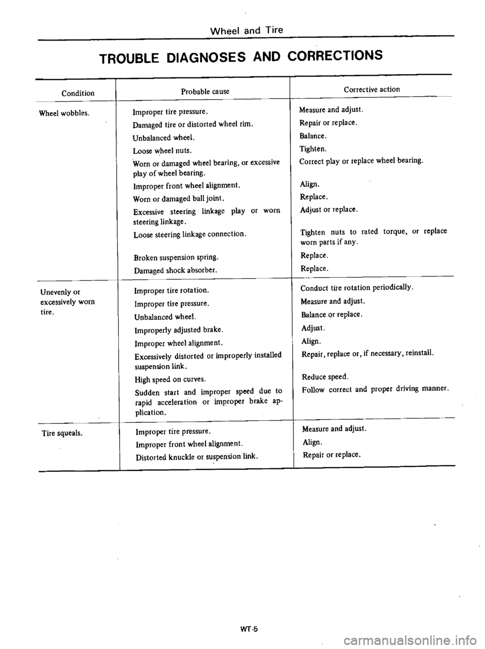
Condition
Wheel
wobbles
Unevenly
or
excessively
worn
tire
Tire
squeals
Wheel
and
Tire
TROUBLE
DIAGNOSES
AND
CORRECTIONS
Probable
cause
Improper
tire
pressure
Damaged
tire
or
distorted
wheel
rim
Unbalanced
wheel
Loose
wheel
nuts
Worn
or
damaged
wheel
bearing
or
excessive
play
of
wheel
bearing
Improper
front
wheel
alignment
Worn
or
damaged
ball
joint
Excessive
steering
linkage
play
or
worn
steering
linkage
Loose
steering
linkage
connection
Broken
suspension
spring
Damaged
shock
absorber
Improper
tire
rotation
Improper
tire
pressure
Unbalanced
wheel
Improperly
adjusted
brake
Improper
wheel
alignment
Excessively
distorted
or
improperly
installed
suspension
link
High
speed
on
curves
Sudden
start
and
improper
speed
due
to
rapid
acceleration
or
improper
brake
ap
plication
Improper
tire
pressure
Improper
front
wheel
alignment
Distorted
knuckle
or
suspension
link
WT
5
Corrective
action
Measure
and
adjust
Repair
or
replace
Balance
Tighten
Correct
play
or
replace
wheel
bearing
Align
Replace
Adjust
Or
replace
Tighten
nuts
to
rated
torque
or
replace
worn
parts
if
any
Replace
Replace
Conduct
tire
rotation
periodically
Measure
and
adjust
Balance
or
replace
Adjust
Align
Repair
replace
or
if
necessary
reinstall
Reduce
speed
Follow
correct
and
proper
driving
manner
Measure
and
adjust
Align
Repair
or
replace
Page 414 of 537

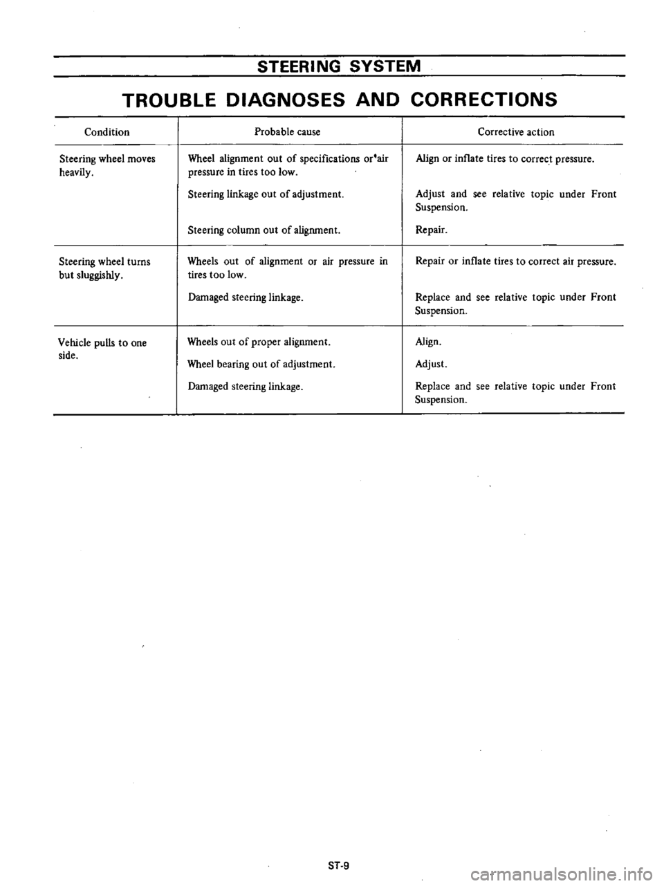
STEERING
SYSTEM
TROUBLE
DIAGNOSES
AND
CORRECTIONS
Condition
Steering
wheel
moves
heavily
Steering
wheel
turns
but
sluggishly
Vehicle
pulls
to
one
side
Probable
cause
Wheel
alignment
out
of
specifications
or
air
pressure
in
tires
too
low
Steering
linkage
out
of
adjustment
Steering
column
out
of
alignment
Wheels
out
of
alignment
or
air
pressure
in
tires
too
low
Damaged
steering
linkage
Wheels
out
of
proper
alignment
Wheel
bearing
out
of
adjustment
Damaged
steering
linkage
ST
9
Corrective
action
Align
or
inflate
tires
to
correct
pressure
Adjust
and
see
relative
topic
under
Front
Suspension
Repair
Repair
or
inflate
tires
to
correct
air
pressure
Replace
and
see
relative
topic
under
Front
Suspension
Align
Adjust
Replace
and
see
relative
topic
under
Front
Suspension