Page 76 of 537

Engine
Mechanical
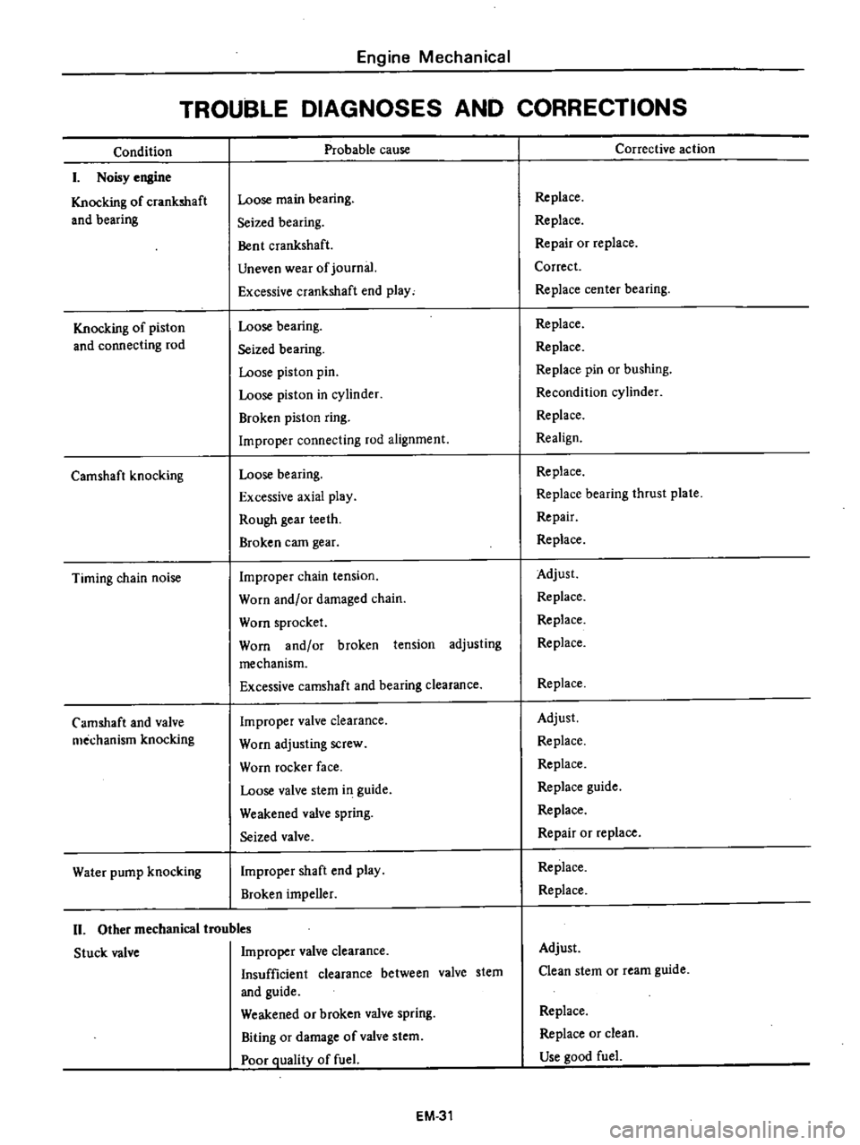
TROUBLE
DIAGNOSES
AND
CORRECTIONS
Condition
I
Noisy
engine
Knocking
of
crankshaft
and
bearing
Knocking
of
piston
and
connecting
rod
Camshaft
knocking
Timing
chain
noise
Camshaft
and
valve
mechanism
knocking
Water
pump
knocking
Probable
cause
Loose
main
bearing
Seized
bearing
Bent
crankshaft
Uneven
wear
of
journal
Excessive
crankshaft
end
play
Loose
bearing
Seized
bearing
Loose
piston
pin
Loose
piston
in
cylinder
Broken
piston
ring
Improper
connecting
rod
alignment
Loose
bearing
Excessive
axial
play
Rough
gear
teeth
Broken
eam
gear
Improper
chain
tension
Worn
and
or
damaged
chain
Worn
sprocket
Worn
and
or
broken
tension
adjusting
mechanism
Excessive
camshaft
and
bearing
clearance
Improper
valve
clearance
Worn
adjusting
screw
Worn
rocker
face
Loose
valve
stem
i1
1
guide
Weakened
valve
spring
Seized
valve
Improper
shaft
end
play
Broken
impeller
II
Other
mechanical
troubles
Stuck
valve
Improper
valve
clearance
Insufficient
clearance
between
valve
stem
and
guide
Weakened
or
broken
valve
spring
Biting
or
damage
of
valve
stem
Poor
Quality
of
fuel
EM
31
Corrective
action
Replace
Replace
Repair
or
replace
Correct
Replace
cen
ter
bearing
Replace
Replace
Replace
pin
or
bushing
Recondition
cylinder
Replace
Realign
Replace
Replace
bearing
thrust
plate
Repair
Replace
Adjust
Replace
Replace
Replace
Replace
Adjust
Replace
Replace
Replace
guide
Replace
Repair
or
replace
Replace
Replace
Adjust
Clean
stem
or
ream
guide
Replace
Replace
or
clean
Use
ood
fuel
Page 85 of 537

ENGINE
LUBRICATION
SYSTEM
ENGINE
LUBRICATION
SYSTEM
CONTENTS
LUBRICATION
CIRCUIT
01
L
PUMP
Removal
Installation
Disassembly
and
assembly
EL
2
EL
2
EL
2
EL
2
EL
3
Inspection
OIL
PRESSURE
REGULATOR
VALVE
OIL
FILTER
RELIEF
VALVE
EL
3
EL
4
EL
4
EL
4
E
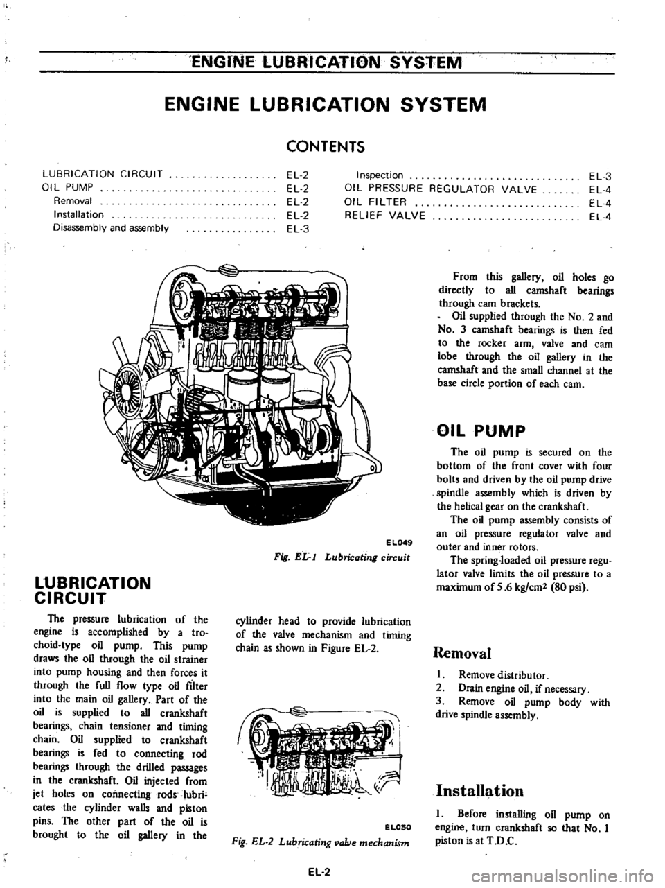
L049
Fig
Elr
I
Lubricating
circuit
LUBRICATION
CIRCUIT
The
pressure
lubrication
of
the
engine
is
accomplished
by
a
tro
choid
type
oil
pump
This
pump
draws
the
oil
through
the
oil
strainer
into
pump
housing
and
then
forces
it
through
the
full
flow
type
oil
filter
into
the
main
oil
gallery
Part
of
the
oil
is
supplied
to
all
crankshaft
bearings
chain
tensioner
and
timing
chain
Oil
supplied
to
crankshaft
bearings
is
fed
to
connecting
rod
bearings
through
the
drilled
passages
in
the
crankshaft
Oil
injected
from
jet
holes
on
connecting
rods
Iubri
cates
the
cylinder
walls
and
piston
pins
The
other
part
of
the
oil
is
brought
to
the
oil
gallery
in
the
cylinder
head
to
provide
lubrication
of
the
valve
mechanism
and
timing
chain
as
shown
in
Figure
EL
2
ELOSO
Fig
EL
2
Lubricating
vallie
mechanism
EL
2
From
this
gallery
oil
holes
go
directly
to
all
camshaft
bearings
through
cam
brackets
Oil
supplied
through
the
No
2
and
No
3
camshaft
bearings
is
then
fed
to
the
rocker
arm
valve
and
eam
lobe
through
the
oil
gallery
in
the
camshaft
and
the
small
channel
at
the
base
circle
portion
of
each
earn
OIL
PUMP
The
oil
pump
is
secured
on
the
bottom
of
the
front
cover
with
four
bolts
and
driven
by
the
oil
pump
drive
spindle
assembly
which
is
driven
by
the
helical
gear
on
the
crankshaft
The
oil
pump
assembly
consists
of
an
oil
pressure
regulator
valve
and
outer
and
inn
r
rotors
The
spring
loaded
oil
pressure
regu
lator
valve
limits
the
oil
pressure
to
a
maximum
of
5
6
kg
em
80
psi
Removal
I
Remove
distributor
2
Drain
engine
oil
if
necessary
3
Remove
oil
pump
body
with
drive
spindle
assembly
Installation
I
Before
installing
oil
pump
on
engine
turn
crankshaft
so
that
No
I
piston
is
at
TD
C
Page 91 of 537

DESCRIPTION
COOLANT
LEVEL
DRAINING
AND
FLUSHING
THE
COOLING
SYSTEM
WATER
PUMP
REMOVAL
AND
INSTALLATION
DISASSEMBLY
INSPECTION
AND
ADJUSTMENT
TORQUE
COUPLING
REMOVAL
AND
INSTALLATION
DESCRIPTION
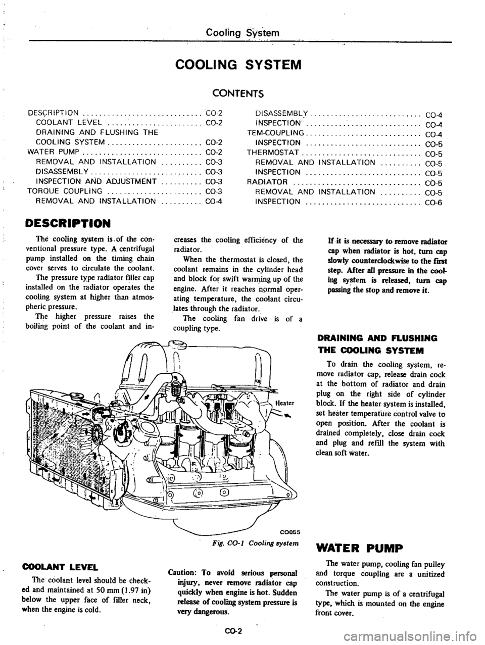
The
cooling
system
is
of
the
con
ventional
pressure
type
A
centrifugal
pump
installed
on
the
timing
chain
cover
serves
to
circulate
the
coolant
The
pressure
type
radiator
filler
cap
installed
on
the
radiator
operates
the
cooling
system
at
higher
than
atmos
pheric
pressure
The
higher
pressure
raises
the
boiling
point
of
the
coolant
and
in
Cooling
System
COOLING
SYSTEM
CONTENTS
CO
2
CO
2
OISASSEMBL
Y
INSPECTION
TEM
COUPLlNG
INSPECTION
THERMOSTAT
REMOVAL
AND
INSTALLATION
INSPECTION
RADIATOR
REMOVAL
AND
INSTALLATION
INSPECTION
CO
2
CO
2
CO
3
CO
3
CO
3
CO
3
CO
4
creases
the
cooling
efficiency
of
the
radiator
When
the
thermostat
is
closed
the
coolant
remains
in
the
cylinder
head
and
block
for
swift
warming
up
of
the
engine
After
it
reaches
normal
oper
ating
temperature
the
coolant
circu
lates
through
the
radiator
The
cooling
fan
drive
is
of
a
coupling
type
COOLANT
LEVEL
The
coolant
level
should
be
check
ed
and
maintained
at
SO
mm
1
97
in
below
the
upper
face
of
filler
neck
when
the
engine
is
cold
C0055
Fig
CO
I
Cooling
ry
lem
Caution
To
avoid
serious
personal
injury
never
remove
I3diator
cap
quickly
when
engine
is
hot
Sudden
release
of
cooling
system
pressure
is
very
dangerous
CO
2
CO
4
CO
4
CO
4
CO
5
CO
5
CO
5
CO
5
CO
5
CO
5
CO
6
If
it
is
necessary
to
remove
radiator
cap
wben
radiator
is
hot
turn
cap
slowly
counterclockwise
to
the
r
step
After
all
pressure
in
the
cool
ing
system
is
released
tom
cap
passing
the
stop
and
remove
it
DRAINING
AND
FLUSHING
THE
COOLING
SYSTEM
To
drain
the
cooling
system
re
move
radiator
cap
release
drain
cock
at
the
bottom
of
radiator
and
drain
plug
on
the
right
side
of
cylinder
block
If
the
heater
system
is
installed
set
heater
temperature
control
valve
to
open
position
After
the
coolant
is
drained
completely
close
drain
cock
and
plug
and
refill
the
system
with
clean
soft
water
WATER
PUMP
The
water
pump
cooling
fan
pulley
and
torque
coupling
are
a
unitized
construction
The
water
pump
is
of
a
centrifugal
type
which
is
mounted
on
the
engine
front
cover