1976 CHEVROLET MONTE CARLO lock
[x] Cancel search: lockPage 32 of 102
Downloaded from www.Manualslib.com manuals search engine vides ventilation . coillfort , made
possible
by the additionaf air veilt
provisions ' in the rear 1:>ody lock
pillar. Another feature of the
sys
tem is continuous low:speed opera
tion of the heater and air condi
tioner blower , resulting in an un
interrupted
supply of outside air
flOw into the car whenever the
ignition switch is.on. With
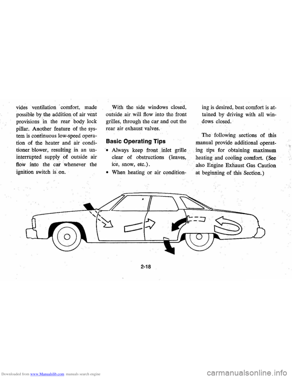
the side windows closed,
out side air will
flow into the front
grilles, through the car and out the
rear air exhaust valves.
Basic Operating Tips
'. Always keep front Jnlet grille
clear of obstructions (leaves,
ice, snow, etc.).
• When heating or air condition-
2-18
ingis desired , best comfort is at
tained by driving with all win
dows closed.
The following sections of this
manual provide additional operat-
. ing tips for obtaining maximum
heating and
cooling comfort. (See
also Engine Exnaust Gas Caution
at beginning of
this Seotion.)
Page 34 of 102
Downloaded from www.Manualslib.com manuals search engine • For most satisfactory heater op
eration and air circulation , oper
ate fan on low or medium speeds
for normal operation and high
s peeds for quick warm -up and
during extremely low
tempera
tures.
• For adeq uate rear sea t he ating,
the area beneath the front seat
mus not be block ed by carpet
ing, rags, paper or oth er mate
rial and fan sh ould operate on
high blower.
Rear Window Defroster
To ensure clear vision through
the rear
window during inclem ent
weather , the Rear Window
De
froster is optionally available. This
unit dr
aws. in air from the pas
senger compart ment and directs it
aga inst the back window to remove
frost or moisture. Its blower h
as a
two-speed control switch on the
instrument panel.
Four Season Air Conditioning System
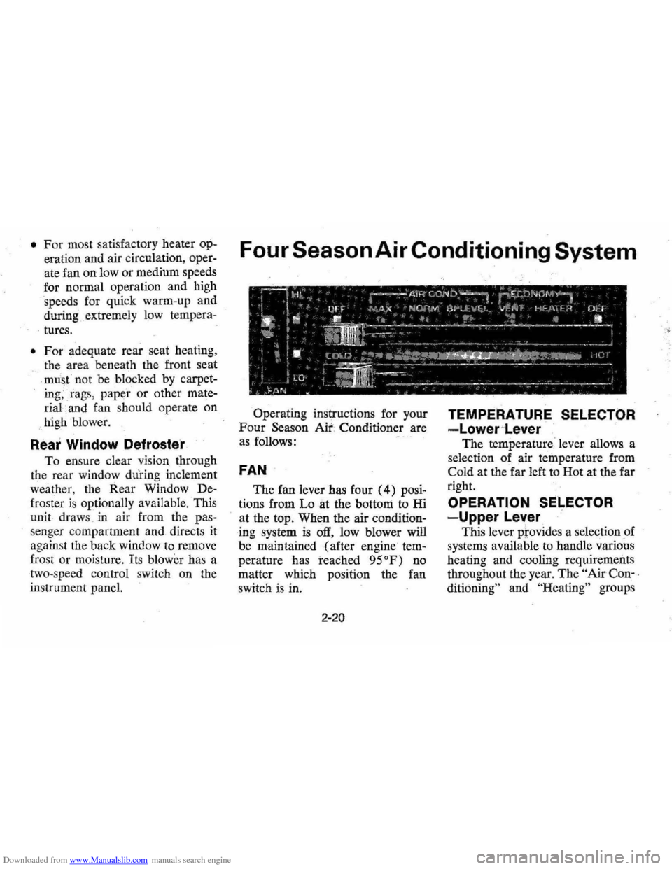
Operating instructions for your
Four Season Air Conditioner are
a s follows:
FAN
The fan lever has four (4) posi
tions from Lo at the bottom to Hi
at the top. When the air
condition
ing system is off, low blower will
be maintained (after engine
tem
perature has reached 95°F) no
matter which positi on the fan
switch is in.
2-20
TEMPERATURE SELECTOR
-Lower~Lever
The temperature ' lever allows a
selection of air temperature from
Cold at the far left to Hot at the far
right.
OPERATION SELECTOR
-Upper Lever
This lever prov ides a selection of
systems available to handle various
heating and cooling requirements
throughout the year.
The " Air Con-,
ditioning"
an d "He ating" groups
Page 39 of 102

Downloaded from www.Manualslib.com manuals search engine Chevrolet "AU Transistor" Radios
To operate the radios, the igni
tion switch must be in "ON" or
"ACC" position .
Push Button AM Radio
In addition to the manual con
trols, the Push Bu.tton Radio pro
vides five push buttons with which
to automatically
select preset sta
tions. To preset, pull the push but
ton "out" as far as it will go, tune
in the desired station . manually
and then
push" the button "in."',
Repeat this ope(ation for each push ,
button.
AM/FM Radio
In addition to providing stand'
ard AM reception, this set permits
you to receive clear
static:{ree FM:
broadcasts. Move the slide bar,
above the radio dial, to the right
or
left to select AM or PM reception.
All
other controls remain the same
as described for Push Buttonra
dios. FM broadcasts may be re
ceived as far as 25 miles from the
sending station, depending on the
power of the station and the
exist
ing terrain .' In fringe areas , it may
be possible to retune the radio
slightly tornaintain peak reception.
If not, retune to a closer or strong
er FM station or switch to AM
operation.
Push buttons may be
set for both
AM or J;1M stations as
follows: j
• Place slide bar in AM position.
• Pull push button out as far as it
will go, tune in desired AM
sta
tion manually and then push
button in to lock in position.
• Repeat for each remaining push
button .
2-25
-"------~~ ..... ~ " IM~ rill< ~1111----;; ,...
• Place slide bar in FM position
and repeat procedures outlined
for
AM band setting.
NOTE: Bands cannot be changed
if push button
is unlocked.
Antenna
The radio antenna is incorpo,
rated in the windshield glass. If
necessary , adjustments for maxi
mum antenna effectiveness can be
made by your authorized Chevrolet
dealer.
Page 41 of 102
Downloaded from www.Manualslib.com manuals search engine OTHER CONTROLS AND FEATURES
PO$itraction Rea~ Axle
The optional Positraction axle
can provide
additional traction on
snow, ice, mud,
s~d; gravel,etc.
During
normal :4riving and cor
nering, the Positraction unit func
tions as a standard : axle. However ;
when either
drIv&\vheel encounters
a slippery,enoug~urface,the Po;i,
traction can ~i>~~ue to provide
driving force
to.: the wheel havin,g
the greatertr~ction, in,stead of
merely
'" the wheel which
has the least
tra,c:tion.
Power Door Locks
The optionally : available power
door
lo~ks allow you to unlock
, or lock your doors by operating
the switch marked
"LOCK" located
on either door panel. The
auto
matic locking mechanism does not,
at any time, interfere with
mart,ual
operation of any door lock button.
The doors
will not unlock or open
with the inside door handle when
the lock button
is depressed, but
can be unlock .ed individually by
lifting the lock button.
Root~uggag, Carrier
The optionalcarrier allows load
ing of items onto the roof of your
station
~~~;;;;
stricts the projection of car
ried on vehides, not to extend be
yond the left side fender line, nor
2-27
more than six .inches beyond the
right side fender line. Check your
local regulations.
Superlift Air Adjustable
Shock
Absorbers
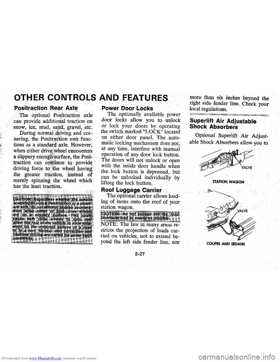
Optional Superlift Air Adjust
able Shock Absorbers allow you to
STATIO,.. WAGON
COUPES AND SEDANS
Page 43 of 102
Downloaded from www.Manualslib.com manuals search engine OPERATION OF FOLDING SEATS
The second and third seats of the
three-seat station wagon are de- signed so they
can be converted
into load floors-or into seats from
2-29
NOTE: If the intemal power window con
trol falls to operate the tailgate· window,
It Is probable:the window will· still be oper~
able by means of the exterior key switch
at the rear of the vehicle.
the right rear door opening.
Two-Seat Style Rear Seat
1. Release the locking lever on
Page 44 of 102
Downloaded from www.Manualslib.com manuals search engine the right hand side of the rear
seat back.
2.
Pull seat back forward and
down.
3. To raise the seat, lean on the
front edge of the
seat back
pimet to remove ctehsion from
the filler panel,
liit up the filler
pan¢l, then lift .seat back up
and rearward until it locks into
place.
Three-Seat Sfitle Seats
Second Seat Operation '" ' ;
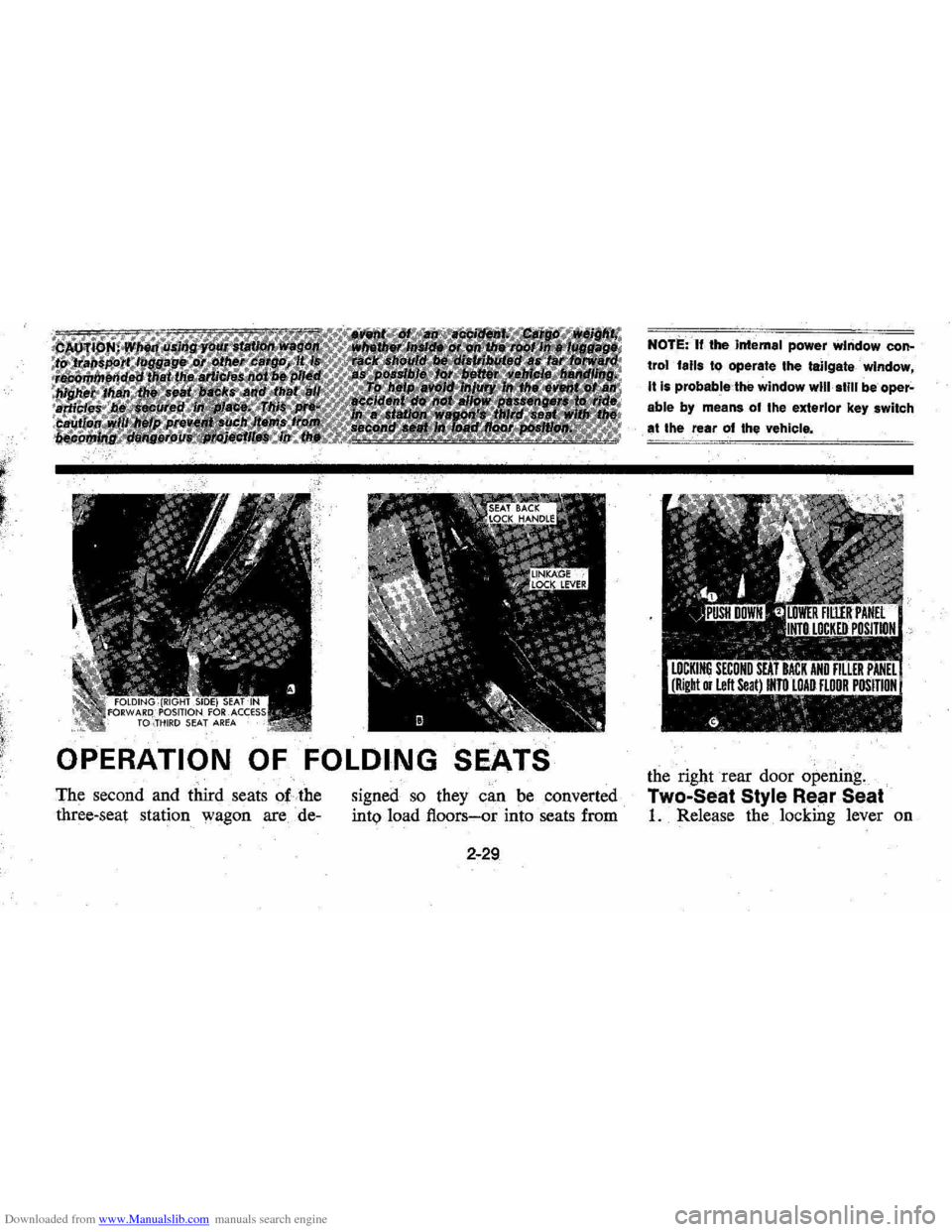
1. TO,move the right side of the
second seat forward for access
or entrance into the third seat
area, unlock the seat
by pulling
forward the upper lock lever at
the right side of the seat back,
then push the seat back forward
which will move the entire right
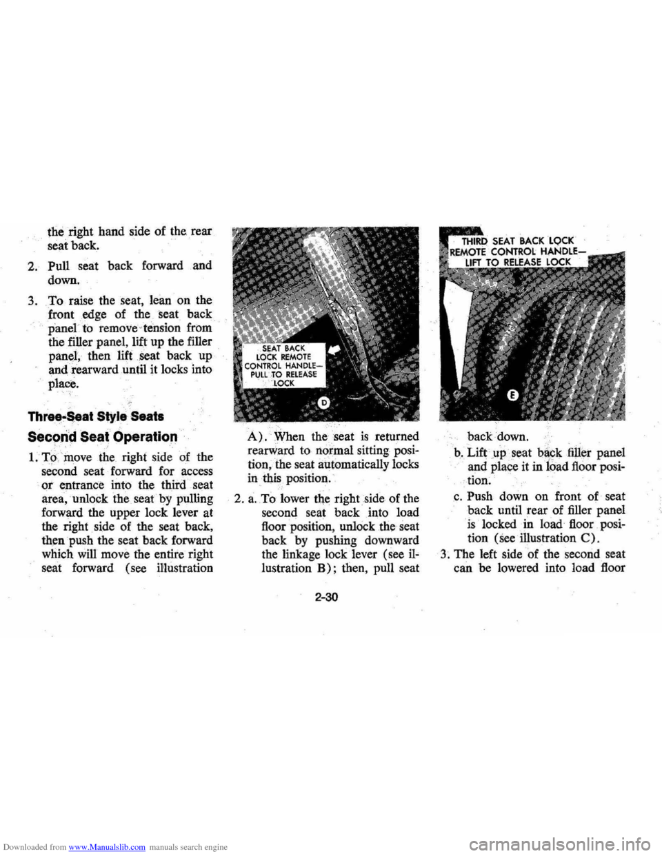
seat forward (see illustration
A). When the. seat is returned
rearward to normal sitting posi
tion,the seat automatically locks
in
this position.
2 .
a. To lower the right side of the
second seat back into load
floor position , unlock
the seat
back
by pushing downward
the linkage lock lever (see
iJ~
lustration B); then, pull seat
2-30
back down.
b .
Lift.up seat backfiUel' panel
and place it
in load floor posi
- tion.
,c . Push down on front of seat
back until rear of filler panel
is locked in load floor posi
tion
(See illustration C)_
3. The left side of the second seat
can be lowered into load floor
Page 45 of 102
Downloaded from www.Manualslib.com manuals search engine position fro1)1 either side of the
car
as follows:
a . From right side of car~wi~
right seat (one third seat)lfi
forward or load floor position,
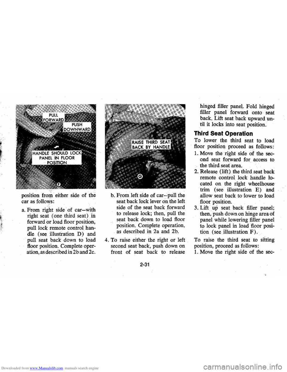
pilll lock remote control han
dle (see illustration
D) and
pull seat
baclcdownto load
floor position. Complete oper
ation , as described
in 2b and 2c.
b.From left side of car-:-pull the
seat back lock lever on the left
side of the seat back forward
to release lock;
then,. pull the
s eat back
down to load floor
PQsition. Complete operation,
as described in 2a and 2b.
4. To raise either the right or left
second seat back , push down on
front of seat back to release
2-31
hinged filler panel. Fold hinged
filler panel forward onto seat
back. Lift seat back upward
un~
til it locks into seat position.
Third Seat Operation
To lower the third Seat to load
floor position proceed
as follows:
1. Move the right side of the sec
ond seat forward for ·access to
. the third seafarea .
2. Release (lift) the third . seat back
remote control lock handle lo
cated on the right wheelhouse
trim (see illustration
E) and
allow seat back
to lower to load
floor position.
3. Lift up seat back filler panel;
then , push down on hinge area of
panel while lowering filler panel
to lock panel in load floor posi
tion (see mustration
F).
To raise the third seat to silting
position , proceed as follows:
1. Move the right side of the sec-
Page 46 of 102
Downloaded from www.Manualslib.com manuals search engine ond seat forward for access to
the third seat area.
2. Lift third seat back hinged filler
panel
rearward onto seat back,
then, grasp seat back handle and
lift seat
back. upward until it
locks
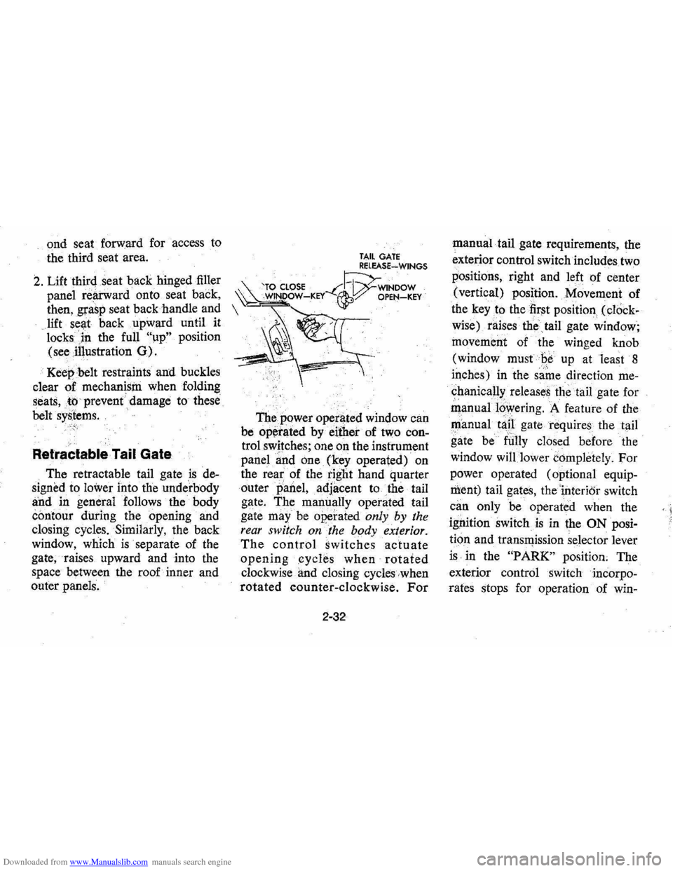
in the full "up" position
(see illustration
0).
Keep belt restraints and buckles
clear of mechanism when folding
seats,to prevent damage to these
belt
systems. C·>·i
Retractable Tail Gate
The retractable tail gate is de
signed to
lower into the underbody
and in general follows the body
contour during the opening and
closing cycles. Similarly, the back
window, which
is separate of the
gate, raises upward and into the
space between the roof inner and
outer panels.
TAIL GATE RELEASE~WINGS
'TO CLOSE --C~WINDOW ~ WINDOW-KEY ~:/ OPEN-KEY
The power operl)ted window can
be
op~rated by either of two con
trol switches; one on the instrument
panel
~nd one (key operated) on
the
rea~ of the tight hand quarter
outer
panel, adjacent to the tail
gate. The manually operated tail
gate
may" be operated only by the
rear switch on the body exterior.
The control switches actuate
openingcycle.s when rotated
clockwise and closing cycles when
rotated counter-clockwise. For
2-32
manual tail gate requirements, the
exterior control switch includes two
positions, right and left of center
(vertical) position. Movement of
the
key to the first position (cl()ck
wise) raises the
tail gate window;
movement of the winged knob
(window must
Be up at least 8
iqches) in the same direction me
chanical!>: releases the tail gate for
manual16wering. A feature of the
~anual tap gate requires the tail
gate be
fUlly closed before the
window
will lower completely. For
power operated (optional equip
ment) tail gates, thei,nterior switch
can only be operated when the
ignition switch
is in the ON posi
tion and transll)ission selector lever
is in the "PARK" position. The
exterior control switch incorpo
rates stops for operation of win-
< I