1974 Citroen CX height adjustment
[x] Cancel search: height adjustmentPage 236 of 394

Downloaded from www.Manualslib.com manuals search engine OPERATION No MA. 410-O : ( /,c
1
CHECKING AND ADJUSTING THE FRONT AXLE USING AN OPTICAL ALIGNMENT GAUGE
IMPORTANT The checks and adjustments described in this operation are carried out with a BEM-MULLER 665
JUNIOR kit
The sequence and
the procedure remain the same when carried out using another type of equipment. In that case,
take account of the instructions of the other kit I. PREPARING THE VEHICLE
cl
b
-.
I t 1. Check tyre pressures.
2. Rending off vehicle heights in normal running position
c,)
b ) .\I ri,f,,,g /he ,w.s;‘;o,,
Measure the distance Ll when vehicle is at II height of 165 mm at the front and the distance L2 when the
vehicle is at CL height of 165 mm at the front and the distance L2 when the vehicle is at a height of 215 mm
at the rear ( .Snloo,, I vhi~/r,s 1 or 228 mm I I:.s/o/c / chirlr,. 1. Note values Ll and L2 which will simplify the
following checks. 3. Check that the lengths of visible thread on left and right trackrods are equal to within approximately 2 mm
r .Mm,,tnl 51<,<,r;r,,q I <,hirl?s WI). )
r
Rh‘td Ii. POSITIONING THE VEHIOLE
7
-1 1. Prepare and position the vehicle :
a) Lock turntables using pins ( 1 ).
Move the vehicle forward in a straight
line in order 10 plnce ironl r,hccls iv
Ihe
rwrtw o/’ fhC /,,n,tab/~s.
IMPORTANT If the turntables ore not flush
with the ground ( when not set in the ground ),
place a compensating chock, of identical
thickness to that of the turntables, under
each rear wheel.
b 1 Apply the hondbrake.
Page 285 of 394

Downloaded from www.Manualslib.com manuals search engine OPERATION No MA. 453=0 : Ch J k’ ( c zng and adjjusfing thr hydraulk brake rontrol Op. MA. 453-O 3
III. CHECKING BRAKE PEDAL FREE PLAY
1 st Fitting 2nd Fitting
1 5 111 (I I /‘)7-t __t i%
+ 1. Turn screw ( 1 ) to obtain a clearance of
s
E
(( J )) ~~ 0.05 to 3 mm
-ii Tighten lock-nut ( 2 ).
2 2. Ch k’ ec Ing operation of brake pedal :
a) Release pressure in system.
Set manual height control to /or! /~~.s\‘itio~/
Slacken pressure regulator bleed screw.
( I/ Ill<, I <~/liClC~ is /ill1 rl i, ill, N I~tYlk~~ n~-rllrlll,Inlo,~. nc/un/1 II?<, /I< r/al.
hnke nr c111uu/n/0,. ).
b) Depress pedal three or four times to move the control slide valve to the end of its stroke, and ensure that
pedal returns freely to its stop.
There should be no variation of clearance o J )) as initially set.
Tighten pressure regulator bleed screw.
IV. ADJUSTING THE STOPLAMP SWITCH
1.
Check adjustment of free play on brake pedal ( see above ).
2. Adiusting the stoplamp
The stoplamps must light as soon as the pedal contacts the brake valve.
Bend support plate u a )) of the switch in order to achieve this condition.
Page 358 of 394

Downloaded from www.Manualslib.com manuals search engine OPERATION No MA. 540-O : (hcrking and diusfing the hradlmnps. Op. MA. 540.0 1 ADJUSTING THE HEADLAMPS USING A << REGLOSCOPE >> OR I< REGLOLUX n TYPE APPARATUS
I. CONDITIONS FOR ADJUSTMENT
With the vehicle empty and in running order :
a) Ensure that the tyre ore correctly inflated
and heights correctly adjusted.
Place vehicle on CI flat level surface.
Run the engine at idling speed and set manual.
height control to normal running position.
1 Place the instrument on the same level as that
of the vehicle and opposite the headlamp to be
adjusted. 2. ADJUSTMENT
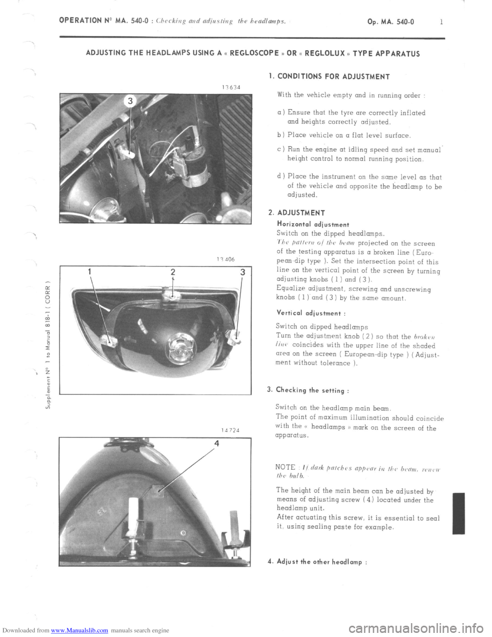
Horizontal adiustment
Switch on the dipped headlamps.
711~ pn,lcrv 01 111~ lwflrn projected on the screen
of the testing apparatus is a broken line (Euro
pea-dip type 1. Set the intersection point of this
line on the vertical point of the screen by turning
adjusting knobs ( 1 ) and (3 ).
Equalize adjustment, screwing and unscrewing
knobs (
1) and (3 1 by the same amount.
Vertical .dius+ment :
Switch on dipped headlamps
Turn the adjustment knob (2) so that the hrokr’n
lirw coincides with the upper line of the shaded
cwea on the screen ( European-dip type ) (Adjust-
ment without tolerance ). 3. Checking the setting :
Switch on the headlamp main beam.
The point of maximum illumination should coincide
with the (’ headlamps 3) mark on the screen of the
apparatus.
The height of the main beam can be adjusted by
means of adjusting screw (4 1 located under the
headlamp unit.
After actuating this screw, it is essential to seal
it, using seoling paste far example. 4. Adiust the other headlamp :
Page 384 of 394

Downloaded from www.Manualslib.com manuals search engine OPERATION No MA. 841-O : Adjusting fh~ doors Op. MA. 841-O 1 I. ADJUSTING A FRONT DOOR
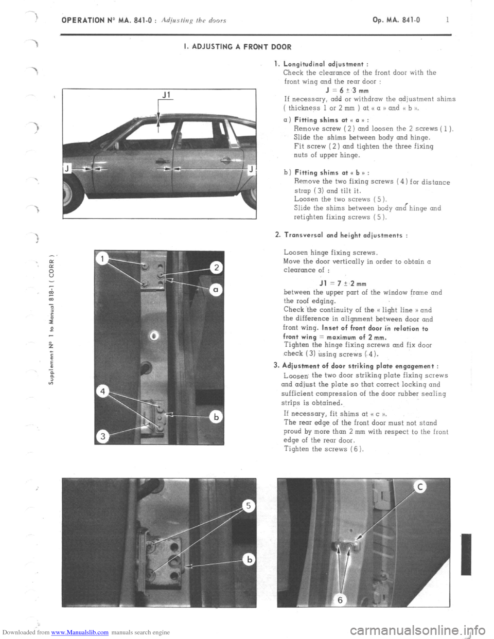
1. Longitudinal adiustment :
Check
the clearance of the front door with the
front wing and the rear door : J=6+_3mm
If necessary. add or withdraw the adjustment shims
( thickness 1 or 2 mm ) at <( a 1) and << b to_ a) Fitting shims at SC a u :
Remove screw (2) and loosen the 2 screws ( 1).
Slide the shims between hody and hinge.
Fit screw (2) and tighten the three fixing
nuts of upper hinge.
b) Fitting shims at <, b n :
Remove the two fixing screws (4) for distance
strop (3) and tilt it.
Loosen the two screws (5 ).
Slide the shims between body &hinge and
retighten fixing screws (5 ). 2. Transversal and height adjustments :
Loosen hinge fixing screws.
Move the door vertically in order to obtain a
clearance of : Jl = 7 +‘2mm
between the upper port of the window frame and
the roof edging.
Check ‘the continuity of the a light line 1) and
the difference in alignment between door and
front wing. Inset of front door in relation to
front wing = maximum of 2 mm.
Tighten the hinge fixing SCWNS and fix door
check (3) using screws (“4). 3. Adjustment of door striking plate engagement :
Loosen. the two door striking plate fixing screws
and adjust the plate so that correct locking and
sufficient compression of the door rubber sealing
strips is obtained.
If necessary, fit shims at (cc )P.
The rear edge of the front door must not stand
proud by more than 2 mm with respect to the front
edge of the rear door.
Tighten the screws (6 ).
Page 385 of 394

Downloaded from www.Manualslib.com manuals search engine 2 OPERATION NO MA. 841-O : Adjmfing /he o’r,ors
II. ADJUSTING A REAR DOOR
1. Longitudinal adjustment :
Check the clearonce of the rear door with the
rear wing and with the front door :
J =6+~3mm
If necessary, fit Suitable shims ( of thickness 1 or
2 mm ) at points (( a N and (( b )).
a) Fitting shims at point II a * :
Remove screw ( 1) ond loosen screws (2).
Slide in at point I< a D under hinge the shim or
shims required.
Fix scr&v (2 ).and tighten the three hinge
fixing screws.
b)
Fitting shims at point e b u :
Remove distance strop fixing screws and pivot
it, around its axis.
Loosen the two hinge fixing screws (4).
Slide shims under hinge at point <, b >j.
Re-tighten fixing screws (4 1.
2. Transversal and height adjustments :
Check clearance between upper edge of window
frmne and
edqe of roof :
Jl =7+~2mm
Check also continuity of the G light line x
and the recess
of the rear door in relation ta
the front door : 2 mm max.
Loosen upper and lower hinge fixing screws.
Adjust door to obtain positioning (IS above.
Tighten fixing screws of these hinges.
Secure distance strap by its two screws (3)
3. Adjustment of striking plate engagement :
Loosen striking plate fixing screws (3) and adjust so as
to obtain correct locking of door and sufficient
compression of the rubber sealing strips.
If necessary, fit adjustment spacers at point o c u.
Check recess
of rear wing in relation ta rear
dwr : 2 mm max.
4: Position window-winder handle to obtain an angle.
of W = approximately 30’ when the window is
closed.
Page 386 of 394

Downloaded from www.Manualslib.com manuals search engine OPERATION No MA. 844-O : Ad;,/<~lics /be hoot /ic/ Op. MA. 844-O 1
ADJUSTING THE BOOT LID
1. Tronsversol and longitudinal odiustment :
Slacken SCEWS ; 1 ) to obtain (I correct cenirolized
position of the boot lid.
J , 6 ! :‘” mm
with CL difference betwrrn the two meosurrments
of no more than 2 mm. and a clearance ot 18 a 1, ofOi3mm.
Tighten SCIWS ( 1). 2. Height odiustment :
Remove screws ( 2 ) and the sidr trim of rwr
window i vu vi/h~‘r ciriv ,.
Slacken screws ( 3 1 and adjust boot lid in order
to obtain
at I, b a/ a cle.r.nce of 0 ! 3 mm,
clraranc~ brtween war
window rmd boot lid : JZ-6.514mm
clearancr brtwrrn boot lid and rwr bumper
10 rmn (by way of indication)
Tighten screws ( 3 ).
Fix trim and trim fixing screws ( 2 ) /DU c iih~ ) \i&).
3. Adjustment of lock:
Loosen screws ( 4 i and mokr vertical odjustmrnt
to lock in ordrr to obtain correct engagement with
striking plate. 4. Adiustment of striking plate :
Loos-n screw ( 5) and adjust plate so that boot
lid bears odrquatrly on sealing rubbe‘s
Page 387 of 394

Downloaded from www.Manualslib.com manuals search engine OPERATION No MA. 852-O : Adius/ir,y I/><, bo,,r,r/ Op. MA. 852-O 1
~.
I. ADJUSTING THE BONNET
I. Height adjustment :
Remove screws (2) securing bonnet hinge to the
body.
Position suitable shims at u a )) to ensure the
recess of bonnet in relation to front wings : R = 2 mm max.
Fit and tighten screws (2 ). 2. Transversal and longitudinal adjustment :
Loosen hinge fixing screws ( 1 ) on bonnet
Adjust them in order to obtain a clearance
between bonnet and wings : J=6
+ 2.5
-1 mm
- with (I maximum difference of 2.5 mm between
left and right-hand sides and a maximum diffe-
rence in level of 2 mm,
- adjust also to obtain clearance between front
edge of wings and bonnet : E = 0 it3 mm
3. Adjusting the striking plate :
Loosen screws ( 3 )
Centre striking plate in relation to lock.
Tiqhten screws ( 3 ). 4. Adjusting the safety catch :
Loosen screw5 (4 1.
Adjust safety catch so that :
With bonnet resting on catch, the latter must engage
under weight of bonnet alone.
Tighten screws (4 ). 5. Adjusting the lock and lock control cable :
Remove scravs (6 ) and (7 ) and protective
plate (5).
Loosen screws (8) and adjust height of lock
in order to ensure, recess R, at the front.
Tension lock control cable by screwing nut (9 )
to eliminate any clearance on bonnet opening
leV%. Bonnet should lock correctly when dropped
from (I height of 250 mm.