Page 216 of 394
Downloaded from www.Manualslib.com manuals search engine BRAKE ACCUMULATOR
1 I’r~rc~(,r-s!(,(,riri~ I cbic-lcc5 J
HP
To brake valve
--
Front brakes supply Supply :
- steering governor
- safety valve CHARACTERISTICS
Brake accumulator :
- Capacity .._._._.._.._.___._____._._._..__........ _._____ _......._._.___._ _____..____.___ ___._._._._._._. 0 400 litre ( C. 70 pts )
- Identification mark on filler plug ,...........
62
- Calibration pressure f /or rhc,c-kir/~ J 62 _ 3z bars ( 899 1 dTd psi ) SPECIAL FEATURES
Tightening torque :
- Accumulator. onto its mounting .,..... .., .._.. .._.. .._....._._._. 3 daNm ( 21 l/ 2 ft.lb )
Page 218 of 394
Downloaded from www.Manualslib.com manuals search engine 10 OPERATION No MA. 390-00 : Churarteristics and special features oi the source
and reserlv oj pressure - Hydraulic system HYDRAULIC SYSTEM SUPPLY DIAGRAMS
1. Supply diagram :
a) Manual steering vehicles :
HP supply
1
Safety ~ Front suspension
va1ve \Rear suspension valve /
1 Rear brakes
Front’ brakes
b ) Power stesritzg vehicles :
HP supply
I
- Brake accumulator - Brake
valve -S
upply to front brakes
I
3-way T ’ Supply to steering governor
Safety talve yw Front suspension
A Rear suspension - y”,;“,“,’ L supp1y to
rear brakes
Steeiing
( Supply to control slide valtv a?zd operating cylirzder J
Page 219 of 394
Downloaded from www.Manualslib.com manuals search engine HYDRAULIC SYSTEM SUP.PLY DIAGRAMS
Source of pressure
I
h-Front suspension
Safety “‘lve ; Rear suspension
I
I Brake valve
i :ure limiter-
1
Front brakes Rear brakes
Source of pressure
I
Brake cccumulator
Supply to
I-way wion - steering governor
/Front
Safety va1ve- Rear suspension
I
Steering ( supply to slide-valve and operating cylinder )
Page 220 of 394
Downloaded from www.Manualslib.com manuals search engine Source of pressure
Safety ialveYFront suspension
t
L Rear suspension
I I
Brake valve w Brake pressure limiter w Rear brakes
I t
Front ‘brakes
Source of pressure
I
Brake accumulator
I
3-way union F Brake valve w Front brakes
Supply to steering governor
Safety I
va1ve y Rear suspension
I
Steering ( supply to slide-valve and operating cylinder )
Page 268 of 394
Downloaded from www.Manualslib.com manuals search engine d
m
.-
0
2
f Op. MA. 440-00
7 -
b) Steering governor :
It is situated on the front subframe, and mechanically driven ( cable ) by the final drive unit in the gearbox.
Ei A ”
VEHICLE STOPPED (engine running)
L.44-14b
I/ /II I Pressure
IL Towards
HP cam cylinder
VEHICLE IN MOTION
* Slide-valve A is linked in linear motion to lever B
- Fly-weights C, which rotate ( and fly towards under the effect of centrifugal force ) cause lever B to tilt.
=
L'nrioblc, position of slide-valve A, allows the pressure exerted on the cam cylinder piston to be varied.
NOTE In order to make possible the powered return function. the steerinq governor supplies a pressure
of 20 i-15 bars ( 290 +173 psi ) when the vehicle is stopped f 11
i/F /hc cwgir/e wt/t~iv.g i.
I
POWERED RETURN
The powered return is a combination of the two preceding functions, the variable feel function controlling the
power-operation function.
Page 269 of 394

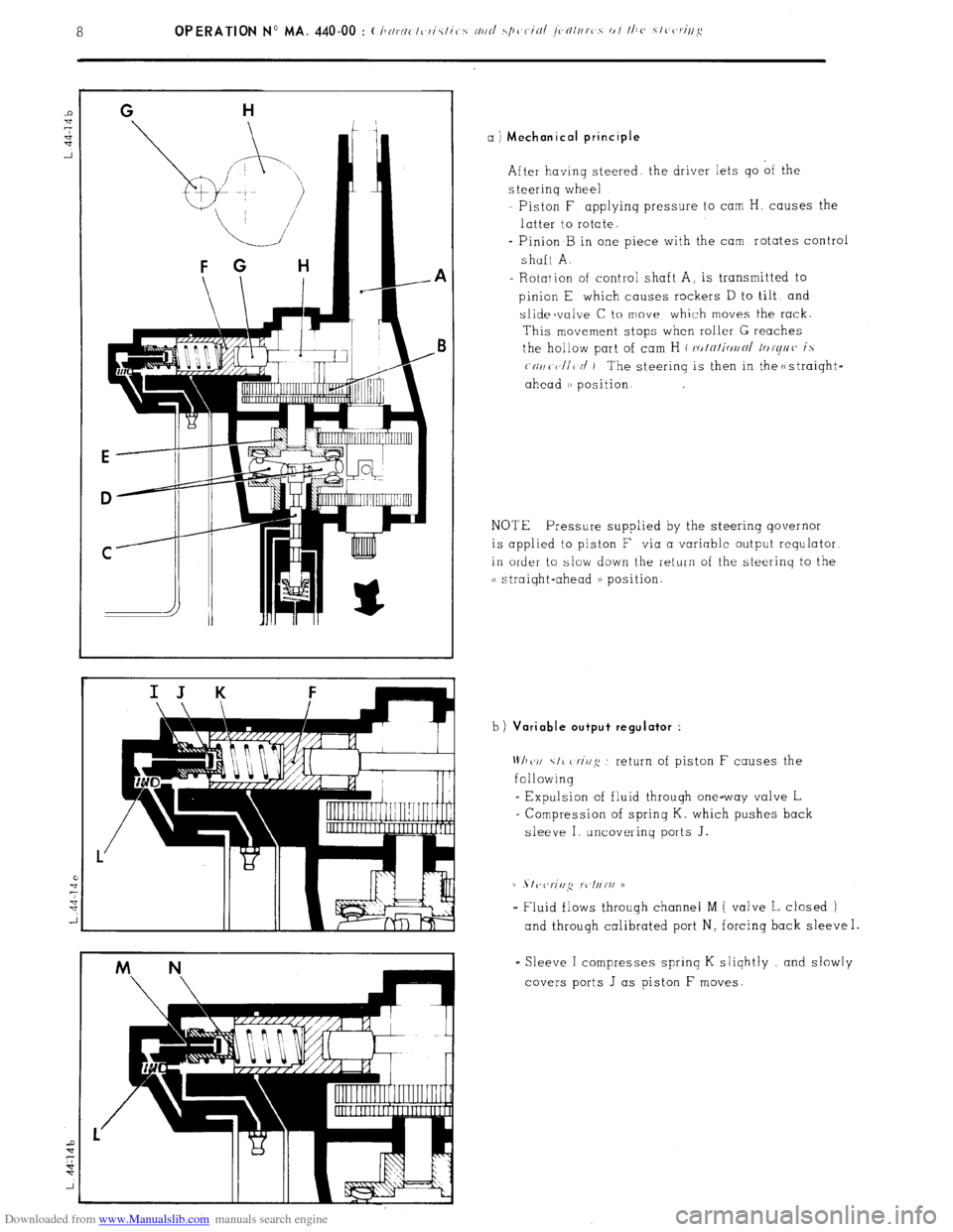
Downloaded from www.Manualslib.com manuals search engine a ) Mechanical principle
After having steered the driver lets go of the
s teerinq wheel
Piston F applyinq pressure to cam H, causes the
latter to rotate.
- Pinion B in one piece with the cam rotates control
shaft A.
- Rotation of control shaft A, is transmitted to
pinion E which causes rockers D to tilt and
slidecvalve C to move which moves the rack.
This movement stops when roller G reaches
the hollow part of cam H ( ro/~/i<,//~/ /or(//((’ is
(-(II/( V/I< N’ ) The steerinq is then in the c
ahead i) position.
NOTE Pressure supplied by the steering governor
is applied to piston F via a variable output requlator
in order to slow down the return of the steerinq to the
v straiqht-ahead a) position.
b)
Variable output regulator :
Wh(‘I/ \I< criq .’ return of piston F causes the
following
_ Expulsion of fluid through one-way valve L
= Compression of sprinq K. which pushes back
sleeve I uncovering ports J.
(1 . I vl,riil,q rc l//rI/ D
- Fluid flows throuqh channel M ( valve L closed )
and through calibrated port N, forcing back sleeve I.
= Sleeve I compresses sprinq K sliqhtly and slowly
covers ports J as piston F moves.
Page 271 of 394
Downloaded from www.Manualslib.com manuals search engine 10 OPERATION No MA. 440-00 : (:hnrnct(,rictic.,s nttd .s/)cjcitil jcntr/rc,.s 01 the stc,c,rirtg CROSS-SECTION OF STEERING GOVERNOR
L.
44-16