1973 FIAT 500 Fiat 500 R
[x] Cancel search: Fiat 500 RPage 33 of 128

FIG 2 : 9 Weber 26.IMB carburetter cover components
Key toFig 2 : 9 1 Float 2 Carburetter cover 3 Float pivot 4 Needle valve gasket 5 , 6 Needle valve seat and needle valve
7 Cover gasket 8 Filter strainer 9 Gasket 10 Filter inspection plug
Carburetter cleaning:
To thoroughly clean the carburetter proceed as follows:
1 Passages. All fuel passages have a diameter that is
specially calibrated to ensure best operating conditions.
It is therefore essential that any dirt or scale that has
been deposited by petrol must be removed. Thoroughly
clean with petrol and blow dry using a compressed air
jet directed through all the passages in the castings. It is
essential that no drills or other metal objects be passed
through the jets or the passages otherwise these could
alter the finely calibrated diameters.
2 Calibrated parts. Idling and main jet holders, and the
relevant bayonet coupled jets are easily removed by
using a suitably sized wrench or screwdriver. To clean
the different calibrated parts, thoroughly wash in petrol
and blow dry using a compressed air jet. Do not use any
fine drills or metallic points as these may alter the fine
calibration of the orifices. Should it be necessary to dis-
mantle the carburetter adjustment components for
inspection always ensure that after reassembly of the
parts that they are seated correctly to avoid possible
operating troubles in the future.
3 Filter. To clean the filter unscrew and remove its plug
10 (see FIG 2 : 9) located on the top of the carburetter
cover and then gently ease o u t t h e filter. Wash the filter
carefully in petrol, also ensure that the filter seat is clean
and then blow dry using a compressed air jet.
2:7 Modifications
The Weber 26.IM B carburetter has undergone a number
of minor changes during the development of the Fiat 500
models, but no changes in servicing procedure are made
necessary. Jet sizes and other calibrations are detailed
in Technical Data.
From 1970, the mounting flange of the carburetter is
slightly modified to incorporate a different mixture
adjustment screw, as shown in FIG 2:11.
40
Throttle valve components:
The throttle valve shaft should rotate freely in its guides
and this should be checked when the engine is at its
normal operating temperature. Any excessive clearance
caused by wear or the throttle valve butterfly distorted are
liable to cause irregular engine operation which will be
more pronounced at idling speed. Should the above con-
ditions be evident then the throttle valve butterfly and the
shaft assembly together with its sealing rings must be
renewed.
FIG 2:10 Jets, jet holders and choke valve
Key to Fig 2:10 1 Choke valve 2 Spring
3 Spring retainer and guide 4 Lock ring 5 Air bleed jet
6 Emulsion well 7 Choke jet 8 Idling jet holder and jet
9 Main jet holder and jet 10 Main jet holder gasket
Page 42 of 128

a n 0—20 v o ltmeter. If the circuit is in order the meter
should read approximately 12-volts.
3 Battery to fuse box terminal 30. Connect the volt-
meter between the terminal 30 and earth. No reading
indicates a faulty cable or loose connection.
4 Fuse box. Connect the voltmeter between the other
auxiliary terminal 30 and earth. No reading indicates a
broken or loose connection.
5 Fuse box auxiliary terminal 30 to terminal
number 30 on ignition switch. Connect the meter
between terminal number 30 on the ignition switch
and earth. No reading indicates a damaged cable or
loose connection.
6 Ignition switch. Connect the meter between termi-
nal 15/54 and earth. Switch onto the ignition position,
when no reading indicates a fault in the switch.
7 Ignition switch to low-tension cable connection
on the coil (blue cable). Connect the meter
between ignition coil terminal (blue cable) and earth.
No reading indicates a damaged cable or loose con-
nection.
8 Ignition coil. Disconnect the black low-tension cable
connecting the coil to the distributor side terminal at
the coil and connect the meter between this terminal
and earth. No reading indicates a fault in the primary
winding of the coil and a replacement coil must be
fitted. If the reading is correct remake the connections
to the coil.
9 Ignition coil to distributor. Disconnect the thin
black low-tension cable at the side of the distributor
and connect the meter between the end of this cable
and earth. No reading indicates a damaged cable or
loose connections.
10 Contact breaker and capacitor. Connect the
meter across the contact breaker points. No reading
indicates a faulty capacitor.
Capacitor:
The best method of testing a capacitor (condenser) is
by substitution. Disconnect the original capacitor and
connect a new one between the low-tension terminal on
the side of the distributor and earth.
If a new capacitor is needed, fit a new one complete
w i t h bracket, but if necessary unsolder the original bracket
and solder it onto the new capacitor using as little heat as
possible. Capacitor capacity is .15-.20 microfarads.
3 : 5 Removing and dismantling distributor (sedan
and sports)
To remove the distributor proceed as follows:
1 Rotate the engine slowly until the distributor rotor arm
is opposite the brass segment in the distributor cap
connected to No. 1 plug lead. This will provide a datum
for replacement.
2 Disconnect the cable from the low-tension terminal on
the side of the distributor body. Mark position of distri-
butor on support. Release the distributor retaining nut
and washer from the underside of the top flange of the
distributor support and carefully lift away the dis-
tributor.
3 Pull off the rotor arm. Remove the insulated terminal
assembly from the side of distributor body. Release the
contact breaker carrier plate retaining screws and con-
denser flange screw from the outside of the distributor
F50049 body. Carefully lift out the contact breaker plate
assembly.
4 Before further dismantling note the relative positions of
the driving dog and the rotor arm driving slot at the top
of the distributor cam spindle. The driving dog is offset
and can only engage its driving spindle in one position.
Then when the cam assembly is fitted to the centrifugal
weights during reassembly the timing is not 180 deg.
out.
5 Take out the cam lubrication felt pad recessed in the
rotor arm housing on the end of the cam spindle.
Remove the retaining screw, carefully disengage the
springs and lift out the cam spindle. It should be noted
that there is a small retaining ball and spring located in a
drilling nearly at the top of the drive shaft spindle.
Carefully lift away the weights.
6 Thoroughly clean all parts and inspect for excessive
wear. The distributor cap must not be cracked or show
signs of tracking. The cap terminals, rotor and contact
breaker points can be cleaned with a very fine file.
Emerypaper must not be used. If the clearance between
the rotor and distributor cap segments exceeds .0118
inch both the rotor and distributor cap must be replaced.
Inspect the contact breaker arm rubbing block for exces-
sive wear and also the points for wear so that if the gap
exceeds the last setting limit of .0209 inch and adjust-
ment through the stationary contact carrier screw is no
longer possible (see FIG 3 : 2) , the contact breaker set
must be renewed.
If the distributor drive shaft side or vertical movement is
excessive the distributor must be renewed.
Weak centri-
fugal weight springs or damaged weights must be
renewed using original Fiat spares otherwise the auto-
matic ignition advance characteristics could be altered.
FIG 3 : 3 Ignition distributor in place on engine SPARK PLUG CABLES
IGNITION COIL CABLE!
DISTRIBUTOR CAP
DISTRIBUTOR BODY
GROUND CABLE
CONDENSER
DISTRIBUTOR SHAFT
LUBRICATION FITTING
DISTRIBUTORSUPPORT-TO--CRANKCASE NUT
[MOUNTING SCREWDISTRIBUTOR
DISTRIBUTOR SUPPORT
Page 43 of 128

FIG 3 : 4 Use of fixture Ap.5030/1 to check ignition
timing
Reassembly is the reverse procedure to dismantling but
the following points should be noted:
1 Lubricate the parts of the centrifugal advance mecha-
nism, the drive spindle and the part of the shaft which
accepts the cam w i t h Fiat VS oil.
2 Ensure that upon reassembly the slot in the rotor arm
housing matches the distributor driving dog. Lubricate
the felt pad in the rotor arm housing.
3 Fit the distributor back onto its support gently rotating
the rotor arm so that the drive dog engages w i t h the
drive shaft mating flange. Provided the crankshaft has
not been turned the rotor arm should finish up pointing
to No. 1 cylinder segment in the distributor cap. Tighten
the distributor retaining nut, refit the distributor cap and
leads to the spark plugs and the LT lead to distributor
body terminal.
4 Add a few drops of oil to the distributor shaft lubrication
fitting (see FIG 3:3).
3 : 6 Removing and dismantling distributor
(station wagon)
The distributor is located towards the top rear of t h e
engine and is bolted direct onto the crankcase rear cover as
shown in FIG 1 : 2 . It is driven direct by a gear in mesh w i t h
a corresponding gear on the camshaft. The basic design of
the distributor is the same as that for the sedan and sports
engine, except that the distributor cap has been redesigned,
there is a gear instead of the dog
drive and no distributor
support. To remove and dismantle the distributor proceed
as previously described taking great care about marking
the location of the distributor to rear cover and rotating
the engine until No. 1 cylinder is on compression. This will
ensure that reassembly is straightforward without loss of
ignition timing.
503:7 Timing the ignition
It is necessary to retime the ignition should the distribu-
tor shaft or camshaft have been removed. To retime the
ignition proceed as follows:
1 On the timing sprocket cover fit Fiat tool AP.5030/1 as
shown in FIG 3 : 4. Ensure No. 1 cylinder is on the
compression stroke with both valves closed. Rotate the
crankshaft until the mark on the centrifugal filter cover
lines up w i t h the 10° mark on the fixture. This setting
corresponds to a 10° static advance BTDC.
2 Check t h a t the points gap is correctly set between
.018 and .020 inch. Turn the distributor shaft until the
rotor points in the direction of No. 1 segment in the
cap and the points are just opening.
3 Without disturbing the distributor shaft, insert the lower
coupling on its toothed end, install the support and
tighten the locknut. Secure the distributor to the sup-
port using the mounting screw.
To check that the distributor is properly timed to the
engine and the centrifugal automatic advance is operating
correctly giving a
total advance of 18° to 28° respectively
proceed as follows:
1 Connect Fiat timing tester AP.5030 with a 220-volt-
single-phase power outlet fitted with a good earth
connection. It is important that the tester is earthed
before it is allowed to operate. Also ensure that the
tester earth terminal is connected to a bare metal part
of the vehicle.
2 Remove No. 1 spark plug lead, insert the strobe light
adapter and reconnect the spark plug lead. Using a
piece of white chalk mark the TDC position on the
centrifugal filter cover.
3 Start the engine and aim the strobe light beam towards
the chalk mark drawn on the centrifugal filter cover.
With the engine running slowly the mark on the centri-
fugal cover must correspond wi th the first white line
on the fixture (10°). Slowly increase the speed of the
engine so operating the automatic advance and the
chalk mark should move counterclockwise until at
maximum speed it reaches the second white mark on
the fixture.
It should be noted that the ignition timing for the model
500 sports engine the static advance is 10°, an automatic
advance of 12° giving a total advance at maximum engine
speed of 2 2 ° .
Should Fiat fixture AP.5030/1 not be available the
advance position may be set as follows:
1 Turn over the
engine until No. 1 piston is on the com-
pression stroke w i t h both valves closed.
2 Rotate the crankshaft clockwise until the reference
mark cast on the centrifugal filter cover is set .5118 to
.5512 inch ahead of the arrow cast on the timing
sprocket cover. This will give a static advance setting
of 10° BTDC.
3 Proceed as directed for ignition distributor timing and
mounting described earlier in this section.
3 : 8 Sparking plugs
The sparking plugs must be regularly inspected, cleaned
and the electrode gap adjusted to a gap of .019 to .023
inch.
The inspection of the deposits on the electrodes is par-
ticularly useful because the colour and type of deposit
Page 46 of 128

CHAPTER 4
THE COOLING SYSTEM
4:1
4:2
4:3Description
Air outlet thermostat and shutter
Tension adjustment4:4
4:5
4:6Heating system safety device
Maintenance
Fault diagnosis
4:1Description
Sedan:
A l l the Fiat new 500 models covered by this manual are
aircooled by the forced air circulation system from a
centrifugal blower which is mounted on the generator
output shaft. The blower fan has fourteen vanes which are
arranged at various angles to reduce operating noise
during high-speed operation. A specially designed
cowling as shown in FIGS 4 : 1 and 4:2 conveys the air
from the blower and distributes it to the various parts of
the exterior of the engine.
The main components of the air cooling system are as
follows:
1 Air intake compartment at the rear end of t h e body.
2 An elbow pipe for the admittance of incoming air.
3 A flexible air pipe connecting the elbow pipe to the
conveyor.
4 A spiral air conveyor which contains the centrifugal fan.
5 Distribution ducting for directing the air flow to various
parts of the engine.
6 A bellows type thermostat is fitted to the cowling which
operates a butterfly shutter controlling the air outlet
from the engine which ensures control of the engine
operating temperature.
F50053 When the shutter is in the open position, engine heated
air is allowed to disperse to the outside of the engine
cowling. With the shutter in its closed position, the air is
recirculated in the engine cowling so ensuring a quick
engine warm-up period.
It should be noted that by operating the heater lever
which is located on the centre tunnel at the rear seat,
warmed air flowing out from the engine cowling is passed
to the inside of the car for heating and demisting purposes.
Station wagon:
Refer to FIG 4 : 2 where it will be seen that as the engine
is located on its side underneath the luggage compartment
floor the ducting has been modified and the air intakes are
located at the rear of the side windows. A linear blower is
housed in the engine baffles and cowling and is attached
to the drive end of the generator.
The thermostat 'C' (see FIG 4 : 2) is located on the
righthand side of the engine cowling and should start
opening the engine heated air outlet shutter ' D ' when the
temperature of the air rises to 1 7 8 - 1 8 5 ° F and the shutter
should be wide open when the air is at a temperature of
196-207°F.
Page 53 of 128
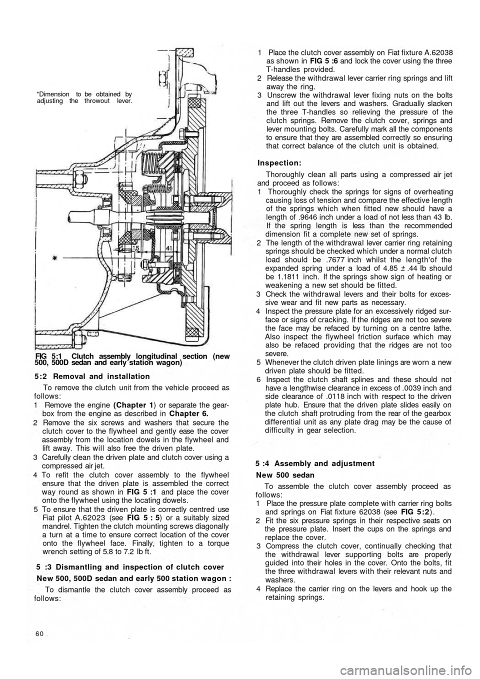
*Dimension to be obtained by
adjusting the throwout lever.
FIG 5:1 Clutch assembly longitudinal section (new
500, 500D sedan and early station wagon)
5 : 2 Removal and installation
To remove the clutch unit from the vehicle proceed as
follows:
1 Remove the engine (Chapter 1) or separate the gear-
box from the engine as described in Chapter 6.
2 Remove the six screws and washers that secure the
clutch cover to the flywheel and gently ease the cover
assembly from the location dowels in the flywheel and
lift away. This will also free the driven plate.
3 Carefully clean the driven plate and clutch cover using a
compressed air jet.
4 To refit the clutch cover assembly to the flywheel
ensure that the driven plate is assembled the correct
way round as shown in FIG 5 :1 and place the cover
onto the flywheel using the locating dowels.
5 To ensure that the driven plate is correctly centred use
Fiat pilot A.62023 (see FIG 5 : 5) or a suitably sized
mandrel. Tighten the clutch mounting screws diagonally
a turn at a time to ensure correct location of the cover
onto the flywheel face. Finally, tighten to a torque
wrench setting of 5.8 to 7.2 Ib ft.
5 :3 Dismantling and inspection of clutch cover
New 500, 500D sedan and early 500 station wagon :
To dismantle the clutch cover assembly proceed as
follows:
60
To assemble the clutch cover assembly proceed as
follows:
1 Place the pressure plate complete with carrier ring bolts
and springs on Fiat fixture 62038 (see FIG 5 : 2).
2 Fit the six pressure springs in their respective seats on
the pressure plate. Insert the cups on the springs and
replace the cover.
3 Compress the clutch cover, continually checking that
the withdrawal lever supporting bolts are properly
guided into their holes in the cover. Onto the bolts, fit
the three withdrawal levers w i t h their relevant nuts and
washers.
4 Replace the carrier ring on the levers and hook up the
retaining springs. 5 :4 Assembly and adjustment
N e w 500 sedan1 Place the clutch cover assembly on Fiat fixture A.62038
as shown in FIG 5 :6 and lock the cover using the three
T-handles provided.
2 Release the w i thdrawal lever carrier ring springs and lift
away the ring.
3 Unscrew the withdrawal lever fixing nuts on the bolts
and lift out the levers and washers. Gradually slacken
the three T-handles so relieving the pressure of the
clutch springs. Remove the clutch cover, springs and
lever mounting bolts. Carefully mark all the components
to ensure that they are assembled correctly so ensuring
that correct balance of the clutch unit is obtained.
Inspection:
Thoroughly clean all parts using a compressed air jet
and proceed as follows:
1 Thoroughly check the springs for signs of overheating
causing loss of tension and compare the effective length
of the springs which when fitted new should have a
length of .9646 inch under a load of not less than 43 Ib.
If the spring length is less t h a n t h e recommended
dimension fit a complete new set of springs.
2 The length of the withdrawal lever carrier ring retaining
springs should be checked which under a normal clutch
load should be .7677 inch whilst the length'of the
expanded spring under a load of 4.85 ± .44 Ib should
be 1.1811 inch. If the springs show sign of heating or
weakening a new set should be fitted.
3 Check the withdrawa l levers and their bolts for exces-
sive wear and fit new parts as necessary.
4 Inspect the pressure plate for an excessively ridged sur-
face or signs of cracking. If the ridges are not too severe
the face may be refaced by turning on a centre lathe.
Also inspect the flywheel friction surface which may
also be refaced providing that the ridges are not too
severe.
5 Whenever the clutch driven plate linings are worn a new
driven plate should be fitted.
6 Inspect the clutch shaft splines and these should not
have a lengthwise clearance in excess of .0039 inch and
side clearance of .0118 inch w i t h respect to the driven
plate hub. Ensure that the driven plate slides easily on
the clutch shaft protruding from the rear of the gearbox
differential unit as any plate drag may be the cause of
d i f f i c u l t y in gear selection.
Page 54 of 128
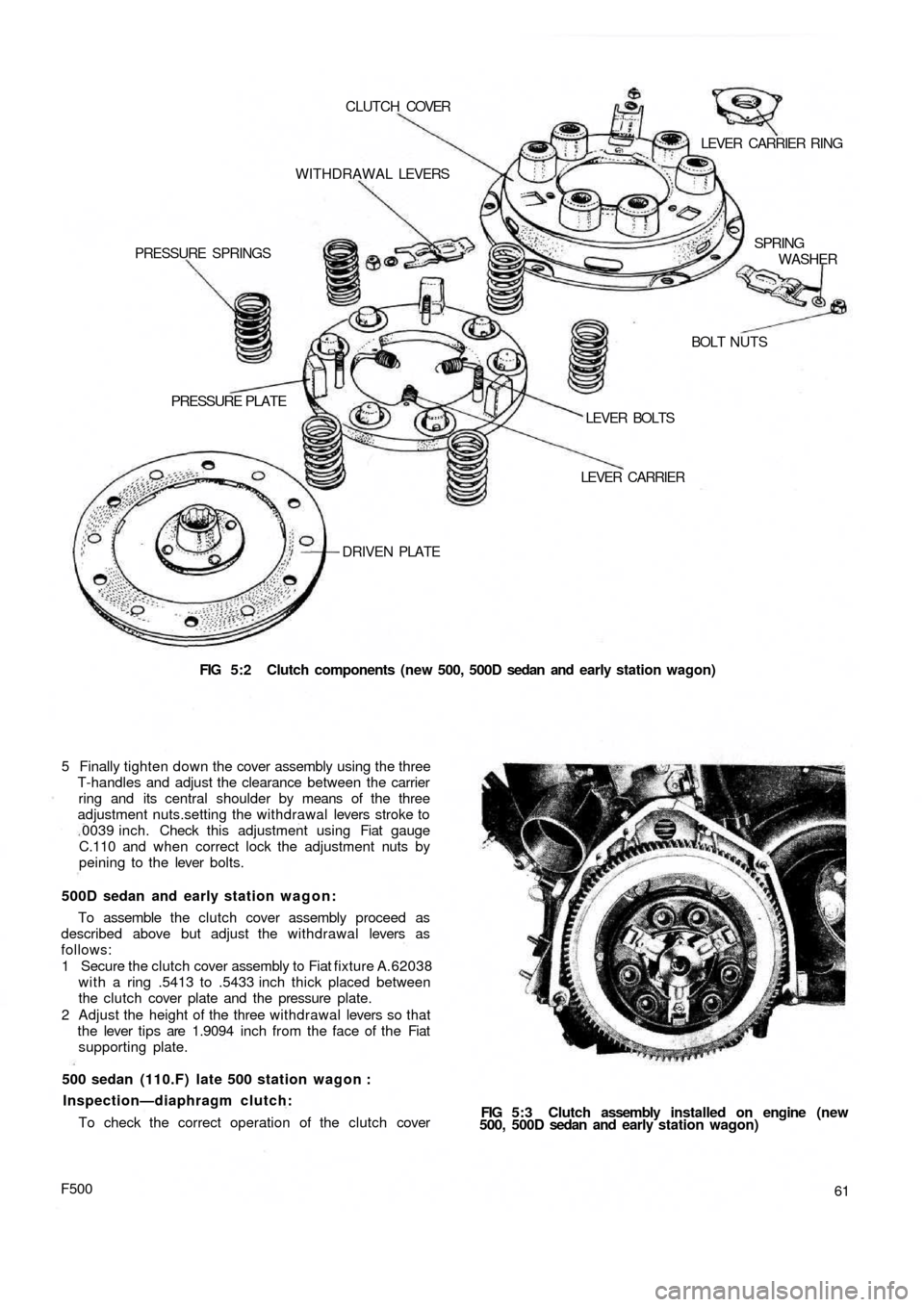
FIG 5:2 Clutch components (new 500, 500D sedan and early station wagon) DRIVEN PLATE
PRESSURE PLATE
LEVER CARRIER LEVER BOLTSBOLT NUTS PRESSURE SPRINGSWITHDRAWAL LEVERS CLUTCH COVER
LEVER CARRIER RING
SPRING
WASHER
FIG 5:3 Clutch assembly installed on engine (new
500, 500D sedan and early station wagon)
61
F500
To check the correct operation of the clutch cover 500 sedan (110.F) late 500 station wagon :
Inspection—diaphragm clutch: 5 Finally tighten down the cover assembly using the three
T-handles and adjust the clearance between the carrier
ring and its central shoulder by means of the three
adjustment nuts.setting the withdrawal levers stroke to
0039 inch. Check this adjustment using Fiat gauge
C.110 and when correct lock the adjustment nuts by
peining to the lever bolts.
500D sedan and early station wagon:
To assemble the clutch cover assembly proceed as
described above but adjust the withdrawal levers as
follows:
1 Secure the clutch cover assembly to Fiat fixture A.62038
with a ring .5413 to .5433 inch thick placed between
the clutch cover plate and the pressure plate.
2 Adjust the height of the three withdrawal levers so that
the lever tips are 1.9094 inch from the face of the Fiat
supporting plate.
Page 55 of 128
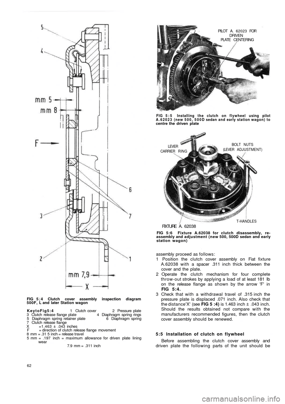
FIG 5 . 4 Clutch cover assembly inspection diagram
500F, L and later Station wagon
KeytoFig5:4 1 Clutch cover 2 Pressure plate
3 Clutch release flange plate 4 Diaphragm spring rings
5 Diaphragm spring retainer plate 6 Diaphragm spring
7 Clutch release flange
X =1.463 ± .043 inches
F = direction of clutch release flange movement
8 mm = .31 5 inch = release travel
5 mm = .197 inch = maximum allowance for driven plate lining
wear7.9 mm = .311 inch
62
5:5 Installation of clutch on flywheel
Before assembling the clutch cover assembly and
driven plate the following parts of the unit should be assembly proceed as follows:
1 Position the clutch cover assembly on Fiat fixture
A.62038 with a spacer .311 inch thick between the
cover and the plate.
2 Operate the clutch mechanism for four complete
throw-out strokes by applying a load of at least 181 Ib
on the release flange as shown by the arrow 'F' in
FIG 5:4.
3 Check that w i t h a withdrawal travel of .315 inch the
pressure plate is displaced .071 inch. Also check that
the distance'X' (see FIG 5 :4) is 1.463 inch ± .043 inch.
Should the results obtained not compare w i t h the
manufacturers recommended figures, then the clutch
cover assembly should be renewed.
FIG 5:6 Fixture A.62038 for clutch disassembly, re-
assembly and adjustment (new 500, 500D sedan and early
station wagon)
FIXTURE A . 62038
T-HANDLES CARRIER RING
LEVERBOLT NUTS
(LEVER ADJUSTMENT) FIG 5 : 5 Installing the clutch on flywheel using pilot
A.62023 (new 500, 500D sedan and early station wagon) to
centre the driven platePILOT A. 62023 FOR
DRIVENPLATE CENTERING
Page 56 of 128
lubricated using Fiat Jota 3 grease.
1 Pressure plate—boss outer faces.
2 Clutch cover—withdrawal lever fulcrum.
3 Withdrawal lever stopnuts—contact face.
4 Withdrawal lever carrier ring — lever contact face.
5 Crankcase end pilot bushing lubricated with Fiat KG.15
grease.
6 Lubricate contact faces of driven plate and clutch shaft.
To install the clutch assembly proceed as follows:
1 Ensure t h a t there is no grease or oil on the faces of the
driven plate or flywheel face and position with the
raised part of the hub towards the transmission unit.
2 Locate Fiat tool A.70085 (diaphragm clutch) or
A . 6 2 0 2 3 (coil spring clutch) or a suitably sized drift,
through the driven plate hub and position in crankshaft
pilot bushing. Gradually tighten the clutch unit
mounting screws working diagonally and finally tighten
to a torque wrench setting of 5.8 to 7.2 Ib ft.
5 : 6 Pilot bushing
Whenever the clutch unit is being renewed or over-
hauled it is essential that the crankshaft pilot bush is
checked for excessive wear or damage. Also check that
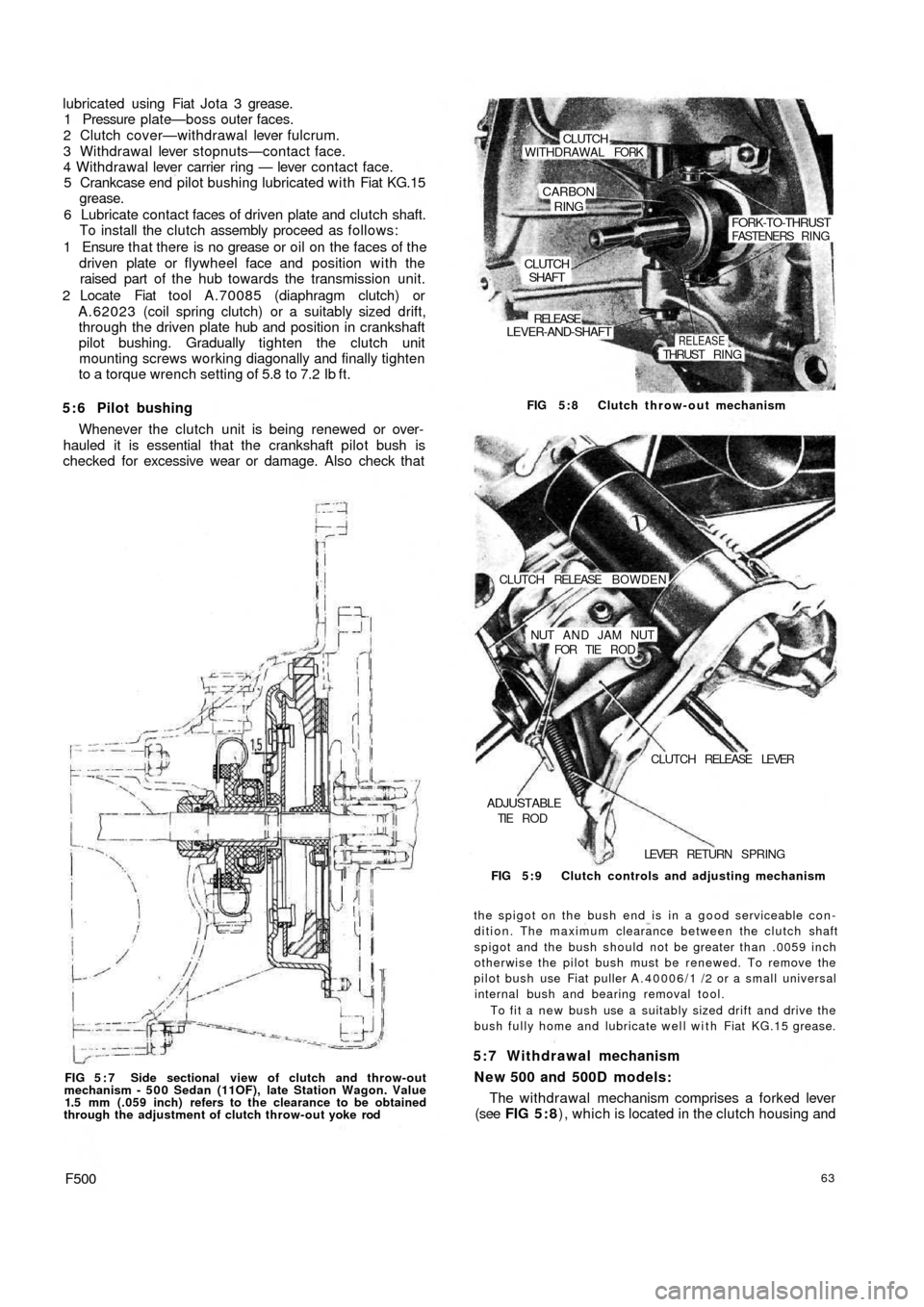
FIG 5 : 7 Side sectional view of clutch and throw-out
mechanism - 5 0 0 Sedan (11OF), late Station Wagon. Value
1.5 mm (.059 inch) refers to the clearance to be obtained
through the adjustment of clutch throw-out yoke rod
F50063
The withdrawal mechanism comprises a forked lever
(see FIG 5 : 8), which is located in the clutch housing and 5:7 Withdrawal mechanism
New 500 and 500D models:
the spigot on the bush end is in a good serviceable con-
dition. The maximum clearance between the clutch shaft
spigot and the bush should not be greater than .0059 inch
otherwise the pilot bush must be renewed. To remove the
pilot bush use Fiat puller A.40006/1 /2 or a small universal
internal bush and bearing removal tool.
To fit a new bush use a suitably sized drift and drive the
bush fully home and lubricate well with Fiat KG.15 grease. FIG 5 : 9 Clutch controls and adjusting mechanism LEVER RETURN SPRING
ADJUSTABLETIE R O DCLUTCH RELEASE LEVER NUT A N D JAM NUT
FOR TIE R O D CLUTCH RELEASE BOWDEN FIG 5:8 Clutch throw-out mechanism
CLUTCHSHAFT
LEVER-AND-SHAFT
RELEASE
RELEASETHRUST RING
FORK-TO-THRUSTFASTENERS RING
CARBON
RING
WITHDRAWAL FORKCLUTCH