1968 DATSUN 510 check oil
[x] Cancel search: check oilPage 160 of 252
DIFFERENTIAL
REAR
AXLE
AND
REAR
SUSPENSION
155
i
I
I
I
REAR
SUSPENSION
ARM
SEDAN
Rear
Suspension
Arm
Removal
Sedan
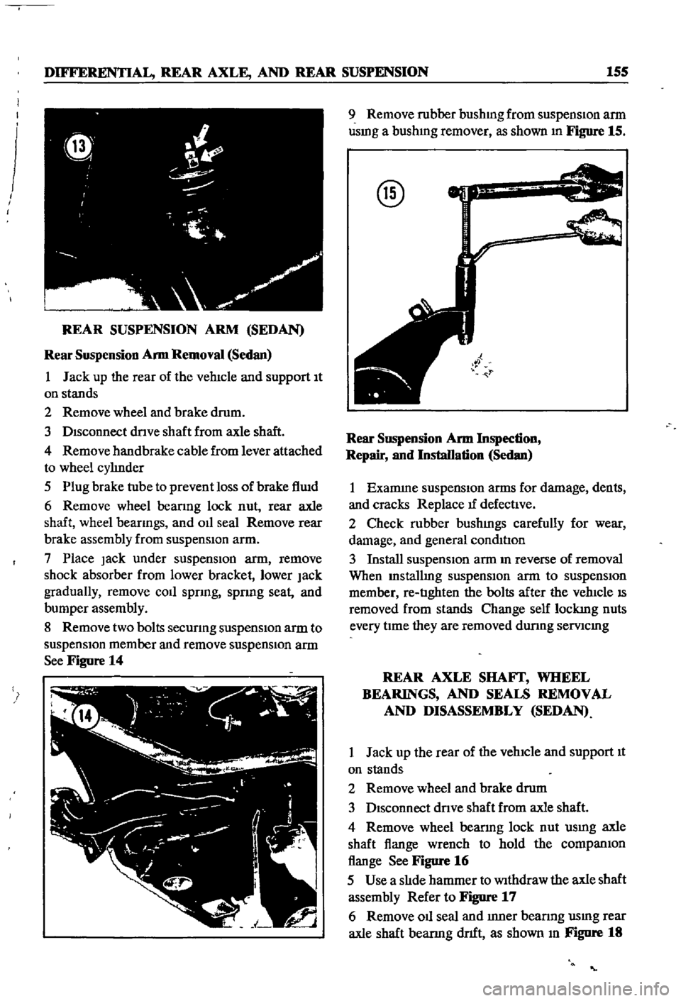
1
Jack
up
the
rear
of
the
vehIcle
and
support
It
on
stands
2
Remove
wheel
and
brake
drum
3
DIsconnect
dnve
shaft
from
axle
shaft
4
Remove
handbrake
cable
from
lever
attached
to
wheel
cylInder
5
Plug
brake
tube
to
prevent
loss
of
brake
flwd
6
Remove
wheel
beanng
lock
nut
rear
axle
shaft
wheel
beanngs
and
OIl
seal
Remove
rear
brake
assembly
from
suspensIOn
arm
7
Place
Jack
under
suspenSIon
arm
remove
shock
absorber
from
lower
bracket
lower
Jack
gradually
remove
coll
spnng
spnng
seat
and
bumper
assembly
8
Remove
two
bolts
secunng
suspensIOn
arm
to
suspensIOn
member
and
remove
suspensIOn
arm
See
Figure
14
9
Remove
rubber
bushmg
from
suspensIon
arm
usmg
a
bushmg
remover
as
shown
In
Figure
15
@
Rear
SllSpension
Arm
Inspection
Repair
and
Installation
Sedan
1
Examme
suspensIOn
arms
for
damage
dents
and
cracks
Replace
tf
defectIve
2
Check
rubber
bushmgs
carefully
for
wear
damage
and
general
condItIon
3
Install
suspensIOn
arm
m
reverse
of
removal
When
Installmg
suspensIOn
arm
to
suspensIOn
member
re
tIghten
the
bolts
after
the
vehIcle
IS
removed
from
stands
Change
self
lockmg
nuts
every
tIme
they
are
removed
dunng
semcmg
REAR
AXLE
SHAFf
WHEEL
BEARINGS
AND
SEALS
REMOVAL
AND
DISASSEMBLY
SEDAN
1
Jack
up
the
rear
of
the
vehIcle
and
support
It
on
stands
2
Remove
wheel
and
brake
drum
3
DIsconnect
dnve
shaft
from
axle
shaft
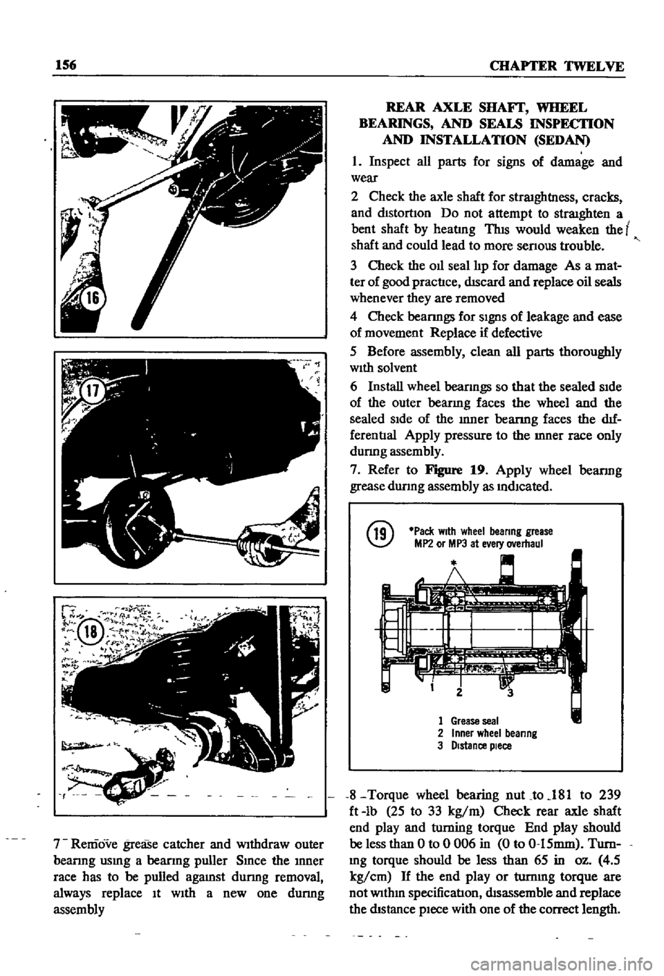
4
Remove
wheel
bearmg
lock
nut
usmg
axle
shaft
flange
wrench
to
hold
the
companIOn
flange
See
Figure
16
5
Use
a
slIde
hammer
to
Withdraw
the
axle
shaft
assembly
Refer
to
Figure
17
6
Remove
011
seal
and
Inner
bearmg
usmg
rear
axle
shaft
bearmg
dnft
as
shown
In
Figure
18
Page 161 of 252
156
CHAPTER
TWELVE
r
IV
rli
@
18
1
P
l
hr
r
J
oJ
1
it
o
1f
f
7
Remove
grease
catcher
and
Withdraw
outer
beanng
usmg
a
beanng
puller
Smce
the
Inner
race
has
to
be
pulled
agamst
dunng
removal
always
replace
It
WIth
a
new
one
dunng
assembly
REAR
AXLE
SHAFf
WHEEL
BEARINGS
AND
SEALS
INSPECTION
AND
INSTALLATION
SEDAN
1
Inspect
all
parts
for
signs
of
damage
and
wear
2
Check
the
axle
shaft
for
straIghtl1ess
cracks
and
dIStortIon
Do
not
attempt
to
straIghten
a
bent
shaft
by
heatlng
ThIS
would
weaken
the
t
shaft
and
could
lead
to
more
senous
trouble
3
Check
the
011
seal
IIp
for
damage
As
a
mat
ter
of
good
practIce
dIScard
and
replace
oil
seals
whenever
they
are
removed
4
Check
bearmgs
for
SIgnS
of
leakage
and
ease
of
movement
Replace
if
defective
5
Before
assembly
clean
all
parts
thoroughly
WIth
solvent
6
Install
wheel
beanngs
so
that
the
sealed
SIde
of
the
outer
bearmg
faces
the
wheel
and
the
sealed
SIde
of
the
Inner
bearmg
faces
the
dIf
ferentIal
Apply
pressure
to
the
Inner
race
only
dunng
assembly
7
Refer
to
Figure
19
Apply
wheel
bearmg
grease
durmg
assembly
as
mdlcated
@
Pack
With
wheel
beanng
grease
MP2
or
MP3
at
e
ery
overhaul
1
Grease
seal
2
Inner
wheel
beanng
3
Distance
piece
8
Torque
wheel
bearing
nuLto
181
to
239
ft
lb
25
to
33
kg
m
Check
rear
axle
shaft
end
play
and
wming
torque
End
play
should
be
less
than
0
to
0
006
in
0
to
0
15mm
Turn
Ing
torque
should
be
less
than
65
in
oz
4
5
kg
cm
H
the
end
play
or
turnmg
torque
are
not
WIthm
specification
dIsassemble
md
replace
the
dIStance
pIece
with
one
of
the
correct
length
Page 162 of 252

DIFFERENTIAL
REAR
AXLE
AND
REAR
SUSPENSION
157
DIFFERENTIAL
WAGON
The
dIfferentIal
carner
is
made
of
alumInum
alloy
and
uses
a
hypoid
bevel
gear
Proper
lubri
catIon
IS
essentIal
Check
and
replemsh
the
lub
rIcant
every
3
000
mIles
Dram
and
refill
every
30
000
mlles
Figure
20
IS
an
exploded
dIagram
of
the
differential
used
in
the
wagon
Difterential
Removal
Wagon
1
Jack
up
the
rear
wheels
and
support
vehicle
with
stands
l
2
DIsconnect
drIve
pmlon
companion
flange
to
yoke
connectIon
3
Remove
rear
wheel
axles
as
descnbed
later
m
thIS
chapter
4
Remove
dtfferentIal
from
vehIcle
Difterential
Inspection
Wagon
The
followmg
Inspection
can
be
done
Without
dISassembly
of
the
differentIal
Perform
the
fol
lOWIng
mspectIon
and
If
abnormalitIes
or
dam
age
eXISts
refer
further
service
and
repair
to
YOI
f
dealer
1
Check
the
tooth
contact
pattern
with
lead
oXIde
at
two
or
three
pomts
after
remoVIng
rear
cover
Refer
to
FIgure
5
for
correct
contact
pat
tern
If
the
pattern
IS
not
correct
dIsassembly
and
adjustment
of
the
dtfferentIalIS
reqUIred
2
Measure
backlash
between
dnve
gear
and
pInIOn
WIth
a
dIal
mdlcator
Backlash
should
be
00059
to
00079
in
0
15
to
0
20mm
3
Rotate
the
gears
and
lIsten
for
SIgnS
of
bear
Ing
nOIse
DefectIve
beanngs
should
be
replaced
by
a
dealer
4
Inspect
gear
teeth
for
signs
of
damage
or
cracks
r
Difterential
Installation
Wagon
Install
the
dIfferentIal
by
reversing
the
pro
cedures
used
for
removal
2
Olfferenllal
case
16
Pmlon
10Ckmg
pm
28
42
AdjusllRg
washer
t
3
Beanng
stud
17
Dlflerenbal
Side
beanng
43
47
Adjusting
shim
4
Plem
washer
18
22
Adjusting
shim
53
Oil
seal
5
Locking
nut
23
Rear
plRlOn
gear
54
Range
assembly
6
Lockmg
nut
24
Front
plRlOn
beanng
55
Nut
7
PIRlOn
gear
set
25
27
Spacer
56
Wesher
Iff
8
Hex
bolt
9
Bolt
locking
strap
7
10
Case
@
11
Side
gear
12
PmlOn
mete
is
Thrust
washer
13
14
Thrust
washer
10
15
PIRlOn
shaft
23
43
47
2S
27
7
J
I
18
22
17
l
24
S3
S6
S4
55
Page 166 of 252
DIFFERENTIAL
REAR
AXLE
AND
REAR
SUSPENSION
161
T
8
0
to
9
0
kg
m
57
8
to
65
11b
ft
@
T
2
8
to
3
9
kg
m
20
2
to
28
2
Ib
ft
Apply
grease
on
the
surface
of
the
collar
when
replacing
oil
seal
Brake
tube
T
1
7
to
2
0
kg
m
23
3
to
14
5
Ib
ft
Tread
1260
Use
the
shims
to
adjust
the
gap
C
between
the
wheel
bearing
and
the
recess
in
the
axle
tube
end
The
gap
should
be
beteewn
0
to
0
1
mm
0
to
0
0039
in
12
Fill
the
differentIal
housmg
With
specmed
lubncabng
011
REAR
SUSPENSION
WAGON
The
rear
suspensiOn
consists
of
semi
elhpnc
leaf
spnngs
hydraulJc
shock
absorbers
and
rub
ber
bumpers
Iso
clamp
deVices
are
used
for
attaching
the
axle
housmg
to
the
spnng
The
leaf
spnngs
shock
absorbers
and
rear
axle
hous
mg
are
mounted
on
rubber
bushmgs
at
each
end
See
Figure
22
REAR
SPRING
REMOVAL
INSPECTION
REPAIR
AND
INSTALLATION
WAGON
1
Jack
up
the
center
of
the
rear
axle
until
the
wheels
are
off
the
ground
Support
th
e
rear
end
With
stands
2
Remove
spare
tIre
3
Disconnect
shock
absorber
bottom
end
from
spnng
lower
seat
4
Loosen
rear
spring
U
bolt
nuts
Remove
bolts
bumper
assembhes
spring
seat
location
plates
and
seat
pads
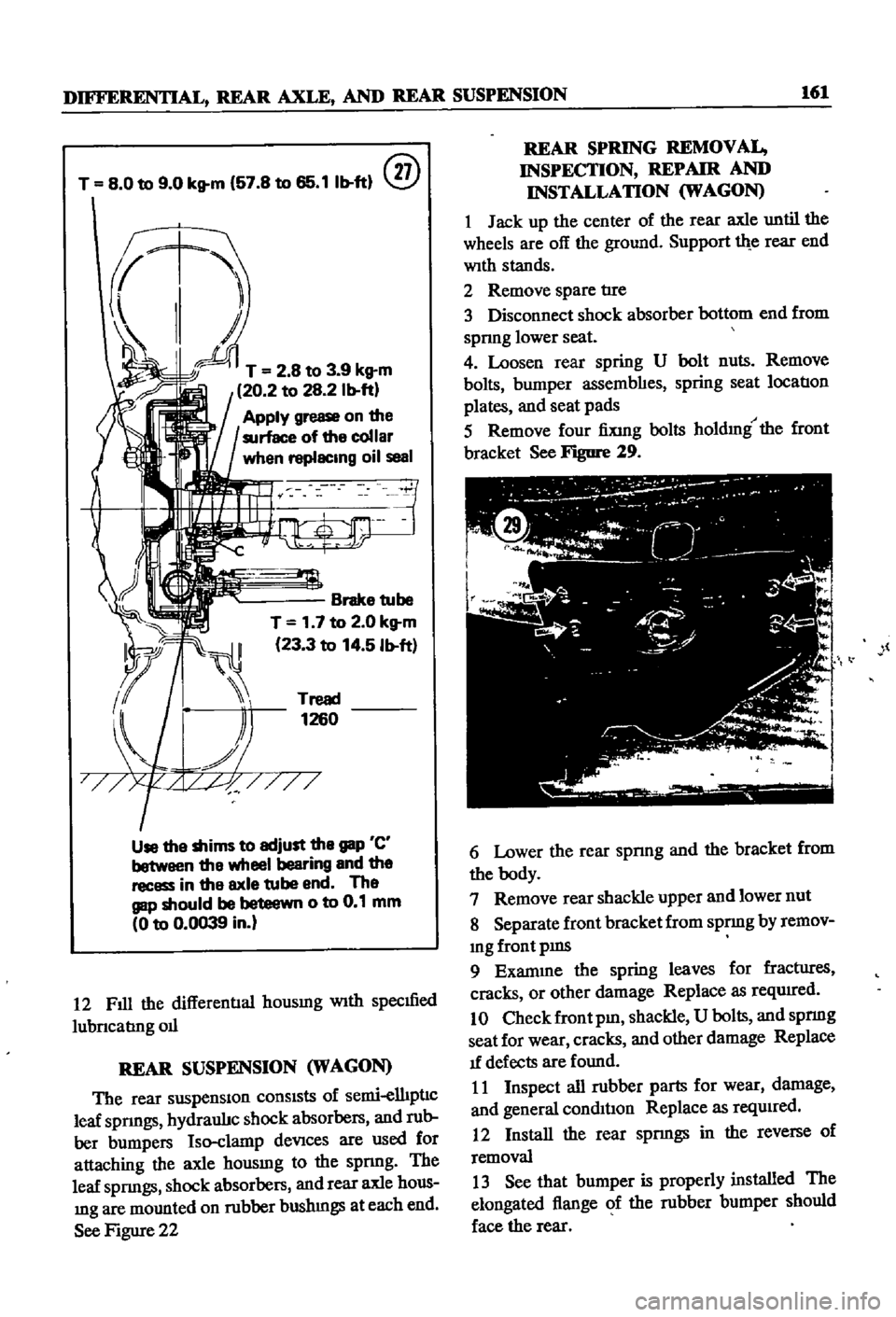
5
Remove
four
fiXing
bolts
holdmg
the
front
bracket
See
Figure
29
l
6
Lower
the
rear
spnng
and
the
bracket
from
the
body
7
Remove
rear
shackle
upper
and
lower
nut
8
Separate
front
bracket
from
spnng
by
remov
mg
front
pms
9
Exanune
the
spring
leaves
for
fractIires
cracks
or
other
damage
Replace
as
reqwred
10
Check
front
pm
shackle
U
bolts
and
spnng
seat
for
wear
cracks
and
other
damage
Replace
1f
defects
are
found
11
Inspect
all
rubber
parts
for
wear
damage
and
general
condil1on
Replace
as
reqUired
12
Install
the
rear
spnngs
in
the
reverse
of
removal
13
See
that
bumper
is
properly
installed
The
elongated
flange
of
the
rubber
bumper
should
face
the
rear
Page 181 of 252
176
CHAPTER
TInRTEEN
@
dnlled
tapped
and
a
bolt
mserted
to
use
as
a
plug
puller
Refer
to
Figure
16
r
r
t
t
rJ
11
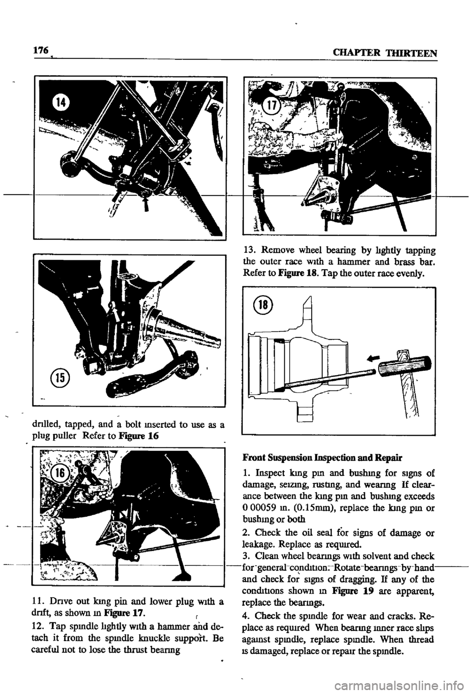
Dnve
out
kmg
pin
and
lower
plug
With
a
dnft
as
shown
m
Figure
17
r
12
Tap
spmdle
hghtly
With
a
hanrmer
and
de
tach
it
from
the
spmdle
knuckle
suppoh
Be
careful
not
to
lose
the
thrust
bearmg
13
Remove
wheel
bearing
by
hghtly
tapping
the
outer
race
WIth
a
hanrmer
and
brass
bar
Refer
to
Figure
18
Tap
the
outer
race
evenly
@
Front
Suspension
Inspection
nnd
Repair
1
Inspect
kmg
pm
and
bushmg
for
SIgnS
of
damage
selZlDg
rustIng
and
wearmg
If
clear
ance
between
the
kmg
pm
and
bushmg
exceeds
000059
m
0
15mm
replace
the
kmg
pm
or
bushmg
or
both
2
Check
the
oil
seal
for
signs
of
damage
or
leakage
Replace
as
reqUIred
3
Clean
wheel
bearmgs
With
solvent
and
check
for
general
co
nmtIon
Rotate
bearmgs
by
hand
and
check
for
SIgnS
of
dragging
If
any
of
the
conmtJons
shown
m
Figure
19
are
apparent
replace
the
bearmgs
4
Check
the
spmdle
for
wear
and
cracks
Re
place
as
reqwred
When
beanng
mner
race
shps
agaJDst
spmdle
replace
spmdle
When
thread
IS
damaged
replace
or
reparr
the
spmdle
Page 198 of 252
BRAKES
193
Front
Disc
Brake
Piston
Seal
Replacement
If
oil
leakage
is
detected
around
the
piston
seal
It
should
be
replaced
as
follows
I
Rinse
the
cyhnder
bore
With
brake
flwd
In
sert
new
seal
into
the
groove
taking
care
not
to
damage
It
Attach
the
wiper
seal
Lubricate
cylinder
bore
lightly
With
brake
fluid
2
Clean
the
piston
Inspect
the
pISton
for
scor
ing
or
other
damage
before
inserting
It
Make
sure
that
the
relieved
portion
of
the
pISton
faces
the
pivot
pin
Prevent
tilting
of
the
piston
when
It
IS
mserted
mto
the
cyhnder
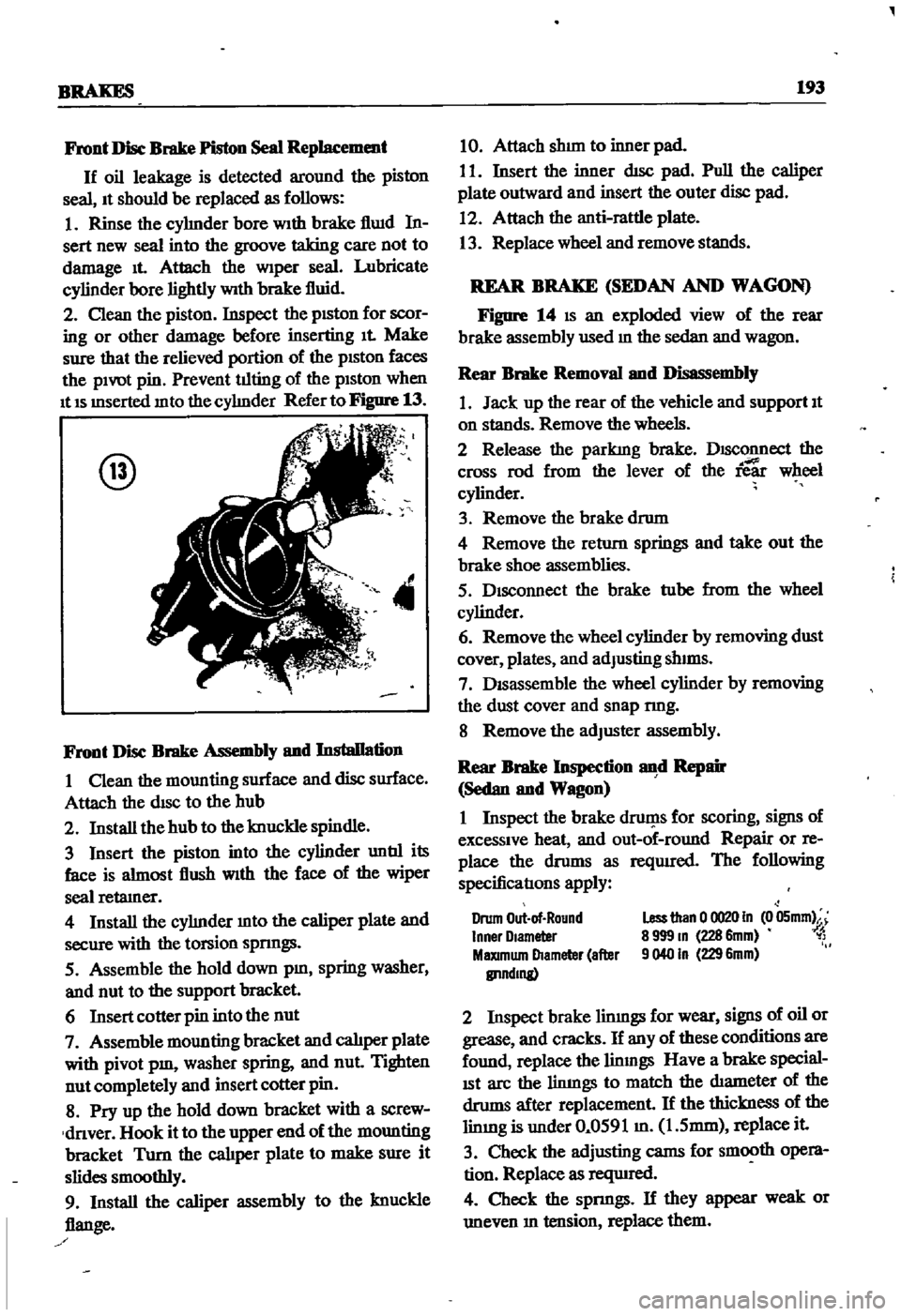
Refer
to
Figure
13
@
4
Front
Disc
Brake
Assembly
and
Installation
I
Clean
the
mounting
surface
and
disc
surface
Attach
the
disc
to
the
hub
2
Install
the
hub
to
the
knuckle
spindle
3
Insert
the
piston
into
the
cylinder
untIl
its
face
is
almost
flush
With
the
face
of
the
wiper
seal
retamer
4
Install
the
cyhnder
mto
the
caliper
plate
and
secure
with
the
torsion
spnngs
5
Assemble
the
hold
down
pm
spring
washer
and
nut
to
the
support
bracket
6
Insert
cotter
pin
into
the
nut
7
Assemble
mounting
bracket
and
calJper
plate
with
pivot
pm
washer
spring
and
nut
Tighten
nut
completely
and
insert
cotter
pin
8
Pry
up
the
hold
down
bracket
with
a
screw
dnver
Hook
it
to
the
upper
end
of
the
mounting
bracket
Turn
the
cal1per
plate
to
make
sure
it
slides
smoothly
9
Install
the
caliper
assembly
to
the
knuckle
flange
10
Attach
shun
to
inner
pad
I
I
Insert
the
inner
dIsc
pad
Pull
the
caliper
plate
outward
and
insert
the
outer
disc
pad
12
Attach
the
anti
rattle
plate
13
Replace
wheel
and
remove
stands
REAR
BRAKE
SEDAN
AND
WAGON
Figure
14
IS
an
exploded
view
of
the
rear
brake
assembly
used
m
the
sedan
and
wagon
Rear
Brake
Removal
and
Disassembly
1
Jack
up
the
rear
of
the
vehicle
and
support
It
on
stands
Remove
the
wheels
2
Release
the
parkIng
brake
DISConnect
the
cross
rod
from
the
lever
of
the
ie
wheel
cylinder
3
Remove
the
brake
drum
4
Remove
the
return
springs
and
take
out
the
brake
shoe
assemblies
5
Disconnect
the
brake
tube
from
the
wheel
cylinder
6
Remove
the
wheel
cylinder
by
removing
dust
cover
plates
and
adJusting
shIms
7
DISassemble
the
wheel
cylinder
by
removing
the
dust
cover
and
snap
nng
8
Remove
the
adJuster
assembly
Rear
Brake
Inspection
d
Repair
Sedan
and
Wagon
I
Inspect
the
brake
druf
1s
for
scoring
signs
of
excessive
heat
and
out
of
round
Repair
or
re
place
the
drums
as
reqUIred
The
following
specificatIons
apply
Drum
Out
of
Round
Inner
Olameter
MaXImum
Diameter
after
IlI1ndmg
Less
than
0
0020
In
0
05mm
8
999
m
228
6mm
1
9040
In
229
6mm
2
Inspect
brake
limngs
for
wear
signs
of
oil
or
grease
and
cracks
If
any
of
these
conditions
are
found
replace
the
linmgs
Have
a
brake
special
ISt
arc
the
limngs
to
match
the
diameter
of
the
drums
after
replacement
If
the
thickness
of
the
limng
is
under
0
0591
m
1
5mm
replace
it
3
Check
the
adjusting
cams
for
smooth
opera
tion
Replace
as
reqUIred
4
Check
the
spnngs
If
they
appear
weak
or
uneven
m
tension
replace
them
Page 243 of 252
INDEX
237
2
7
30
28
WIrIng
diagrams
WIrIng
harnesses
Electncal
system
engme
Alternator
Chargmg
ClfCUlt
Dlstnbutor
IgmtlOn
coIl
Spark
plugs
Starter
Voltage
regulator
Emission
control
crankcase
DescnptIon
General
mspectIon
SchematIc
vIew
VentIlatIOn
control
valve
EmIssIOn
control
exhaust
AIr
pump
AntI
backfire
valve
Check
valve
DescnptlOn
Engme
modificatIons
system
Exploded
and
schematIc
vIews
Mamtenance
and
testIng
Troubleshootmg
Emission
control
system
evaporatIve
Engme
Camshaft
and
beanngs
Camshaft
sprocket
Component
descnptIons
Componenl
reassembly
and
mstallatIon
CompressIOn
testmg
Connectmg
rod
beanngs
Connectmg
rods
Crankshaft
Crankshaft
and
tImmg
cham
Crankshafl
sprocket
Cylmder
block
CylInder
head
DescnptlOn
Disassembly
Exploded
view
Flywheel
InstallatIOn
LubncatIon
MaIO
bearmgs
PIston
nngs
Pistons
and
connectmg
rods
PiStOns
and
piston
pms
Reassembly
Removal
SectIonal
views
ServIce
data
SpeCificatIons
Troubleshootmg
Valve
rocker
PIvot
Valves
Engme
lubncatlon
DescnptIon
217
222
205
207
98
104
98
105
111
111
112
113
9197
104
122
122
121
38
114
123
115
120
114
15
123
48
54
53
31
38
5759
24
52
51
54
51
57
53
49
55
46
56
31
40
33
53
59
27
30
52
50
45
50
54
53
38
32
60
61
60
61
13
54
47
53
114
114
121
114
LubncatlOn
ClfCUlt
011
filter
011
pump
Engme
tune
up
Checks
miscellaneous
Compression
testIng
DIstributor
Dwell
angle
EqUIpment
usage
ReqUIred
eqUIpment
Spark
plugs
Tlmmg
Tlmmg
dual
pomt
dlstnbutor
Valve
clearances
Exhaust
systems
Exploded
views
InspectIon
InstallatIOn
Removal
pickup
Removal
sedan
and
wagon
F
Fan
clutch
DIsassembly
and
reassembly
OperatIon
and
mspectlon
Flywheel
Fuel
pump
Capacity
test
DescnptlOn
Exploded
views
InspectIOn
InstallatIOn
Reassembly
Removal
an
assembly
StatIc
pressure
test
Fuel
stramer
Fuel
system
Air
cleaner
Carburetor
Fuel
pump
Fuel
stramer
Fuel
tank
Troubleshootmg
Fuel
tank
DescnptIon
Exploded
Views
InspectIOn
and
repaIr
Installation
Removal
sedan
Removal
pick
up
Removal
wagon
Fuses
G
27
General
mformatIon
25
24
21
24
20
20
21
23
24
25
124
126
126
126
126
123
l
89
89
53
68
37
65
66
67
68
58
68
42
68
65
1
2v
62
69
65
68
l
6
7
1
l
76
78
81
82
82
76
82
7
6
2
1
F
Page 244 of 252
138
INDEX
H
OIl
pump
Descnptlon
36
Handbrake
Exploded
view
29
Adjustment
202
Inspection
and
repaIr
28
Cable
removal
front
sedan
and
wagon
197
Installation
58
Cable
removal
rear
pick
up
201
Removal
28
40
Cable
removal
rear
sedan
and
wagon
197
Cross
rod
removal
wagon
201
Exploded
views
198
200
p
Inspection
and
repair
201
Installation
201
Penodlc
mamtenance
Headlights
MaIntenance
mtervals
chart
7
Bulb
replacement
210
Penodlc
checks
6
Descnptlon
210
Recommended
lubncants
8
Exploded
view
219
Routine
checks
6
HeatIng
system
Piston
nngs
Descnptlon
210
Exploded
view
pick
up
213
Inspection
50
Exploded
VIews
sedan
and
wagon
214
215
Removal
45
Hood
lock
control
RIng
gap
50
Exploded
View
pick
up
225
Pistons
Descnptlon
34
Exploded
VIew
sedan
and
wagon
226
Inspection
50
Reassembly
54
Igmtlon
coil
111
R
Igmtlon
system
Tlmmg
23
Radiator
Troubleshooting
13
Exploded
view
90
Instrument
meters
and
panels
Removal
and
replacement
90
Descnptlon
210
Rear
axle
pick
up
Exploded
View
pick
up
213
Axle
case
166
Exploded
view
sedan
and
wagon
Inspection
and
mstalIatlon
164
1970
1972
212
Removal
164
Exploded
view
sedan
and
wagon
Sectional
view
163
through
1969
211
Rear
axle
wagon
Intake
manifold
Disassembly
158
Descnptlon
36
Exploded
view
158
Removal
42
Inspection
and
reassembly
160
InstallatIOn
160
Removal
158
M
Rear
axle
and
suspenSion
sedan
Exploded
view
152
153
Mam
beanngs
52
Inspection
and
repaIr
154
MaIntenance
penodlc
6
8
InstalIatlon
154
Master
cylInder
Removal
151
Exploded
vIew
smgle
188
Rear
spnngs
pick
up
166
Exploded
view
tandem
189
Rear
spnngs
wagon
161
Inspection
and
repllIr
188
Rear
axle
shaft
sedan
155
156
Reassembly
and
InstalIatlon
190
Rear
suspension
arm
sedan
155
Removal
and
disassembly
188
Rear
suspenSion
pick
up
Modelldentdicatlon
1
Exploded
view
166
Inspection
and
repllIr
167
InstalIatlon
167
0
Rear
spnngs
166
Removal
165
011
filler
30
Spnngs
166
d
43
Torques
67