1968 DATSUN 510 fuel cap
[x] Cancel search: fuel capPage 64 of 252

ENGINE
59
2
Coat
the
pan
gasket
on
both
sides
With
gasket
compound
and
attach
the
oil
pan
to
the
cyhnder
block
Torque
as
specIfied
Manifold
and
Carburetor
Installation
1
Install
the
mtake
and
exhaust
manIfolds
WIth
associated
gasket
to
the
cylmder
head
2
Mount
the
carburetor
and
gasket
to
the
mtake
manIfold
2
Adjust
all
mtake
and
exhaust
valves
to
the
specIfied
clearance
for
a
cold
engme
Clutch
Assembly
Installation
CAUTION
Take
extreme
care
not
to
get
grease
or
011
on
the
clutch
or
flywheel
frlc
hon
contact
surfaces
1
Place
the
clutch
disc
assembly
on
the
flywheel
With
the
longer
chamfered
splmed
end
of
the
dISC
toward
the
transmISSion
2
Visually
align
or
use
a
dummy
splmed
dnve
shaft
to
ahgn
the
diSC
assembly
With
the
flywheel
pilot
beanng
3
Install
and
tighten
the
SIX
bolts
holdmg
the
clutch
cover
assembly
to
the
flywheel
Tighten
the
bolts
a
turn
each
tune
by
diagonal
pattern
until
they
are
tight
Tlghtenmg
torque
should
be
174
to
188ft
lbs
24
to
2
6
kg
m
NOTE
There
are
two
dowels
on
the
flywheel
to
locate
the
clutch
cover
4
Remove
dummy
shaft
If
used
after
the
above
bolts
are
fully
tightened
5
Refit
the
release
bearing
and
translI11Ssion
case
Miscellaneous
Installation
1
Connect
the
fuel
hose
on
the
front
part
of
the
engme
to
the
fuel
pump
and
to
the
carburetor
2
Gap
the
spark
plugs
and
mstall
them
usmg
new
gaskets
3
Coat
the
rocker
arm
cover
gasket
With
sealer
and
position
It
on
the
cylmder
head
4
Install
the
rocker
arm
cover
and
tighten
the
two
thumb
screws
that
hold
it
m
place
5
Install
distrIbutor
makmg
certam
that
the
notch
on
the
distributor
shaft
assembly
mates
With
the
drive
spmdle
Ahgn
the
location
marks
made
dunng
disassembly
so
that
the
distrIbutor
is
positioned
as
before
6
Install
and
tighten
the
bolts
which
hold
the
dIStributor
to
the
front
cover
7
Install
pomts
condenser
and
rotor
8
Replace
distrIbutor
cap
and
attach
spark
plug
Wires
m
the
correct
sequence
Make
certain
that
all
wires
are
firmly
seated
m
the
distrIbutor
cap
and
attached
securely
to
the
spark
plugs
9
HOISt
the
engme
assembly
from
the
work
stand
10
Install
the
alternator
bracket
alternator
and
engme
mounts
to
the
block
11
Install
the
IgnItIon
coil
oil
filter
oil
pressure
SWitch
dipstick
and
water
drain
plug
12
Connect
the
vacuum
Ime
between
the
dis
trIbutor
and
carburetor
13
Connect
the
transIDlSSlOn
to
the
engine
prior
to
mstallatIon
m
the
vehicle
Engine
Installation
Installation
is
the
reverse
of
the
procedures
followed
m
removal
Be
certaIn
thatlall
battery
connections
are
made
that
water
hoses
are
se
cured
wmng
IS
connected
properly
and
that
all
required
bolts
and
mounts
are
mstalled
and
tightened
Replace
the
radiator
fan
belts
and
radiator
shroud
Fill
the
engme
With
the
proper
grade
of
oil
and
the
radiator
With
recommended
coolant
Install
the
hood
to
the
hInges
according
to
the
marks
made
dUrIng
removal
SERVICE
DATA
AND
SPECIFICATIONS
Table
1
covers
servIce
data
and
engme
Speci
fications
Page 70 of 252
FUEL
SYSTEM
6S
CD
2
Remove
the
fuel
stramer
from
Its
mountlng
clIp
3
Replace
the
fuel
stramer
as
reqUIred
4
Reconnect
the
mtake
and
outlet
fuellmes
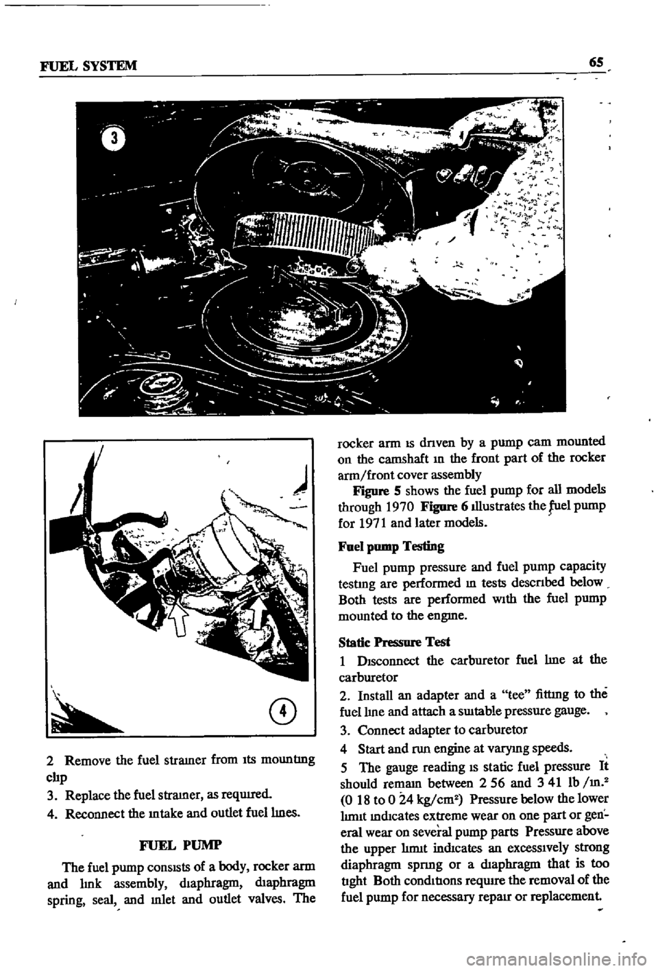
FUEL
PUMP
The
fuel
pump
conSISts
of
a
body
rocker
arm
and
lmk
assembly
dIaphragm
dIaphragm
spring
seal
and
mlet
and
outlet
valves
The
l
r
t
1
9
l
F
r
fl
rocker
arm
IS
dnven
by
a
pump
cam
mounted
on
the
catnShaft
In
the
front
part
of
the
rocker
arm
front
cover
assembly
Figure
S
shows
the
fuel
pump
for
all
models
through
1970
Figure
6
illustrates
the
fuel
pump
for
1971
and
later
models
Fuel
pump
Testing
Fuel
pump
pressure
and
fuel
pump
capacity
testlng
are
performed
m
tests
descnbed
below
Both
tests
are
performed
With
the
fuel
pump
mounted
to
the
engme
Static
Pressure
Test
1
DIsconnect
the
carburetor
fuel
lme
at
the
carburetor
2
Install
an
adapter
and
a
tee
fittmg
to
the
fuel
lIne
and
attach
a
SUItable
pressure
gauge
3
Connect
adapter
to
carburetor
4
Start
and
run
engine
at
varymg
speeds
5
The
gauge
reading
IS
static
fuel
pressure
It
should
remam
between
256
and
341
Ib
m
2
018
to
0
24
kg
cm2
Pressure
below
thelower
lImIt
mdlcates
extreme
wear
on
one
part
or
gen
eral
wear
on
several
pump
parts
Pressure
above
the
upper
hrmt
indIcates
an
excessIvely
strong
diaphragm
spnng
or
a
dIaphragm
that
is
too
tIght
Both
condItIons
require
the
removal
of
the
fuel
pump
for
necessary
repaIr
or
replacement
Page 73 of 252
68
CHAPTER
SEVEN
Capacity
Test
Perform
the
capacity
test
only
when
the
statIc
pressiue
test
IS
withm
acceptable
lirmts
1
D
sconnect
the
fuellme
at
the
carburetor
2
Place
a
sUItable
container
at
the
end
of
the
fuellme
3
St
lrt
the
engm
and
run
at
OOO
rpm
4
The
fuel
pump
should
delIver
fuel
into
the
co
ntainer
at
a
rate
slightly
over
two
pints
per
minute
If
no
gasolme
or
only
a
lIttle
appears
the
fuel
lme
is
clogged
or
thefuel
pump
defectIve
Bef
removmg
the
fuel
pump
remove
the
gas
tank
filler
cap
dtsconnect
the
mlet
and
outlet
fuel
lmes
and
qlow
through
them
With
compressed
air
to
make
certam
they
are
clear
Reconnect
the
fuellmes
and
retest
the
flow
If
stIll
insufficient
the
fuel
p
mp
requires
servicmg
or
replacement
Fuel
Punip
Removal
and
Disassembly
1
Unscrew
the
two
mountIng
nuts
hOldmg
fuel
pump
to
the
cylmder
head
2
Disconnect
the
inlet
and
outlet
lines
3
Remove
the
fuel
pump
from
the
cylmder
head
4
Place
the
pump
on
a
work
bench
and
remove
the
screws
jommg
the
upper
and
lower
bodIes
5
Remove
the
cap
and
gasket
by
removing
the
cap
screws
6
Unscrew
the
elbow
and
connector
7
Remove
the
valve
retamer
by
unscrewmg
the
two
valve
retamer
screws
The
two
valves
are
then
easily
removed
8
To
remove
the
dIaphragm
spring
lower
body
seal
washer
and
lower
body
seal
from
the
lower
body
press
the
diaphragm
down
Wh1le
domg
thIS
cant
the
dIaphragm
so
that
the
rectangular
part
m
the
lower
end
of
the
pull
rod
unhooks
from
the
rocker
arm
lmk
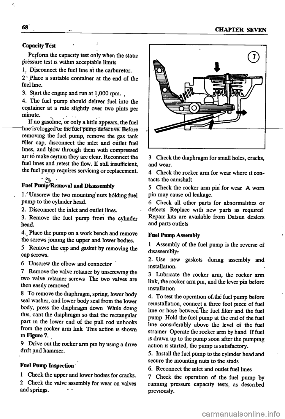
ThIS
action
IS
shown
mFigure7
9
Drive
out
the
rocker
arm
pm
by
usmg
a
dnve
dnft
nd
hammer
Fuel
Pump
Inspection
1
Check
the
upper
and
lower
bodIes
for
cracks
2
Check
the
valve
assembly
for
wear
on
valves
and
springs
CD
3
Check
the
diaphragm
for
small
holes
cracks
and
wear
4
Check
the
rocker
arm
for
wear
where
It
con
tacts
the
camshaft
5
Check
the
rocker
arm
pin
for
wear
A
worn
pin
may
cause
011
leakage
6
Check
all
other
parts
for
abnormalItIes
or
defects
Replace
With
new
parts
as
reqUlred
Reparr
kIts
are
available
from
Datsun
dealers
and
parts
outlets
Fuel
Pump
Assembly
1
Assembly
of
the
fuel
pump
is
the
reverse
of
dlsassembly
2
Use
new
gaskets
durmg
assembly
and
mstanatIon
3
Lubncate
the
rocker
arm
the
rocker
arm
link
the
rocker
arm
pm
and
the
lever
pin
before
mstallatIon
4
To
test
the
operatIon
ohhe
fuel
pump
before
remstallatlOn
connect
a
three
foot
pIece
of
fuel
lme
or
hose
betweentbe
fuel
filter
and
the
fuel
pump
Hold
the
fuel
pump
at
the
end
of
the
fuel
lme
conSIderably
above
the
level
of
the
fuel
stramer
Operate
the
rocker
arm
by
hand
If
fuel
IS
drawn
up
to
the
pump
soon
after
the
pumpmg
actIon
IS
started
the
pump
IS
satIsfactory
5
Install
the
fuel
pump
to
the
cylmder
head
and
secure
the
mounting
nuts
to
the
studs
6
Reconnect
the
mlet
and
outlet
fuellmes
7
Check
the
operatIon
of
the
fuel
pump
by
runnmg
pressure
capaCIty
tests
as
descnbed
preVIously
Page 82 of 252
8
1
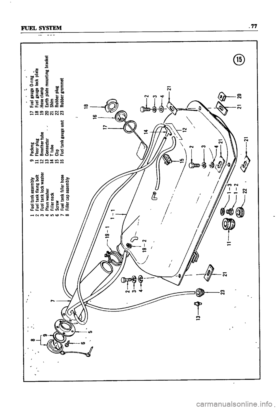
Fuel
tank
Bssembly
2
Fue
tank
fixing
bolt
3
Fuel
tank
lock
washBr
4
Plain
washer
5
Filler
neck
6
Screw
7
Fuel
tank
filler
hOS8
8
Filler
cap
Bssembly
9
Packing
11
Floor
plug
12
BrBather
tube
13
Connector
14
T
tube
15
Clip
16
Fuel
tank
gauge
umt
17
Fuel
gaUgB
O
nng
18
Fuel
gauge
lock
plate
19
Hose
clamp
20
Earth
plate
mounting
bracket
21
Shim
22
Rubber
plug
23
Rubber
grommB
7
13
Id
@
t
I
l
I
1
Page 83 of 252
23
19
21
20
I
13
11
12
I
14
L
1
A
21
I
26
TO
CRANK
CASE
@
1
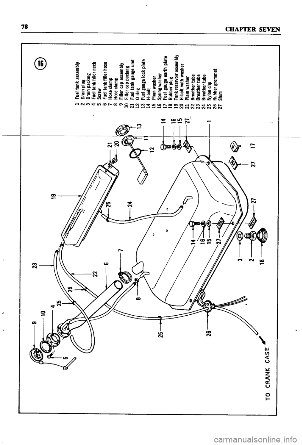
Fuel
tank
assembly
2
Drain
plug
3
Drain
packing
4
Fuel
tank
filler
neck
5
Screw
6
Fuel
tank
filler
hose
7
Hose
clamp
8
Hose
clamp
9
Filler
cap
assembly
10
Filler
cap
packing
11
Fuel
tank
gauge
umt
12
0
ring
13
Fuel
geuge
loc
l
plate
14
H
bolt
15
Plain
washer
16
Spnng
wesher
17
Fuel
gauge
earth
plale
18
Rubber
plug
19
Tank
reseNOlr
essembly
20
H
bolt
With
washer
21
Plein
washer
22
Breather
tube
23
Breather
tube
24
Breether
tube
25
Nylon
clip
26
Rubber
grommet
27
Shim
QD
g
j
Page 85 of 252
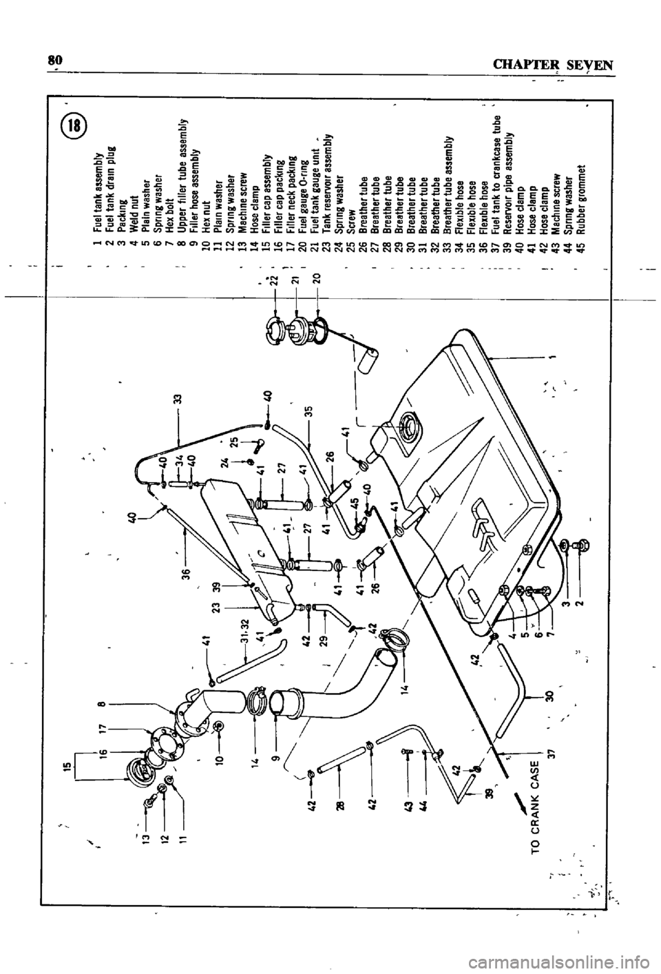
QO
@
15
I
1
Fuellank
assembly
17
8
2
Fuel
tank
drain
plug
3
Packing
4
Weld
nul
5
Plain
washer
6
Spllng
washer
7
Hex
bolt
33
8
Upper
filler
tube
assembly
9
Filler
hose
assembly
10
Hex
nut
11
Plain
washer
U
12
Spllng
washer
25
13
Machine
screw
rt
41
40
14
Hose
clamp
2i
15
Filler
cap
assembly
27
J
16
Filler
cap
packing
L
1
17
Filler
neck
packing
21
35
20
Fuel
gauge
O
lIng
20
21
Fuel
tank
gauge
Unit
23
Tank
reservoll
assembly
24
Spllng
washer
25
Screw
26
Breather
tube
27
Breather
tube
28
Breather
lube
29
Breather
tube
30
Breather
tube
31
Breather
tube
32
Breather
tube
33
Breather
tube
assembly
34
flexible
hose
35
Flexible
hose
36
flexible
hose
37
Fuel
tank
to
crankcase
tube
a
39
Reservoll
pipe
assembly
TO
CR
CASE
I
Y
40
Hose
clamp
41
Hose
clamp
I
42
Hose
clamp
37
30
1
43
Machine
screw
44
Spllng
washer
rIJ
45
Rubber
grommet
I
fi
j
Page 87 of 252
82
CHAPTER
SEVEN
Removal
Pick
up
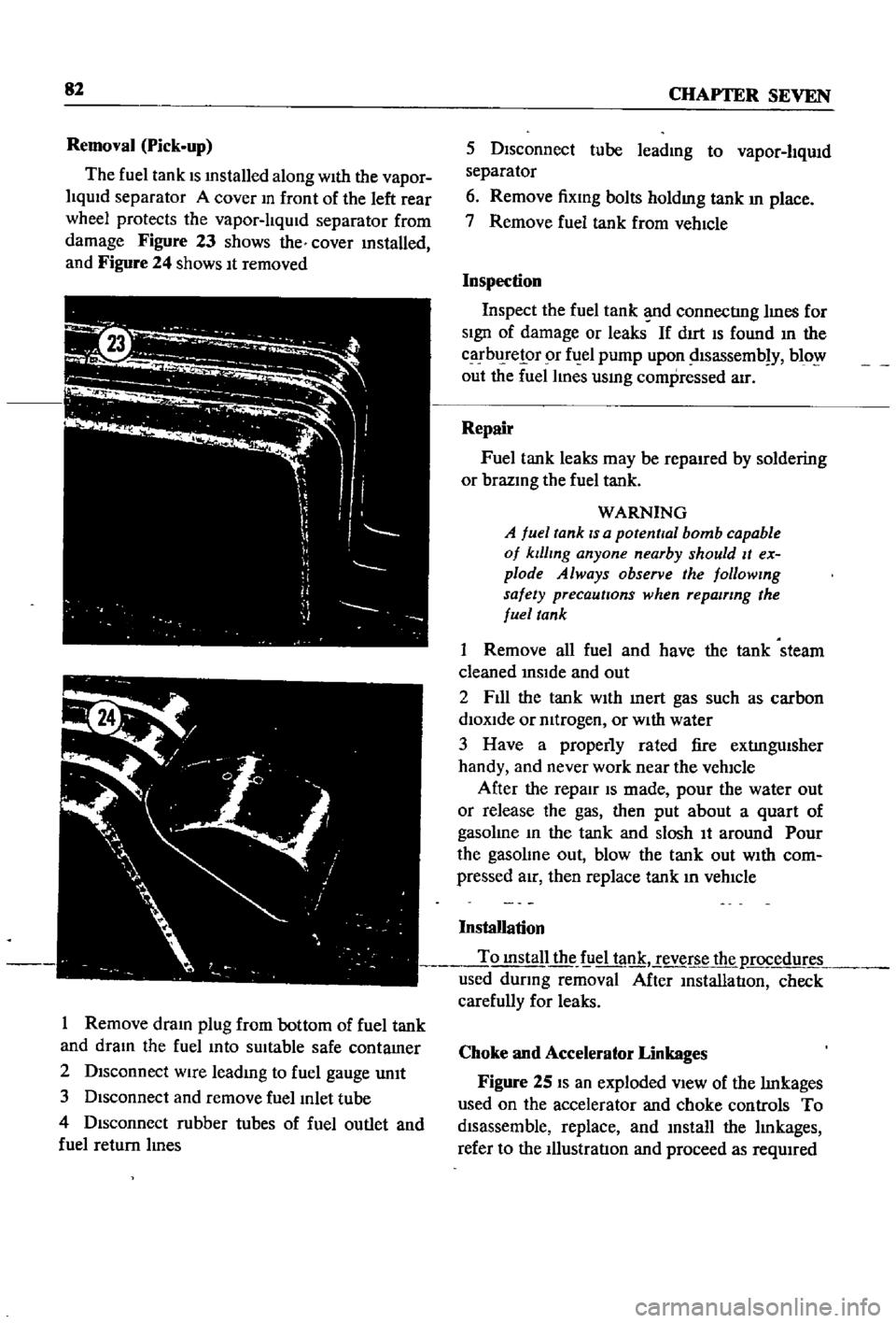
The
fuel
tank
IS
mstalled
along
With
the
vapor
liqUid
separator
A
cover
m
front
of
the
left
rear
wheel
protects
the
vapor
lIqUid
separator
from
damage
Figure
23
shows
the
cover
mstalled
and
Figure
24
shows
It
removed
I
Remove
dram
plug
from
bottom
of
fuel
tank
and
dram
the
fuel
mto
sUitable
safe
contamer
2
Disconnect
wire
leadmg
to
fuel
gauge
unIt
3
Disconnect
and
remove
fuel
Inlet
tube
4
Disconnect
rubber
tubes
of
fuel
outlet
and
fuel
return
lInes
5
Disconnect
tube
leadmg
to
vapor
liqUid
separator
6
Remove
fixmg
bolts
holdmg
tank
In
place
7
Remove
fuel
tank
from
vehIcle
Inspection
Inspect
the
fuel
tank
d
connectIng
lInes
for
SIgn
of
damage
or
leaks
If
dIrt
IS
found
In
the
carbl
relor
r
fuel
pump
upon
dlsassemb
y
blo
out
the
fuel
lines
usmg
compressed
air
Repair
Fuel
tank
leaks
may
be
repaired
by
soldering
or
brazmg
the
fuel
tank
WARNING
A
fuel
tank
IS
a
potential
bomb
capable
of
klllmg
anyone
nearby
should
It
ex
plode
Always
observe
the
followmg
safety
precautions
when
repairing
the
fuel
tank
1
Remove
all
fuel
and
have
the
tank
steam
cleaned
InSIde
and
out
2
F1l1
the
tank
WIth
Inert
gas
such
as
carbon
diOXide
or
mtrogen
or
WIth
water
3
Have
a
properly
rated
fire
extIngUisher
handy
and
never
work
near
the
vehicle
After
the
repair
IS
made
pour
the
water
out
or
release
the
gas
then
put
about
a
quart
of
gasolme
In
the
tank
and
slosh
It
around
Pour
the
gasolme
out
blow
the
tank
out
WIth
com
pressed
aIr
then
replace
tank
In
vehIcle
Installation
To
mstall
the
f
iel
tank
reverse
the
p
rocedur
used
dUring
removal
After
InstallatIon
check
carefully
for
leaks
Choke
and
Accelerator
Linkages
Figure
25
IS
an
exploded
VIew
of
the
lInkages
used
on
the
accelerator
and
choke
controls
To
disassemble
replace
and
mstall
the
lInkages
refer
to
the
IllustratIon
and
proceed
as
reqUIred
Page 243 of 252
INDEX
237
2
7
30
28
WIrIng
diagrams
WIrIng
harnesses
Electncal
system
engme
Alternator
Chargmg
ClfCUlt
Dlstnbutor
IgmtlOn
coIl
Spark
plugs
Starter
Voltage
regulator
Emission
control
crankcase
DescnptIon
General
mspectIon
SchematIc
vIew
VentIlatIOn
control
valve
EmIssIOn
control
exhaust
AIr
pump
AntI
backfire
valve
Check
valve
DescnptlOn
Engme
modificatIons
system
Exploded
and
schematIc
vIews
Mamtenance
and
testIng
Troubleshootmg
Emission
control
system
evaporatIve
Engme
Camshaft
and
beanngs
Camshaft
sprocket
Component
descnptIons
Componenl
reassembly
and
mstallatIon
CompressIOn
testmg
Connectmg
rod
beanngs
Connectmg
rods
Crankshaft
Crankshaft
and
tImmg
cham
Crankshafl
sprocket
Cylmder
block
CylInder
head
DescnptlOn
Disassembly
Exploded
view
Flywheel
InstallatIOn
LubncatIon
MaIO
bearmgs
PIston
nngs
Pistons
and
connectmg
rods
PiStOns
and
piston
pms
Reassembly
Removal
SectIonal
views
ServIce
data
SpeCificatIons
Troubleshootmg
Valve
rocker
PIvot
Valves
Engme
lubncatlon
DescnptIon
217
222
205
207
98
104
98
105
111
111
112
113
9197
104
122
122
121
38
114
123
115
120
114
15
123
48
54
53
31
38
5759
24
52
51
54
51
57
53
49
55
46
56
31
40
33
53
59
27
30
52
50
45
50
54
53
38
32
60
61
60
61
13
54
47
53
114
114
121
114
LubncatlOn
ClfCUlt
011
filter
011
pump
Engme
tune
up
Checks
miscellaneous
Compression
testIng
DIstributor
Dwell
angle
EqUIpment
usage
ReqUIred
eqUIpment
Spark
plugs
Tlmmg
Tlmmg
dual
pomt
dlstnbutor
Valve
clearances
Exhaust
systems
Exploded
views
InspectIon
InstallatIOn
Removal
pickup
Removal
sedan
and
wagon
F
Fan
clutch
DIsassembly
and
reassembly
OperatIon
and
mspectlon
Flywheel
Fuel
pump
Capacity
test
DescnptlOn
Exploded
views
InspectIOn
InstallatIOn
Reassembly
Removal
an
assembly
StatIc
pressure
test
Fuel
stramer
Fuel
system
Air
cleaner
Carburetor
Fuel
pump
Fuel
stramer
Fuel
tank
Troubleshootmg
Fuel
tank
DescnptIon
Exploded
Views
InspectIOn
and
repaIr
Installation
Removal
sedan
Removal
pick
up
Removal
wagon
Fuses
G
27
General
mformatIon
25
24
21
24
20
20
21
23
24
25
124
126
126
126
126
123
l
89
89
53
68
37
65
66
67
68
58
68
42
68
65
1
2v
62
69
65
68
l
6
7
1
l
76
78
81
82
82
76
82
7
6
2
1
F