1968 DATSUN 510 check oil
[x] Cancel search: check oilPage 33 of 252
28
CHAPTER
FIVE
011
gallery
supphes
011
to
the
crankshaft
mam
beanngs
Dnlled
passages
m
the
crankshaft
direct
oil
from
the
mam
bearings
to
the
con
nectmg
rod
beanngs
011
mJected
from
jet
holes
in
the
connectIng
rods
IS
directed
to
the
cylmder
walls
and
piston
pins
0U
dlstnbuted
from
the
mam
gallery
enters
the
cham
tensioner
The
pad
IS
held
against
the
cham
by
011
pressure
and
spnng
tension
The
tmung
chain
receives
011
through
the
Jet
located
near
It
LubncatIon
IS
supphed
to
the
cyhnder
head
mam
011
gallery
through
the
crankshaft
center
beanngs
Camshaft
beanngs
on
the
cyhnder
head
are
fed
directly
from
the
cyhnder
head
mam
gallery
The
rocker
arms
and
valves
are
lubncated
intermittently
by
the
camshaft
011
gallery
and
the
small
channel
at
the
base
CIrcle
portIon
of
each
cam
OllIS
supphed
to
the
cam
shaft
011
gallery
through
the
No
2
and
No
3
camshaft
bearings
OIL
PUMP
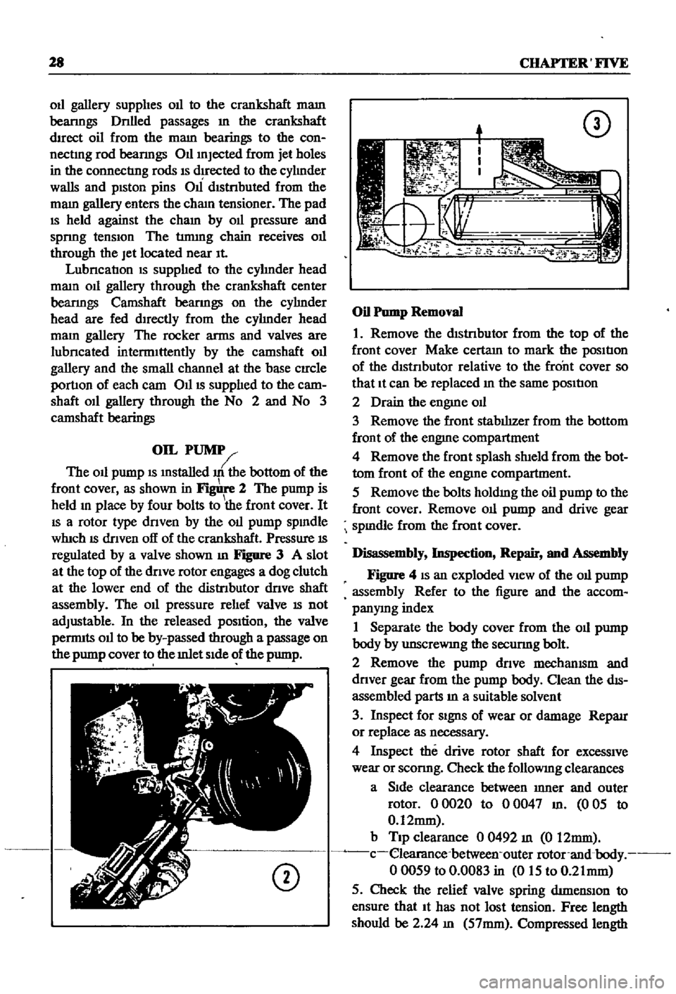
The
011
pump
IS
mstalled
m
the
bottom
of
the
front
cover
as
shown
in
2
The
pump
is
held
m
place
by
four
bolts
to
the
front
cover
It
IS
a
rotor
type
dnven
by
the
011
pump
spmdle
whIch
IS
dnven
off
of
the
crankshaft
Pressure
IS
regulated
by
a
valve
shown
m
Figure
3
A
slot
at
the
top
of
the
dnve
rotor
engages
a
dog
clutch
at
the
lower
end
of
the
distnbutor
dnve
shaft
assembly
The
011
pressure
rehef
valve
IS
not
adjustable
In
the
released
pOSition
the
valve
pernnts
011
to
be
by
passed
through
a
passage
on
the
pump
cover
to
the
mlet
Side
of
the
pump
CD
CD
Oil
Pump
Removal
1
Remove
the
dIStnbutor
from
the
top
of
the
front
cover
Make
certam
to
mark
the
posItIon
of
the
dtstnbutor
relative
to
the
front
cover
so
that
It
can
be
replaced
m
the
same
posItIon
2
Drain
the
engme
od
3
Remove
the
front
stabIhzer
from
the
bottom
front
of
the
engme
compartment
4
Remove
the
front
splash
shIeld
from
the
bot
tom
front
of
the
engine
compartment
5
Remove
the
bolts
holdmg
the
oil
pump
to
the
front
cover
Remove
011
pump
and
drive
gear
spmdle
from
the
front
cover
Disassembly
Inspection
Repair
and
Assembly
Figure
4
IS
an
exploded
VIew
of
the
011
pump
assembly
Refer
to
the
figure
and
the
accom
panymg
index
1
Separate
the
body
cover
from
the
011
pump
body
by
unscreWIng
the
secunng
bolt
2
Remove
the
pump
dnve
mechamsm
and
dnver
gear
from
the
pump
body
Clean
the
dIS
assembled
parts
m
a
suitable
solvent
3
Inspect
for
Signs
of
wear
or
damage
Reparr
or
replace
as
necessary
4
Inspect
the
drive
rotor
shaft
for
excessive
wear
or
sconng
Check
the
followmg
clearances
a
Side
clearance
between
mner
and
outer
rotor
00020
to
00047
m
005
to
0
12mm
b
Tip
clearance
0
0492
m
0
12mm
c
elearance
between
outer
rotor
and
body
00059
to
0
0083
in
015
to
0
21mm
5
Check
the
relief
valve
spring
dtmenslOn
to
ensure
that
It
has
not
lost
tension
Free
length
should
be
2
24
m
57mm
Compressed
length
Page 59 of 252
54
CHAP1ER
SIX
2
Set
the
valve
spnng
seat
m
position
on
the
top
of
the
block
and
over
the
valve
stem
3
Place
the
oil
seal
over
the
valve
stem
4
Place
the
mner
and
outer
valve
spnngs
over
the
valve
stem
S
Place
the
spnng
retamer
over
the
springs
compress
spnngs
With
spring
compressor
Figure
55
and
mstall
valve
collets
around
valve
stem
so
that
they
lock
onto
stem
6
Release
spnng
compressor
If
collets
are
firm
ly
locked
onto
the
groove
m
the
valve
stem
assembly
IS
complete
7
Install
the
rocker
guIde
on
top
of
the
valve
stem
when
assemblmg
the
rocker
pivot
assembly
VaIve
Rocker
Pivot
Assembly
1
Thread
lock
nut
onto
valve
rocker
pivOt
and
place
rocker
retaIner
over
the
valve
rocker
pivOt
2
Thread
the
above
assembly
mto
the
rocker
bushIng
protrudIng
from
the
head
Camshaft
Assembly
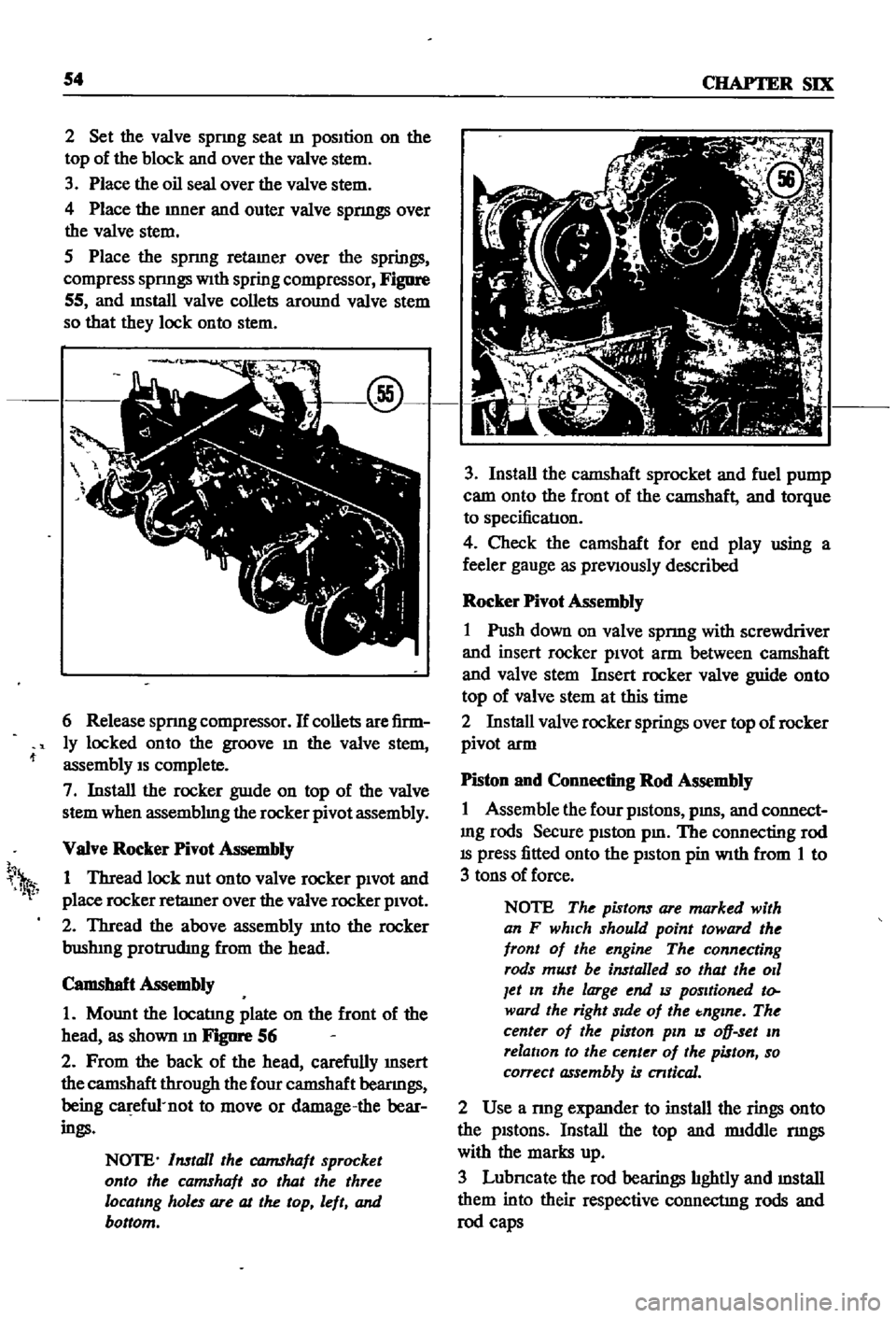
1
Mount
the
locatIng
plate
on
the
front
of
the
head
as
shown
m
FJgIlI
1
56
2
From
the
back
of
the
head
carefully
InSert
the
camshaft
through
the
four
camshaft
beanngs
being
ca
efu1
not
to
move
or
damage
the
bear
ings
NOTE
Install
the
CQJ7IShaft
sprocket
onto
the
camshaft
so
that
the
three
locating
holes
are
at
the
top
left
and
bottom
h
1
3
Install
the
camshaft
sprocket
and
fuel
pump
cam
onto
the
front
of
the
camshaft
and
torque
to
specificatIon
4
Check
the
camshaft
for
end
play
using
a
feeler
gauge
as
preViously
described
Rocker
Pivot
Assembly
1
Push
down
on
valve
spnng
with
screwdriver
and
insert
rocker
piVOt
arm
between
camshaft
and
valve
stem
Insert
rocker
valve
guide
onto
top
of
valve
stem
at
this
time
2
Install
valve
rocker
springs
over
top
of
rocker
pivot
arm
Piston
and
Connecting
Rod
Assembly
1
Assemble
the
four
pistons
pms
and
connect
mg
rods
Secure
piston
pm
The
connecting
rod
IS
press
fitted
onto
the
pISton
pin
With
from
1
to
3
tons
of
force
NOTE
The
pistons
are
marked
with
an
F
which
should
point
toward
the
front
of
the
engine
The
connecting
rods
must
be
installed
so
that
the
011
Jet
In
the
large
end
IS
positioned
to
ward
the
right
Side
of
the
tnglne
The
center
of
the
piston
pin
IS
oD
set
In
relation
to
the
center
of
the
piston
so
correct
assembly
is
cntical
2
Use
a
nng
expander
to
install
the
rings
onto
the
pistons
Install
the
top
and
rmddle
nngs
with
the
marks
up
3
Lubncate
the
rod
bearings
hghtly
and
mstall
them
into
their
respective
connectIng
rods
and
rod
caps
Page 61 of 252
56
CHAPTER
SIX
NOTE
Lubncate
the
cylinder
walls
with
new
engine
oil
prior
to
insertIOn
of
pistOns
Make
certain
that
the
ring
gaps
are
not
In
line
wIth
one
another
Place
the
gaps
180
degrees
from
each
other
and
not
posltloned
either
front
to
back
or
dIrectly
in
line
with
the
piston
pIns
CAUTION
Use
extreme
care
when
Inserting
pzs
tons
so
as
to
avoId
crankshaft
damage
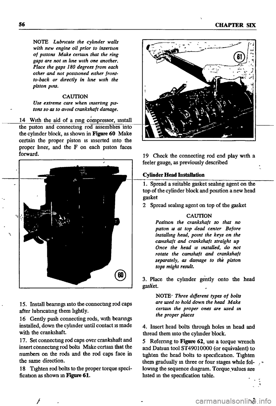
14
With
the
aid
of
a
nng
compressor
illStaIl
the
pISton
and
connectmg
rod
assembhes
into
the
cyhnder
block
as
shown
in
Figure
60
Make
certain
the
proper
piston
IS
mserted
mto
the
proper
hner
and
the
F
on
each
pISton
faces
forward
@
15
Install
beanngs
mto
the
connectIng
rod
caps
after
lubncatmg
them
hghtly
16
Gently
push
connecting
rods
With
beanngs
installed
down
the
cyhnder
until
contact
IS
made
with
the
crankshaft
17
Set
connectIng
rod
caps
over
crankshaft
and
insert
COnnectIng
rod
bolts
Make
certam
that
the
numbers
on
the
rods
and
the
rod
caps
face
in
the
same
direction
18
Tighten
rod
bolts
to
the
proper
torque
speci
ficatIon
as
shown
m
Figure
61
I
J
@v
N
i
19
Check
the
connecting
rod
end
play
With
a
feeler
gauge
as
previously
described
Cylinder
Head
Installation
1
Spread
a
suitable
gasket
seahng
agent
on
the
top
of
the
cylinder
block
and
position
a
new
head
gasket
2
Spread
seahng
agent
on
top
of
the
gasket
CAUTION
PositIon
the
crankshaft
so
that
no
pzston
IS
at
top
dead
center
Before
installing
head
point
the
keys
on
the
camshaft
and
crankshaft
straight
up
Once
the
head
zs
Installed
do
not
rotate
the
camshaft
and
crankshaft
separately
as
damage
to
the
piston
tops
might
result
3
Place
the
cyhnder
gently
onto
the
head
gask
et
NOTE
Three
dIfferent
types
of
bolts
are
used
to
hold
down
the
head
Make
certain
the
proper
ones
are
used
In
the
proper
places
4
Insert
head
bolts
through
holes
ill
head
and
thread
them
mto
the
cyhnder
block
5
Refemng
to
Figure
62
use
a
torque
wrench
and
Datsun
tool
ST49010000
or
equivalent
to
tIghten
the
head
bolts
to
specIficatIon
Tighten
them
gradually
m
three
or
four
stages
wlnle
fol
lOWIng
the
sequence
diagram
Torque
values
are
hsted
m
the
specIfication
table
Page 63 of 252
58
CHAPTER
SIX
Notch
for
t1mmg
check
Camshaft
locatmg
hole
Timmg
mark
11
Should
none
of
the
above
adjustments
be
adequate
return
the
camshaft
sprocket
to
the
No
1
hole
and
replace
the
Oll
pump
cam
and
bolt
Under
these
conditIons
the
cham
must
be
replaced
Front
Cover
Crankshaft
Polley
And
Water
Pomp
InstaDation
1
Press
a
new
Oll
seal
into
the
front
cover
2
Apply
gasket
seahng
compound
to
both
sides
of
the
left
hand
and
nght
hand
front
cover
gaskets
Mount
the
gaskets
and
front
cover
to
the
block
With
bolts
and
lockwashers
Check
the
seal
of
the
head
gasket
at
the
top
of
the
front
cover
Make
certam
to
attach
bolts
at
that
locatlon
3
Insert
woodruff
key
into
crankshaft
and
slide
crankshaft
pulley
onto
crankshaft
4
Install
crankshaft
bolt
and
washer
then
torque
as
per
the
speclficatlon
table
5
Coat
water
pump
gasket
on
both
sides
With
gasket
compound
and
mount
the
water
pump
to
the
front
cover
as
shown
m
Figure
67
Oil
Pump
Installation
1
With
No
1
cyhnder
at
top
dead
center
on
Its
compressIOn
stroke
mstall
the
packing
for
the
Oll
pump
and
distnbutor
dnve
spmdle
mto
the
front
cover
2
Install
the
Oll
pump
and
distnbutor
drive
spmdle
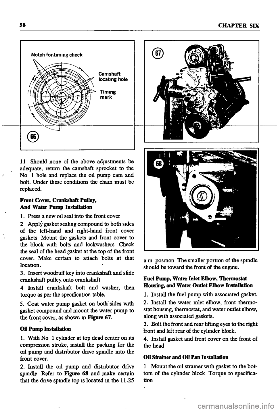
Refer
to
Figure
68
and
make
certain
that
the
dnve
spmdle
top
IS
located
m
the
11
25
@
a
m
position
The
smaller
portion
of
the
spmdle
should
be
toward
the
front
of
the
engme
Fuel
Pomp
Water
Inlet
Elbow
lbermostat
Housing
and
Water
Outlet
Elbow
InstliJIation
1
Install
the
fuel
pump
with
associated
gasket
2
Install
the
water
mlet
elbow
front
thermo
stat
housmg
thermostat
and
water
outlet
elbow
along
With
associated
gaskets
3
Bolt
the
front
and
rear
hftmg
eyes
to
the
right
front
and
left
rear
of
the
cyhnder
block
4
Install
gasket
and
front
cover
on
the
front
of
the
head
Oil
Strainer
and
Oil
Pan
Installation
1
Mount
the
011
stramer
With
gasket
to
the
bot
tom
of
the
cyhnder
block
Torque
to
specifica
tion
Page 99 of 252
94
CHAPTER
NINE
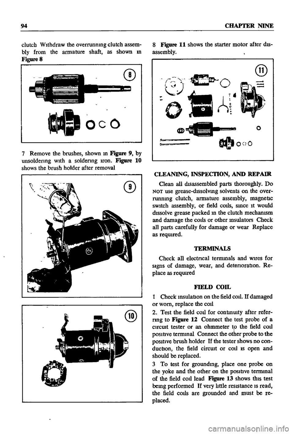
clutch
WIthdraw
the
overrunnmg
clutch
assem
bly
from
the
armature
shaft
as
shown
m
Figure
8
C
J
oeo
CD
7
Remove
the
brushes
shown
m
Figure
9
by
unsoldenng
wIth
a
soldenng
Iron
Figure
10
shows
the
brush
holder
after
removal
CD
@
8
Figure
11
shows
the
starter
motor
after
dIS
assembly
@
O
oIlA
@
O@I
coO
o
r
CLEANING
INSPECI10N
AND
REPAIR
Clean
all
dISassembled
parts
thoroughly
Do
NOT
use
grease
dISsolVIng
solvents
on
the
over
runnmg
clutch
armature
assembly
magnetIc
sWItch
assembly
ot
field
colis
SInce
It
would
dIssolve
grease
packed
In
the
clutch
mechanISm
and
damage
the
cOIls
or
other
msulators
Check
all
parts
carefully
for
damage
or
wear
Replace
as
reqwred
TERMINALS
Check
all
electrIcal
termInals
and
WIres
for
SIgnS
of
damage
wear
and
detenoratIon
Re
place
as
reqUIred
FIELD
COIL
1
Check
InsulatIon
on
the
field
coll
If
damaged
or
worn
replace
the
coll
2
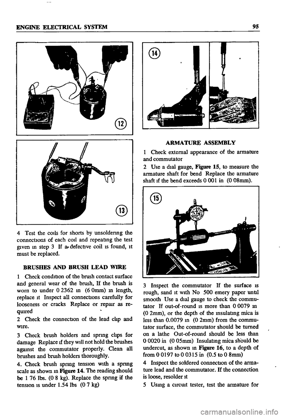
Test
the
field
coll
for
contlnulty
after
refer
rmg
to
Figure
12
Connect
the
test
probe
of
a
Clrcwt
tester
or
an
ohmmeter
t
the
field
coll
pOSItIve
termInal
Connect
the
other
probe
to
the
pOSItIve
brush
holder
If
the
tester
shows
no
con
ductIon
the
field
cirCUIt
or
coll
IS
open
and
should
be
replaced
3
To
test
for
groundmg
place
one
probe
on
the
yoke
and
the
other
on
the
pOSItIve
termmal
of
the
field
co1l1ead
Figure
13
shows
thIS
test
bemg
performed
If
very
lIttle
reSIstance
IS
read
the
field
colis
are
grounded
and
must
be
re
placed
Page 100 of 252
ENGINE
ELECI
RlCAL
SYSTEM
9S
@
@
4
Test
the
COIls
for
shorts
by
unsoldermg
the
connectIons
of
each
coIl
and
repeatlng
the
test
given
m
step
3
If
a
defectIve
coil
IS
found
It
must
be
replaced
BRUSHES
AND
BRUSH
LEAD
WIRE
1
Check
condItIon
of
the
brush
contact
surface
and
general
wear
of
the
brush
If
the
brush
is
worn
to
under
02362
In
60mm
m
length
replace
It
Inspect
all
connectIons
carefully
for
looseness
or
cracks
Replace
or
reparr
as
re
qUIred
2
Check
the
connectIon
of
the
lead
clIp
and
WIre
3
Check
brush
holders
and
sprmg
clIps
for
damage
Replace
1f
they
will
not
hold
the
brushes
agaInst
the
commutator
properly
Clean
all
brushes
aIld
brush
holders
thoroughly
4
Check
brush
sprmg
tenSIon
WIth
a
spnng
scale
as
shown
m
Figure
14
The
reading
should
be
1
76
Ibs
0
8
kg
Replace
the
spnng
if
the
tenSIon
IS
under
1
54
Ibs
0
7
kg
@
ARMATURE
ASSEMBLY
1
Check
external
appearance
of
the
armature
and
commutator
2
Use
a
dIal
gauge
Figure
15
to
measure
the
armature
shaft
for
bend
Replace
the
armature
shaft
1f
the
bend
exceeds
0
001
in
0
08mm
@
3
Inspect
the
commutator
If
the
surface
IS
rough
sand
It
With
No
500
emery
paper
untIl
smooth
Use
a
dIal
gauge
to
check
the
commu
tator
If
out
of
round
IS
more
than
00079
In
0
2mm
or
the
depth
of
the
Insulatlng
mica
is
less
than
0
0079
In
0
2mm
from
the
commu
tator
surface
the
commutator
should
be
turned
on
a
lathe
Out
of
round
should
be
less
than
o
0020
in
0
05mm
Insulatmg
mica
should
be
undercut
as
shown
m
Figure
16
to
a
depth
of
from
0
0197
to
0
0315
in
0
5
to
0
8mm
4
Inspect
the
soldered
connectIon
of
the
arma
ture
lead
and
the
commutator
If
the
connection
is
loose
resolder
It
5
Usmg
a
clrcmt
tester
test
the
armature
for
Page 102 of 252
ENGINE
ELECI
RlCAL
SYSTEM
97
No
Load
Lock
Torque
Test
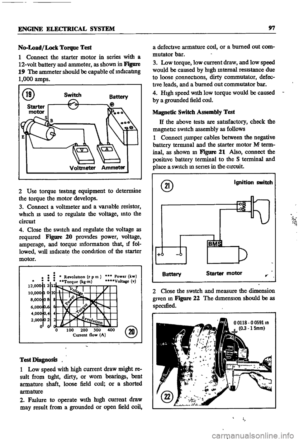
1
Connect
the
starter
motor
in
series
with
a
12
volt
battery
and
antmeter
as
shown
in
Figure
19
The
antmeter
should
be
capable
of
mdIcatIng
1
000
amps
@
Switch
Voltmeter
Ammeter
2
Use
torque
testlng
equipment
to
determine
the
torque
the
motor
develops
3
Connect
a
voltmeter
and
a
vanable
resistor
WhICh
IS
used
to
regulate
the
voltage
Into
the
circwt
4
Close
the
sWitch
and
regulate
the
voltage
as
reqUIred
Figure
20
proVIdes
power
voltage
amperage
and
torque
mformatIon
that
1f
fol
lowed
will
mdIcate
the
condItion
of
the
starter
motor
Power
kw
Voltage
v
@
Test
Diagnosis
1
Low
speed
with
high
current
draw
might
re
sult
from
tIght
dirty
or
worn
bearings
bent
armatlIre
shaft
loose
field
call
or
a
shorted
armatlIre
2
Fatlure
to
operate
With
htgh
current
draw
may
result
from
a
gromlded
or
open
field
coil
a
defectIve
armature
coll
or
a
burned
out
com
mutator
bar
3
Low
torque
low
current
draw
and
low
speed
would
be
caused
by
hIgh
Internal
reSIStance
due
to
loose
connectIons
dirty
commutator
defec
tIve
leads
and
a
burned
out
commutator
bar
4
HIgh
speed
With
low
torque
would
be
caused
by
a
grounded
field
coll
Magnetic
Switch
Assembly
Test
H
the
above
tests
are
satIsfactory
check
the
magnetIc
SWitch
assembly
as
follows
1
Connect
Jumper
cables
between
the
negative
battery
tennmal
and
the
starter
motor
M
term
inal
as
shown
In
Figure
21
Also
connect
the
positIve
battery
terminal
to
the
S
terminal
and
place
a
SWitch
m
senes
in
the
CIrCuit
@
Ignition
switch
9
I
i
j
Battery
Starter
motor
rr
2
Close
the
SWitch
and
measure
the
dimension
given
m
Figure
22
The
dimensIon
should
be
as
specIfied
o
0591m
15mm
Page 108 of 252
ENGINE
ELECTRICAL
SYSTEM
103
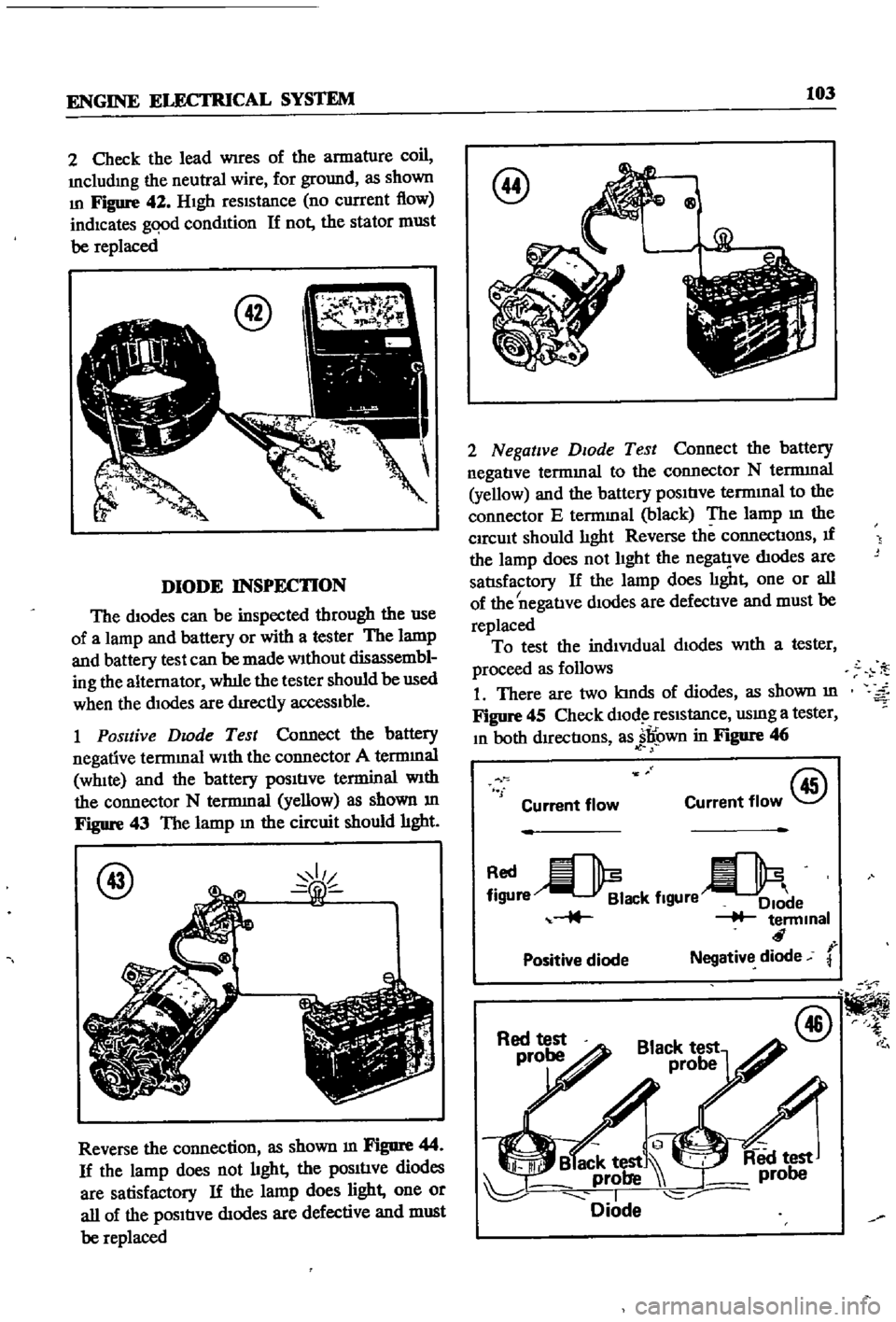
2
Check
the
lead
Wires
of
the
armature
coil
Includmg
the
neutral
wire
for
ground
as
shown
In
Figure
42
HIgh
reSIStance
no
current
flow
indicates
gqod
condItion
If
not
the
stator
must
be
replaced
DIODE
INSPECTION
The
diodes
can
be
inspected
through
the
use
of
a
lamp
and
battery
or
with
a
tester
The
lamp
and
battery
test
can
be
made
Without
disassembl
ing
the
alternator
wh1le
the
tester
should
be
used
when
the
dIodes
are
dIrectly
acceSSIble
1
Positive
Dwde
Test
Connect
the
battery
negative
terrmnal
WIth
the
connector
A
terrmnal
WhIte
and
the
battery
pOSItIve
terminal
With
the
connector
N
terrmnal
yellow
as
shown
m
Figure
43
The
lamp
m
the
circuit
should
hght
@
Reverse
the
connection
as
shown
m
Figure
44
If
the
lamp
does
not
hght
the
pOSItIve
diodes
are
satisfactory
If
the
lamp
does
light
one
or
all
of
the
pOSItIve
dIodes
are
defective
and
must
be
replaced
@
Qg
2
Negative
DIOde
Test
Connect
the
battery
negatIve
termmal
to
the
connector
N
terrmnal
yellow
and
the
battery
pOSItIve
termInal
to
the
connector
E
termmal
black
The
lamp
m
the
CIrcUit
should
lIght
Reverse
the
connectIons
If
the
lamp
does
not
lIght
the
nega1
ve
dIodes
are
satlsfactory
If
the
lamp
does
lIght
one
or
all
I
of
the
negatIve
dIodes
are
defectIve
and
must
be
replaced
To
test
the
indiVIdual
dIodes
With
a
tester
proceed
as
follows
1
There
are
two
kInds
of
diodes
as
shown
m
Figure
45
Check
dlOd
reSIstance
usmg
a
tester
In
both
dIrectIons
as
jl
own
in
Figure
46
f
Current
flow
@
Current
flow
re
ack
flgUre
e
terminal
r
Positive
diode
Negative
diode
@