1967 CHEVROLET CAMARO fuel
[x] Cancel search: fuelPage 575 of 659

ELECTRICAL-BODY AND CHASSIS 12-63
R.H. COURTESY
LP,
(67 MODELS &
16600 ONLY)
•18Y
R. H. DOOR JAMB
SW
(ALL EXCEPT 15300-400)
BK.
NEU.
LP.SW.SAF.SW.
(RJ»JD^
20 OR
20 OR
COMPT
(U*INST. PANEL COMP. LAMP
R-i3r
(ALL EXCEPT 15300-400)
14BRN
18
LBL
18 OR
14 OR
HEATER
CONTROL
LP.
RADIO CONN.
CIG.
LGT
20
P —
4
PPL
20
LG'
14 PPL—
NSOLE
CONN.
(16700-800
ONLY)
CONSOLE
CONN.
(16700-800
ONLY)
12
PPL
14 OR
12 PPL/W
20
GY/B
20 OR
14 OR
20 OR
14 OR
20 OR
20DBL
20 OR
20
GY
INSTRUMENT
CLUSTER
-ILLUM
-ILLUM
-R.H.
S
-GEN
-OILP
-ILLUM
-ILLUM
20 GY
20 GY
20DBI
20DBL/W
18
W
16BRN
-CLOCK-—:(i??T0°)
-ILLUM
^™LY
18
B
18
DBL
18
LBL
-HIGH BEAM—(11
-ILLUM
-
FUEL-GAGE —{30
-ILLUM
-ILLUM-^
-PARK BRAKE
ALARM & BRAKE
WARN. LIGHT
-ENG TEMP.—(35),
(39
-L.H.
SIG.
LAMP—(14
-ILLUM
-
TRAFFIC
HAZARD
SW.
20
LBL
20
P
16BRN
20
LG
20
PPL
14
LBL
20
T
20 OR
20 DG
20 OR
20
t
20 DG
20
Y
20
LG
20
BRN
12
PPL
PARK BRAKE
SW.
20 DBL/W
20 DG
12R
20 DG
10 OR
12
GY
20 OR
18
W
18
W
14
LBL
14T/W
14
B
SW.
67
MOD ONLY
L.H. COURT
LP.
(67 MODELS
&
16600 ONLY)
18 W-'
T/G WINDOW
SW.
(45 MOD ONLY)
DOOR JAMB
SW.
(ALL EXCEPT 15300-400)
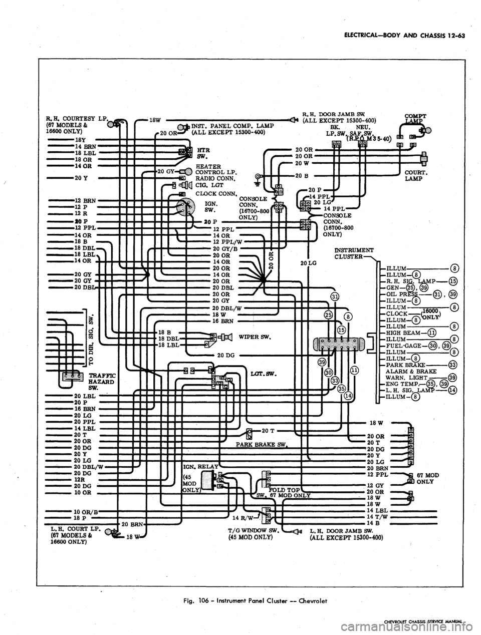
Fig.
106 - Instrument Panel Cluster ~ Chevrolet
CHEVROLET CHASSIS SERVICE MANUAL
Page 581 of 659

ELECTRICAL-BODY
AND
CHASSIS
12-69
PICK-UP DEL.
AND
STATION WAGON
•20
BRN-
•20 DG
-
SEDAN AND CONVERTIBLE
•20
DG'
20
BRN
R.H. TAIL STOP
&
DIR. SIG.
LP.
R.H. BACKING
LP.
I I
80 ONLY
I
18 LG
DOME
LP
ss
R.H. TAIL STOP
&
DIR.
SIG.
LP.
R.H. BACKING
LP.
I I
DOMELP
35 ONLY
ALL EXC.
/
LIC
LP
18
BRN-^
GROMMET
•18
BRN-
LICLP
I
FUEL
MTR
8*
I •
f—I
I FUEL
MTR
H|-18
B
L.H. BACKING
LP.
18 LG.-
20
LG
•20
BRN'
GROMMET
18
B
I
t
L.H. TAIL STOP
&
DIR.
SIG.
LP.
I I
I
L.H.
BACKING
LP.
20 LG—El
W 18 LG
•
I
'20
BRN
L.H. TAIL STOP
&
DIR.
SIG.
LP.
I I I I
III I
-BODY HARNESS
BRN
20
LG1
.20
Y-
•20 DG
13-20
OR-
3^20
W
——'
JJ
LEGEND
—
CHEVROLET WRG
— —
FBHER
BODY
WRG
— —
CHEVROLET
RPO
WRG
0
Fig.
112 -
Body
and
Rear Lighting
—
Cheveile
CHEVROLET CHASSIS SERVICE AAANUAL
Page 585 of 659

ELECTRICAL-BODY AND CHASSIS 12-73
R.H. DR .
JAMBSw'
R.H. TAIL, STOP,
&DIRSIGLP
LEGEND
—— CHEVROLET WRG
— — FISHER BODY WRG
mm. mm.
mm
CHEVROLET RPO WRG
DOMELP
FUEL
MTR
BRN
R.H. BK-UP LP
I I
/-GROM
UC LP
o
ooeo
(STA WAG)
STAWAG
\
SEDAN ONLY-
(STA WAG ONLY) g
I I I
L.H. BK-UP LP
20LG ©
•20BRN
•20Y
K,
L.H. TAIL, STOP
&DIRSIGLP
WAG
Fig.
116 - Body and Rear Lighting — Chevy II
CHEVROLET CHASSIS SERVICE MANUAL
Page 588 of 659

ELECTRICAL-BODY AND CHASSIS 12-76
20 OR
•431 INST. COMPT. LAMP&SW.
14 B
«3@H}U
EMM RADIO CONN.
HEATER SW.
-12 PPL
CLOCK
CLOCK LAMPS
HEATER CONT. LP.
20 GY
14LBL
14 BRN
14 Y
14 o:
14
OR
20 OR
20 B
12 R BAT.
12 P
12 P IGN.
12 PPL SOL.
12BRNAC
20 GY
GY
20 GY
14 OR
12 BRN
12 R
12 R
14 BRN-*
12 BRN—
20 DG
TRAFFIC HAZARD SW.
666SSSB
20DBL
20LBL
20 T
HORN
CONTACT
16B/W
20 LG
18 P
12 R
18 GY/DBL/B
20 B
14
OR
14 LBL
16 B
20
W
12 R
^
18
LBL
14 LBL
20 PP
18 OR
20 BRN
16
DG
IGNTTION SWITCH
GROUND
IGNITION LAMP
INST. LAMP
RADIO CAPACITOR CONN.
TEMP. GAGE
INST. LAMP
INST. LAMP
H. DIR. SIG. LAMP
INST. LAMP
CIGARETTE
SI
"MW LIGHTER & LAMP
INST. LAMP
CLUSTER GROUND
LAMP TELL-TALX LAMP
HI-BEAM LAMP
INST. LAMP
PARK ALARM LAMP
INST. LAMP
W/S WIPER
SWITCH
AMMETER
H. DIR. SIG. LAMP
INST. LAMP
FUEL GAGE
LIGHT SWITCH
-20 P
Fig.
119 - Instrument Panel & Cluster ~ Corvette
CHEVROLET CHASSIS SERVICE MANUAL
Page 589 of 659

ELECTRICAL-BODY
AND
CHASSIS
12-77
FUEL GAGE
LEGEND
CHEVROLET WRG
—CHEVROLET RPO WRG
DOME LAMP
REAR COMPARTMENT
LAMP (CONVERT.)
PRK BRAKE
ALARM SW
18
W
-
18 OR-
18 T —
18 BRN
BODY CONNECTOR
18 LG ——•
18 DG —
18 Y
18 P
16 B
R.H* TAIL,STOP
&
DIR, SIG.
LAMP (OUTBOARD)
R.H. TAIL, STOP
&DIR.
sia
LAMP ONBOARD)
R.B.
BACK-UP
LAMP
LICENSE LAMP
L.H. BACK-UP
LAMP
L.H,TAIL, STOP
6 DIR. SIG.
LAMP ONBOARD)
L.R. TAIL.STOP
& DIR. SIG. LAMP
(OUTBOARD)
Fig.
120 - Body and Rear Lighting — Corvette
CHEVROLET CHASSIS SERVICE MANUAL
Page 592 of 659

ELECTRICAL-BODY AND CHASSIS 12-80
L.H. DOOR
JAMBSW
— —20Y
20QR
«
«t5§ COMPT LP
RADIO
HEAT .
CONTROL SW
HEAT CONTROL
LIGHT
CJG LIGHTER
14OR
20GY
20GY
•ONLY WIRES
PERTINENT
TO PRODUC-
TION OR NEU-
TRAL SAFETY
HAVE BEEN
SHOWN.
20T—
20P —
20P —
18DBL
20LBL
20T
12PPL
20LBL
20 T
14 OR
16BRN
20DBL
20 W
18LBI
18DBL
20LG
20DG
20 DG
20BRN
20OR
20PPL
14LBL
14OR
48LBL
18B
18DBL
R.H. DOOR
JAMBSW
•INSTRUMENT
CLUSTER
ILLUM <8)
BRAKE ALARM (33-39)
R.H. SIGLAMP(15)
GEN WARN. LAMP (25-39)
ILLUM (8)
ILLUM (8)
FUEL GAGE (39-30)
OIL PRESS. WARN. (31-39)
L.H. SIGLAMP (14) .
ENG TEMP WARN. LP (35-39)
ILLUM (8)
HIGH BEAM LAMP
LIGHT
SW "
W/S WIPER
SW
BODY HARNESS
Fig.
123 - Instrument Panel and Cluster - Camaro
CHEVROLET CHASSIS SERVICE MANUAL
Page 602 of 659

SECTION 14
INDEX
Page
General Description—Chevrolet 14-1
Service Operations 14-1
Front Bumper Assembly 14-1
Removal 14-1
Disassembly . 14-1
Assembly „ 14-1
Installation . . 14-1
Bear Bumper Assembly 14-2
Removal .' 14-2
Disassembly . 14-2
Assembly 14-2
Installation 14-2
General Description—Chevelle 14-2
Service Operations 14-2
Front Bumper Assembly 14-2
Removal 14-2
Disassembly 14-3
Assembly 14-3
Installation 14-3
Rear Bumper Assembly 14-3
Removal . . 14-3
Disassembly 14-3
Assembly . . . . 14-3
Installation 14-3
General Description—Chevy II 14-3
Service Operations 14-3
Front Bumper Assembly 14-3
Removal 14-3
Page
Disassembly 14-4
Assembly 14-4
Installation . 14-4
Rear Bumper Assembly . 14-4
Removal 14-4
Disassembly 14-4
Assembly ..................... 14-4
Installation 14-4
General Description—Corvette 14-4
Service Operations . 14-4
Front Bumper Assembly . . 14-4
Removal 14-4
Installation . . 14-5
Rear Bumper Assembly 14-5
Removal 14-5
Installation 14-5
General Description—Camaro 14-6
Service Operations . 14-6
Front Bumper Assembly 14-6
Removal. . 14-6
Disassembly 14-6
Assembly 14-6
Installation 14-6
Rear Bumper Assembly 14-6
Removal . 14-6
Disassembly 14-6
Assembly 14-6
Installation 14-7
GENERAL DESCRIPTION-CHEVROLET
The front bumper is a new, full width, three-piece
design consisting of a center and two end face bars.
Two holes are pierced in the center face bar for the
parking lamps. The bumper attaching brackets are
lengthened to attach in common with new front bumper
diagonal braces.
The rear bumper is a new three-piece design similar
in general appearance to the 1966 design. Caprice mod-
els have pierced holes in the center portion of the bumper
for the back-up lamps with the other models incorporat-
ing the back-up, lamps with the tail lamps. The fuel tank
filler door assembly remains the same as the 1966
models.
SERVICE OPERATIONS
FRONT BUMPER ASSEMBLY (Fig. 1)
Removal
1.
Raise and support front end of vehicle.
2.
Disconnect parking lamp wiring.
3.
Remove bolts attaching bumper brackets and braces
to frame.
4.
Remove bumper from vehicle.
Disassembly
1.
Remove bolts attaching brackets and braces to
bumper.
2.
Separate face bar sections by removing two bolts at
each joint.
3.
Remove screws attaching each parking lamp assem-
bly to center face bar and remove parking lamps.
Assembly
Attach both parking lamps to center face bar and
tighten bolts firmly. Assemble the front bumper follow-
ing the disassembly procedure in reverse order. Except
for parking lamp attachments, install all bolts loosely; do
not tighten any bolts until all bolts are installed.
Installation
1.
Position assembled bumper on frame horns aligning
holes in bumper brackets and braces with those in
frame.
2.
Install bolts, lock washers, and nuts; do not tighten.
Note that eight sided adjustment washers (fig. 1) are
CHEVROLET O-
SERVICE
Page 622 of 659

ACCESSORIES 15-13
SYSTEM TEST
CHECKS AND ADJUSTMENTS
Automatic Level Control Test Gauge (Fig. 15)
A complete system test includes on and off-the-car
component tests.. '
On the car tests are:
Quick check of Automatic Level Control System
Compressor output test
Regulator test and adjustment
Control valve test
Time delay test
Line and fitting leak test
Trim adjustment
Off-the-car operations include:
Control valve replacement
Compressor repair
Component leak tests
a. Compressor, reservoir, and regulator
b.
Control valve
c. Superlifts
Quick Check-On Car (Reservoir Pressure at 150 PSI)
1.
Fill the fuel tank or simulate at the rate of 6 lbs./
gal.
- otherwise car should be empty.
2.
Turn engine off.
3.
Add a 2 passenger load to the rear bumper or tail-
gate.
Maintain the load until the -car lifts or AT
LEAST 20 SECONDS.
4.
After car lifts remove the load and observe until the
car lowers.
FILL VALVE
J-21999
CONNECTORS
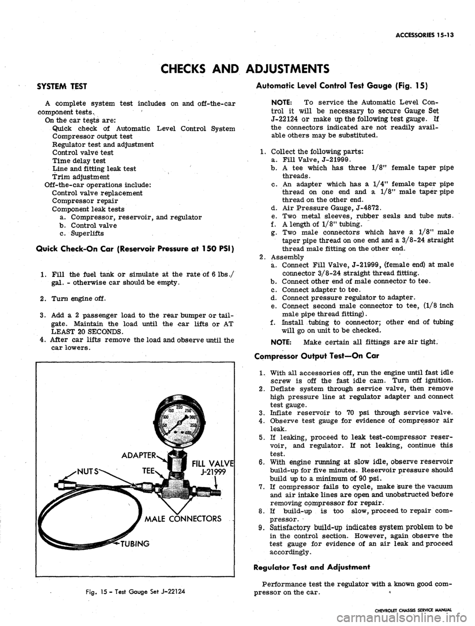
Fig.
15 - Test Gauge Set J-22124
NOTE: To service the Automatic Level Con-
trol it will be necessary to secure Gauge Set
J-22124 or make up the following test gauge. If
the connectors indicated are not readily avail-
able others may be substituted.
1.
Collect the following parts:
a. Fill Valve, J-21999.
b.
A tee which has three 1/8M female taper pipe
threads.
c. An adapter which has a 1/4" female taper pipe
thread on one end and a 1/8" male taper pipe
thread on the other end.
d. Air Pressure Gauge, J-4872.
e. Two metal sleeves, rubber seals and tube nuts.
f. A length of 1/8" tubing. ~
g. Two male connectors which have a 1/8" male
taper pipe thread on one end and a 3/8-24 straight
thread male fitting on the other end.
2.
Assembly
a. Connect Fill Valve, J-21999, (female end) at male
connector 3/8-24 straight thread fitting.
b.
Connect other end of male connector to tee.
c. Connect adapter to tee.
d. Connect pressure regulator to adapter.
e. Connect second male connector to tee, (1/8 inch
male pipe thread fitting).
f. Install tubing to connector; other end of tubing
will go on unit to be checked.
NOTE:
Make certain all fittings are air tight.
Compressor Output Test—On Car
1.
With all accessories off, run the engine until fast idle
screw is off the fast idle cam. Turn off ignition.
2.
Deflate system through service valve, then remove
high pressure line at regulator adapter and connect
test gauge.
3.
Inflate reservoir to 70 psi through service valve.
4.
Observe test gauge for evidence of compressor air
leak.
5.
If leaking, proceed to leak test-compressor reser-
voir, and regulator. If not leaking, continue this
test.
6. With engine running at slow idle, observe reservoir
build-up for five minutes. Reservoir pressure should
build up to a minimum of 90 psi.
7.
If compressor fails to cycle, make sure the vacuum
and air intake lines are open and unobstructed before
removing compressor for repair.
8. If build-up is too slow, proceed to repair com-
pressor.
9. Satisfactory build-up indicates system problem to be
in the control section. However, again observe the
test gauge for evidence of an air leak and proceed
accordingly.
Regulator Test and Adjustment
Performance test the regulator with a known good com-
pressor on the car. *
CHEVROLET CHASSIS SERVICE MANUAL