1953 JEEP CJ brake light
[x] Cancel search: brake lightPage 323 of 376
'Jeep'
UNIVERSAL
SERIES SERVICE
MANUAL
P
BRAKES
SUBJECT
PAR
GENERAL.
. P-l
Brake
Maintenance P-5
Master
Cylinder.
P-2
Parking
Brake
P-3
Transmission
Brake
P-4
BRAKE SERVICE
.P-6 Bleeding Brakes P-7
Brake
Adjustments P-14
Brake
Hoses P-8
Brake
Shoe
Initial
Adjustment P-l9
Brake
Shoe Installation P-l8
Brake
Pedal Adjustment P-9
Hand
Brake.
P-10 Inspection P-17
SUBJECT
PAR
Brake
Shoe Removal P-l6
Master
Cylinder Reconditioned. . P-20
Parking
Brake
Adjustment
.P-l 1
Relining
Transmission
Brake
P-13
Relining
Wheel
Brake
P-l5
Transmission
Brake
Adjustment .P-12
Wheel
Brake
Units P-14
Wheel
Cylinder Reconditioning P-21
TROUBLESHOOTING
P-2 2 Squeaky Brakes P-23
Rattles in Brakes P-24
SERVICE
DIAGNOSIS.
P-25
SPECIFICATIONS
P-2 6
P-1. GENERAL
A
double-safety
hydraulic brake system in con
junction with self-adjusting wheel brake units are
standard
equipment on all current production
'Jeep* vehicles. The
double-safety
brake system
Is
equipped with dual
stop
light switches that op
erate independently of each other, thus eliminating
possible
stop
light failure. Service information for
self adjusting brakes starts with Par. P-14.
All
four-wheel-drive vehicles are equipped with a transmission brake that operates in the drive line
and
is mounted to the rear of the transfer case. Two-wheel-drive vehicles
(DJ-5,
DJ-6)
are equipped
with a hand-operated parking brake that operates at the rear wheels.
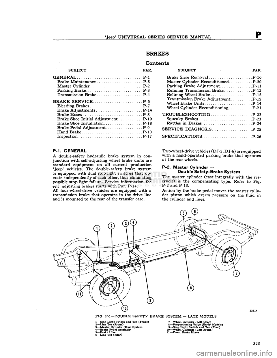
P-2.
Master Cylinder —
Double Safety-Brake System
The
master cylinder (cast integrally with the res
ervoir)
is the compensating type. Refer to Fig.
P-2 and P-13.
Action by the brake pedal
moves
the master cylinder piston which exerts pressure on the fluid in
the cylinder and lines. 12914
FIG.
P-l—DOUBLE SAFETY BRAKE SYSTEM —
LATE
MODELS 1— Stop Light Switch and Tee (Froat)
2—
Line
Tee (Front)
3—
Master
Cylinder (Dual System
4—
Brake
Pedal Assembly 5—
Brake
Hose
6—
Line
Tee
(Rear)
7—
Wheel
Cylinder (Left
Rear)
8— Proportioning Valve
(Early
Models)
9— —Stop Light Switch and Tee
(Rear)
10—
Wheel
Cylinder (Left Front)
11—
Front
Brake
Hoses
323
Page 324 of 376
p
BRAKES
13264
FIG- P-2—DOUBLE
SAFETY BRAKE
MASTER
CYLINDER
With
the Double-Safety brake system type master
cylinder,
failure
in one part of the brake system
does
not result in
failure
of the entire hydraulic
brake system. Failure in the
front
brake system
will
leave the rear brake system
still
operative or
failure
in
the rear system
will
leave the
front
brake system
operative.
A
double hydraulic
cylinder
with
two outlets, two
residual
check valves, two
fluid
reservoirs, and
two
hydraulic pistons (a
primary
and secondary)
are operated in tandem by a single hydraulic push
rod.
The
primary
outlet is connected to the
front
brakes
with
the secondary outlet connected to the rear brakes.
With
the master
cylinder
fluid
reservoirs
filled
and the
front
and rear brake system
bled,
there is a
solid
column
of
fluid
on the
forward
side of both the
primary
and the secondary pistons.
Upon
application
of the brakes, through movement
of
the brake pedal,
fluid
is displaced by the pistons
into
the wheel cylinders to activate both
front
and
rear brakes.
Upon
release
of the brakes,
fluid
re
turns
from
the rear wheel cylinders through the secondary residual check valve to the secondary
portion
of the master
cylinder
bore.
Fluid
also
returns
from
the
front
wheel cylinders through the
primary
residual check valve to the
primary
portion
of the master
cylinder
bore.
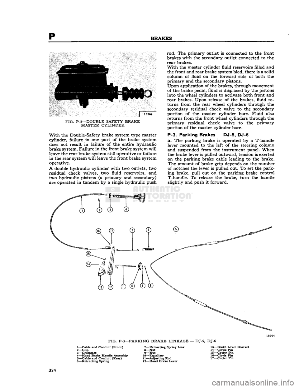
P-3.
Parking
Brakes
— DJ-5, DJ-6
a.
The parking brake is operated by a T-handle
lever
mounted to the
left
of the steering
column
and
suspended
from
the instrument panel. When
the brake lever is
pulled
outward, tension is exerted
on
the parking brake cable leading to the brake.
The
amount of brake
grip
depends
on the number
of
notches the lever is
pulled
out. To set the park
ing
brake,
pull
out on the parking brake
control
T-handle.
To
release
the brake,
turn
the handle
slightly
and push it
forward.
0
FIG.
P-3—PARKING
BRAKE LINKAGE
—
DJ-5,
DJ-6
1—
Cable
and
Conduit
(Front)
7—Retracting
Spring
Link
13—Brake
Lever
Bracket
2—
Clip
8—Nut
14—Clevis
Pin
3—
Grommet
9—Nut
15—Cotter
Pin
4—
Hand
Brake
Handle
Assembly
10—Equalizer
16—Clevis
Pin
5—
Cable
and
Conduit
(Rear)
11—Adjusting
Rod
17—Cotter
Pin
6—
Retracting
Spring
12—Hand
Brake
Lever
324
Page 327 of 376
'Jeep'
UNIVERSAL
SERIES SERVICE
MANUAL
P
lengthening of the brake master cylinder eye bolt.
This
is
done
so the primary cup
will
clear the by
pass port when the piston is in the off position,
otherwise the compensating action of the master
cylinder
for expansion and contraction of the fluid
in
the system, due to temperature changes,
will
be destroyed and cause the brakes to drag.
Note:
Some older 'Jeep' vehicles may
develop
side
movement
of the clutch and brake pedals resulting
from wear of the pedals, shafts, and bushings. One
way to
compensate
for this wear is to install a pedal
slack
adjuster kit,
Part
No.
921936.
FIG.
P-6—HAND
BRAKE
ADJUSTMENT
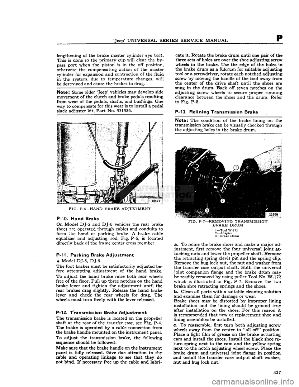
P-10.
Hand Brake
On
Model DJ-5 and DJ-6 vehicles the rear brake
shoes
are operated through cables and conduits to
form the hand or parking brake. A brake cable
equalizer and adjusting rod, Fig. P-6, is located directly back of the frame center cross member.
P-11.
Parking Brake Adjustment
•
Model DJ-5, DJ-6.
The
foot
brakes must be satisfactorily adjusted be
fore attempting adjustment of the hand brake.
To
adjust the hand brake raise both rear
wheels
free of the floor.
Pull
up three
notches
on the hand
brake
lever and tighten the adjustment until the
rear
brakes drag slightly. Release the hand brake
lever and check the rear
wheels
for drag. The
wheels
must turn freely with the lever released.
P-12.
Transmission Brake Adjustment
The
transmission brake is located on the propeller
shaft at the rear of the transfer case, see Fig. P-4.
The
brake is operated by a cable connection from
the brake handle mounted on the instrument panel.
To
adjust the transmission brake, the following
sequence
should be followed:
Make
sure that the brake handle on the instrument
panel is fully released. Give due attention to the
cable and operating linkage to see that
they
do
not bind. If necessary free up the cable and
lubri
cate it. Rotate the brake drum until one pair of the
three
sets
of
holes
are over the
shoe
adjusting screw
wheels
in the brake. Use the
edge
of the
holes
in
the brake drum as a fulcrum for suitable adjusting
tool
or a screwdriver, rotate each notched adjusting
screw by moving the handle of the
tool
away from
the center of the drive shaft until the
shoes
are
snug in the drum.
Back
off seven
notches
on the
adjusting screw
wheels
to secure proper running clearance
between
the
shoes
and the drum. Refer
to Fig. P-8.
P-13.
Relining Transmission Brake
Note:
The condition of the brake lining on the
transmission brake can be visually checked through
the adjusting
holes
in the brake drum.
FIG.
P-7—REMOVING
TRANSMISSION
BRAKE
DRUM
1— Tool W-172
2—
Adapter
3—
Brake
Drum
a.
To reline the brake
shoes
and make a major ad
justment, first remove the four universal joint at taching nuts and lower the propeller shaft. Remove
the retracting spring clevis pin and the spring clip.
Remove the hug lock nut, the nut and washer from
the transfer case output shaft. Both the universal
joint companion
flange
and the brake drum may be readily removed by using puller Tool No. W-172
which
is illustrated in Fig. P-7. Remove the two
brake
shoe
retracting springs and the
shoes.
b. Clean all parts with a suitable cleaning solution
and
examine them for damage or wear.
Brake
shoes
may be distorted by improper lining
installation and the lining should be ground true
after installation on the
shoes.
For this reason it
is recommended that new or replacement
shoe
and
lining assemblies be installed.
c. To reassemble, first turn both adjusting screw
wheels
away from the center to "all off" position.
Place a light film of grease on the brake actuating
cam
and install the
shoes.
Install the black
shoe
re
turn
spring next to the cam and the yellow spring next to the notch adjusting wheel screw. Place the
brake
drum and universal joint
flange
in position
and
install the transfer case output shaft washer,
nut and hug lock nut. 327
Page 339 of 376
'Jeep'
UNIVERSAL
SERIES
SERVICE
MANUAL
Q
ice, provide maximum safety over all
types
of
terrain,
and furnish the medium on which the
vehicle can be maneuvered with ease. Although
there are other
elements
of tire service, inflation maintenance is the most important and in many
instances the most neglected. The tire pressure should be maintained for safe operation. An under- inflated tire is dangerous as too much flexing can
cause breakage of the casing. Overinflation in time
may
cause a blowout.
Upon
careful inspection of tires, it may be found
that improper wheel alignment, balance, grabbing
brakes,
poor driving habits, fast cornering or other
conditions are the cause of wear. Such conditions
should be corrected.
a.
UNDERINFLATION
Underinflation
distorts the normal contour of the
tire
body and the tire
bulges
or "bellies out" with
an
extreme flexing action.
This
wears the tread at the
edges
more than the center and generates
excessive internal heat, weakening the cords and
resulting
in bruises, broken cords or ply separation.
Underinflation
also leads to rim bruises as in sufficient resistance is provided to prevent the tire
from
being jammed against the rim and crushed
or
cut when the tire strikes a
curb,
rock, or rut.
b.
OVERINFLATION
When
a tire is
overinf
lated,
increased tension caused by excessive pressure prevents proper deflection of
the sidewalls.
This
results in wear in the center of the tread and the tire also
loses
its ability to absorb
road
shocks. Under this increased
strain,
cords in the tread area eventually snap under impact, causing a casing break.
c.
MISALIGNMENT
WEAR
Excessive
wheel camber causes the tires to run at an angle to the road when camber is incorrect
it
will
cause excessive wear on one side of the
tire
tread.
Front
wheels should be straight ahead or toe-in slightly. When there is excessive toe-in or
toe-out,
tires
will
revolve with a side motion and scrape
the tread rubber off.
Front
tires
will
show wear on the outside with too great a toe-in condition
and
on the inside with a
toe-out
condition.
d.
BALANCE
Cupping
and bald spotting of tires is associated
with
wear on a vehicle driven mostly at high-way
speeds
without the recommended tire rotation and
with
unbalance conditions.
Q-12.
Tire
Care
Note;
For satisfactory 4-wheel drive operation, a
4-wheel drive vehicle
MUST
be equipped with the same size tires of equal circumference on all
four wheels. The tires must then be inflated to
proper
factory recommended pressures at all times.
Tire
pressure, tire rotation, wheel balance, and wheel alignment are the four vital factors that in
fluence the
extent
of tire life and the
ease
and safety of vehicle control.
Four
of the most common
tire
troubles are:
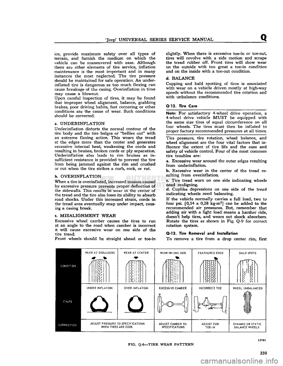
a.
Excessive wear around the outer
edges
resulting
from
underinflation.
b.
Excessive wear in the center of the tread re
sulting from overinflation.
c.
Tire
tread worn on one side indicating wheels
need realigning.
d.
Cuplike
depressions on one side of the tread
indicating
wheels need balancing.
If
the vehicle normally carries a
full
load, two to
four psi. [0,14 a 0,28 kg-m2] can be added to the
recommended air pressures. But, remember that adding air with a light load means a harsher ride,
doesn't
help tires, and wears out shock absorbers. Rotate the tires as shown in Fig. Q-9 for correct
rotation system.
Q-13.
Tire
Removal
and
Installation
To
remove a tire from a drop center rim, first
WEAR
AT SHOULDERS
WEAR
AT CENTER
WEAR
ON ONE
SIDE
FEATHERED
EDGE
BALD
SPOTS
/1TTDN
i
UNDER
INFLATION
OVER
INFLATION
EXCESSIVE
CAMBER
INCORRECT
TOE
WHEEL
UNBALANCED
liF
11
ADJUST
PRESSURE TO
SPECIFICATIONS
WHEN
TIRES ARE
COOL
ADJUST
CAMBER
TO
SPECIFICATIONS
ADJUST
FOR
TOE-IN
DYNAMIC
OR
STATIC
BALANCE
WHEELS
FIG.
Q-8—TIRE
WEAR
PATTERN
339
Page 354 of 376
T
BODY
from the windshield wiper vacuum fitting. On
late
models
disconnect electrical wires from wiper
motor. Unlatch the two windshield clamps on each
side
of the windshield.
Fold
the windshield forward
until
the
slot
in the windshield
hinges
aligns with the flat
side
of the pin in the
body
hinges.
Slip wind
shield off the pins and remove from
body.
T-4.
Windshield Glass
The
windshield
glass
is mounted in a rubber
weatherstrip which in turn
mounts
in the frame. A
rubber
locking strip, which
holds
the
glass
firmly in
the frame, is inserted in a moulded
groove
around
the rear
face
of the weatherstrip as shown in Fig.
T-2.
To remove the
glass
it is necessary to first
remove the locking strip which may be pried out
with a screwdriver or similar
tool.
Installation is,
obvious.
T-5.
Canvas Tops
Canvas
tops
are available in
Half
Tops and
Full
Tops.
Installation instructions are provided with
each canvas top kit for each model vehicle.
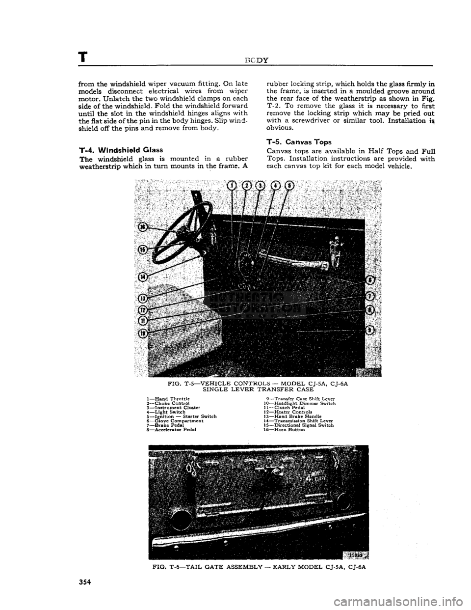
FIG.
T-5—VEHICLE CONTROLS — MODEL CJ-5A, CJ-6A
SINGLE
LEVER
TRANSFER CASE 1—
Hand
Throttle 9—Transfer Case Shift
Lever
2—
Choke
Control 10—Headlight Dimmer Switch
3— Instrument Cluster 11—Clutch Pedal 4—
Light
Switch 12—Heater Controls 5— Ignition — Starter Switch 13—Hand
Brake
Handle
6— Glove Compartment 14—Transmission Shift
Lever
7—
Brake
Pedal 15—Directional Signal Switch
8— Accelerator Pedal 16—Horn Button
FIG.
T-6—TAIL GATE ASSEMBLY —
EARLY
MODEL CJ-5A, CJ-6A
354
Page 355 of 376
'Jeep'
UNIVERSAL
SERIES
SERVICE
MANUAL
T
FIG.
T-7—TAIL
GATE
ASSEMBLY
—
LATE
MODEL
CJ-5, CJ-6
T-6.
Care
of
Fabric
Tops
Remove fabric
tops
from their protective covering
immediately after they are received. Store in a
dry,
clean,
airy
place. If the material is damp, the
top should be installed on the vehicle immediately
and
washed with a mild soap; then
give
the top a
quick
and thorough rinsing.
T-7.
Brake
and
Clutch Pedal Pads
A
clutch and brake pedal pad cover has been re leased which has a .44" [11,18 mm.]
groove
molded into the back side of the pad cover. When installing,
the grooved opening is located down and to the
bottom
of the pedal. See Fig. T-ll. The purpose of the
groove
concerns models not listed in this
manual.
The pedal pad cover formerly used is
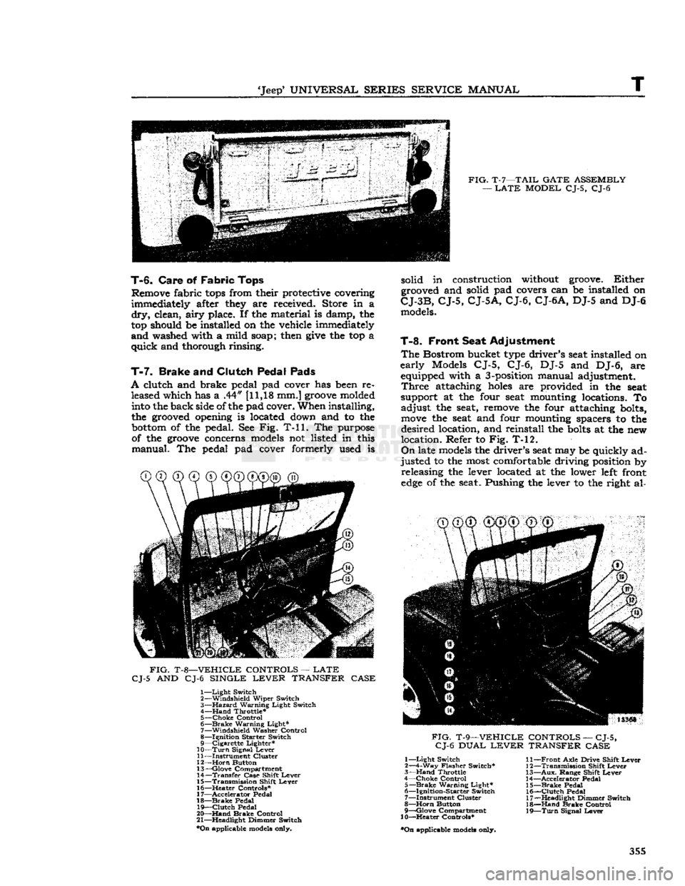
FIG.
T-8—VEHICLE
CONTROLS
—
LATE
CJ-5
AND CJ-6
SINGLE
LEVER
TRANSFER
CASE
1—
Light
Switch
2—
Windshield
Wiper
Switch
3—
Hazard
Warning
Light
Switch
4—
Hand
Throttle*
5—
Choke
Control
6—
Brake
Warning
Light*
7—
Windshield
Washer
Control
8—
Ignition
Starter
Switch
9—
Cigarette
Lighter*
10—
Turn
Signal
Lever
11—
Instrument
Cluster
12—
Horn
Button
13—
Glove
Compartment
14—
Transfer
Case
Shift
Lever
15—
Transmission
Shift
Lever
16—
^Heater
Controls*
17—
Accelerator
Pedal
18—
Brake
Pedal
19—
Clutch
Pedal
20—
Hand
Brake
Control
21—
Headlight
Dimmer
Switch
*On
applicable models only. solid in construction without groove.
Either
grooved and solid pad covers can be installed on
CJ-3B,
CJ-5,
CJ-5A,
CJ-6,
CJ-6A,
DJ-5 and DJ-6 models.
T-8.
Front Seat Adjustment
The
Bostrom bucket type driver's seat installed on
early
Models CJ-5, CJ-6, DJ-5 and DJ-6, are equipped with a 3-position manual adjustment.
Three
attaching
holes
are provided in the seat
support at the four seat mounting locations. To
adjust
the seat, remove the four attaching bolts,
move
the seat and four mounting spacers to the
desired
location, and reinstall the
bolts
at the new
location. Refer to Fig. T-12.
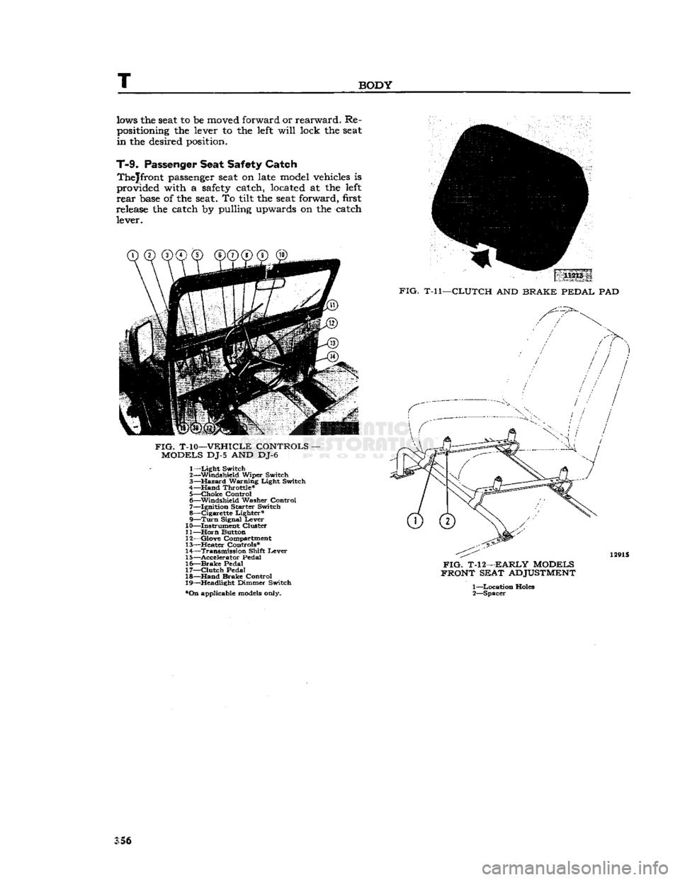
On
late models the driver's seat may be quickly ad
justed
to the most comfortable driving position by releasing the lever located at the lower left front
edge
of the seat. Pushing the lever to the right al-
CD CD®
®@©"®^
FIG.
T-9—VEHICLE
CONTROLS
—
CJ-5,
CJ-6
DUAL
LEVER
TRANSFER
CASE
1—
Light
Switch
2—4-Way
Flasher
Switch*
3—
Hand
Throttle
4—
Choke
Control
5—
Brake
Warning
Light*
6—
Ignition-Starter
Switch
7—
Instrument
Cluster
8—
Horn
Button
9—
Qlove
Compartment
10—Heater
Controls*
•On
applicable models only.
11—
Front
Axle
Drive
Shift
Lever
12—
Transmission
Shift
Lever
13—
Aux.
Range
Shift
Lever
14—
Accelerator
Pedal
15—
Brake
Pedal
16—
Clutch
Pedal
17—
Headlight
Dimmer
Switch
18—
Hand
Brake
Control
19—
Turn
Signal
Lever
355
Page 356 of 376
T
BODY
lows
the seat to be
moved forward
or
rearward.
Re
positioning
the
lever
to the
left
will
lock
the seat
in
the
desired position.
T-9.
Passenger
Seat
Safety
Catch
Thejfront
passenger seat on
late model vehicles
is
provided
with
a
safety
catch, located
at the
left
rear
base of the seat. To
tilt
the seat
forward,
first
release
the
catch
by
pulling
upwards
on the
catch lever. 11213
.
FIG.
T-ll—CLUTCH
AND
BRAKE PEDAL
PAD
FIG.
T-10—VEHICLE CONTROLS
-
MODELS
DJ-5 AND DJ-6 1—
Light
Switch
2— Windshield Wiper Switch
3—
Hazard
Warning Light Switch
4—Hand Throttle*
5—
choke
Control
6— Windshield
Washer
Control
7— Ignition
Starter
Switch
8— Cigarette Lighter* 9—
Turn
Signal Lever
10— Instrument Cluster
11—
Horn
Button
12— Glove Compartment
13—
Heater
Controls*
14— Transmission Shift Lever
15— Accelerator
Pedal
16—
Brake
Pedal
17—
Clutch
Pedal
18—
Hand
Brake Control
19— Headlight Dimmer Switch
*On
applicable
models
only.
FIG.
T-12—EARLY MODELS
FRONT SEAT
ADJUSTMENT
1—
Location Holes
2— Spacer
S5§
Page 361 of 376

'Jeep*
UNIVERSAL
SERIES
SERVICE
MANUAL
U
DESCRIPTION
—
Continued
AXLES
W-99* Gauge — Pinion & Ring
Gear
Setting
W-104-B* Puller — Tapered Roller Bearing Removing
W-126* Driver — Pinion Bearing Cup
W-128* Installer — Differential Inner Oil Seal W-129 Spreader — Differential
Carrier
Housing
W-138* Driver & Adapter —
King
Pin Bearing
W-144* Wrench — Wheel Bearing Adjusting Nut W-147* Driver — Pinion Oil Seal W-163* Puller
—-
Axle Shaft Drive Flange
W-186* Driver — Axle Shaft Oil Seal
W-188* Driver — Differential Case Bearing W-251* Puller — Pinion Oil Seal
W-262*
Sleeve
— Pinion Bearing Installing
W-263
Semi-Floating
Rear
Axle Shaft Oil Seal W-264* Driver — Pinion Outer Bearing Cup
W-297* Torque Wrench — Pinion Bearing Adjusting W-343* Remover
85
Installer —
Rear
Axle Bearing (Flanged Axle)
W-344* Installer — Pinion Inner Bearing Cups
C-319-A
Puller —
Rear
Wheel Hub (Tapered Axle Shaft)
C-690 Checking Scale —
King
Pin Bearing Preload DD-914-P Press — Tapered Roller Bearing Removing
DD-914-9 Reducer Ring — Differential & Pinion Bearings (Use with DD-914-P)
C-3
716 Driver — Differential
Carrier
Bearing C-4142
Gear
Rotating Tool —
Trac-Lok
Differential
**Jeep*
exclusive
tool
Steering
Group
C-3646 Puller, Steering Shaft Arm
Brake
Group
W-172 Puller, Parking Brake Drum
U-12.
STflNDfiRD
AND
RECOMMENDED
TOOLS
Tool
Description
ENGINE
W-292
Tester — Cooling
System
Thermostat
C-119 Indicator — Cylinder Bore C-385 Compressor — Piston Ring
C-647 Fixture — Spring Testing
C-823
Hone
— Cylinder Bore Refinishing
C-3012 Reamer — Cylinder Ridge
C-3250 Pliers — Radiator fis Heater
Hose
Wire Clamp
C-3411
Gauge — Pressure & Vacuum
C-3422-A Compressor — E-type Valve Spring
C-3501
Hone
— Cylinder
Deglazing
C-3514
Flusher — Cooling
System
C-3886 Fixture — Carburetor Holding C-3896-A Tachometer — Portable
C-3943 Gauge — Compression Checking
C-3952 Torque Wrench, 150
lb-ft.
Swivel Head C-3953 Stand, Engine Repair
C-3959 Light — Ignition Timing
C-4065 Wrench — Oil Filter Removing
C-4080 Tester — Cooling
System
fig
Pressure Cap
ELECTRICAL
40B Hydrometer — Battery Service
W-291 Tester — Instrument
C-3674
Aimers —
Headlight
(Pair)
C-3829 Tester —
Diode
Polarity
C-3888 Tester — Volt-Ampere C-3950 Tester — 12V 60 Amp. Carbon Pile Resistor 361