1953 JEEP CJ belt
[x] Cancel search: beltPage 69 of 376

'Jeep9
UNIVERSAL
SERIES
SERVICE
MANUAL
h.
Check
ignition (distributor) timing; reset if
necessary.
i.
Check
carburetor
adjustments; reset if necessary,
j.
With
engine
fully warmed up, tighten cylinder
head and manifold
bolts
and nuts to specified
torque.
Check
cylinder head gaskets and
bolts
for
air
or coolant leaks.
Note:
Tightness of cylinder head
bolts
should be
checked and corrected after 500 to 600 miles [800
a
960 km.] of normal operation.
k.
Check
fan belt tension; adjust if necessary.
I.
Check
for and correct any oil leak, fuel leak or
coolant leak.
D-107.
VALVE
ADJUSTMENT
Proper
valve adjustment is important to prevent
burning
of valves and poor
engine
performance.
This
adjustment consists of obtaining a specified
lash
in the valve mechanism. The exhaust valve
tappets and the intake valve rocker arms should be adjusted to the proper clearance with the
engine
cold (at room temperature). Valve clearance can
be properly adjusted only when the tappet is on the
heel or low portion of the cam.
INTAKE
OPENS
9°
BTC?
FIG.
D-43-
10270
-VALVE
TIMING
D-108. Valve Adjustment Procedure
The
exhaust valve tappets are adjusted by turning
the adjusting screw in or out of the tappet as neces
sary
to obtain the proper clearance. Where special
wrenches can be obtained, they should be used to facilitate the adjustment. The proper clearance is .016" [0,406 mm.]
between
the end of the adjusting
screw and the
bottom
of the exhaust valve.
Crank
the
engine
over to
close
a valve and check
the clearance with a feeler
gauge.
To adjust, hold
the tappet with one wrench and
turn
the adjusting
screw,
with the other.
Check
and adjust each of
the tappets in proper sequence.
Adjust
each intake valve by adjusting the rocker
arm
screw at the push rod to obtain .018" [0,457 mm.] clearance
between
the rocker arm and the
valve stem with tappet on the heel of the cam.
D-109.
Check
Valve
Timing
To
check the valve timing, carefully set the intake
valve rocker arm adjustment for No. 1 cylinder to .026"
[0,6604
mm.]
between
the rocker arm and the
valve stem. Rotate the crankshaft clockwise until
the piston in No. 1 cylinder is ready for the intake stroke. The intake valve
opens
9° before top center
(BTC).
Note
the distance
between
the
"TC"
and
"5°"
marks on the indicator on the timing gear
cover and estimate the 9° before top center position.
See
Fig.
D-43.
With
the crankshaft in this position, timing is correct if the rocker arm is just tight
against the intake valve stem. Do not overlook resetting the rocker arm adjustment to the correct
running
clearance.
D-110. Positive
Crankcase
Ventilation
Be
sure there are no air leaks at the tube connec
tions
between
the air cleaner and the oil filler tube,
and
that the oil filler tube cap gasket is in
good
condition. Always keep the cap locked securely in
place. When tuning the
engine
or grinding valves, remove the control valve and clean it thoroughly.
If
the valve is blocked with carbon, the ventilating
system
will
not operate and, should the valve
fail
to seat, it
will
be impossible to make the
engine
idle satisfactorily. Refer to Par. C-6 for servicing.
D-111. Oil
Filter
The
engine
is equipped with a throw-away type
oil
filter.
This
oil filter must be serviced periodi
cally
as outlined in the
Lubrication
Section. 69
Page 70 of 376

D
HURRICANE
F4
ENGINE
D-112.
SERVICE
DIAGNOSIS
Poor
Fuel
Economy Ignition Timing Slow or Spark Advance Stuck
Carburetor
Float High
Accelerator Pump Not Properly Adjusted
High
Fuel
Pump Pressure
Fuel
Leakage
Leaky
Fuel
Pump Diaphragm
Loose Engine Mounting Causing High
Fuel
Level
in
Carburetor
Low
Compression Valves Sticking
Spark
Plugs Bad
Spark
Plug Cables Bad Weak
Coil
or Condenser Improper Valve Tappet Clearance
Carburetor
Air Cleaner Dirty
High Oil Level in Air Cleaner Dragging Brakes
Front
Wheels Out of Alignment
Tires
Improperly Inflated Inaccurate Odometer
Faulty
Fuel
Tank
Cap
Clogged
Muffler or Bent Exhaust Pipe
Lack
of Power
Low
Compression Ignition System (Timing Late)
Improper Functioning Carburetor or
Fuel
Pump
Fuel
Lines
Clogged
Air
Cleaner Restricted
Engine Temperature High Improper Tappet Clearance
Sticking Valves Valve Timing Late
Leaky
Gaskets
Muffler
Clogged
Bent Exhaust Pipe
Defective
Spark Plugs—Clean or Replace
Defective
Breaker Points—Replace
Points
Incorrect Breaker Point Gap—Reset
Points
Defective
Condenser or Coil—Replace
Loose Electrical Connections—Locate and Tighten
Broken Valve Spring—Replace Spring Broken Piston or Rings—Replace
Defective
Head Gasket—Replace Gasket
Cracked
Distributor Cap—Replace Cap
Low
Compression
Leaky
Valves
Poor Piston Ring Seal Sticking Valves
Valve Spring Weak or Broken
Cylinder
Scored or Worn
Tappet Clearance Incorrect
Piston Clearance too Large
Leaky
Cylinder Head Gasket
Burned Valves and
Seats
Sticking Valves or too Loose in Guides Improper Timing
Excessive Carbon Around Valve Head and Seat Overheating
Valve Spring Weak or Broken Burned Valves and Seats—Continued
Valve Tappet Sticking
Valve Tappet Clearance Incorrect
Clogged
Exhaust System
Valves Sticking Warped Valve Improper Tappet Clearance
Carbonized or Scored Valve
Stems
Insufficient Clearance Valve Stem to Guide
Weak or Broken Valve Spring Valve Spring Cocked Contaminated Oil
Overheating Inoperative Cooling System
Thermostat Inoperative Improper Ignition Timing
Improper Valve Timing
Excessive Carbon Accumulation
Fan
Belt too Loose
Clogged
Muffler or Bent Exhaust Pipe
Oil
System Failure
Scored or Leaky Piston Rings
Popping-Spitting-Detonation
Improper Ignition
Improper Carburetion
Excessive Carbon
Deposit
in Combustion
Cham
bers
Poor Valve Seating Sticking Valves
Broken Valve Spring Tappets Adjusted too Close
Spark
Plug Electrodes Burned
Water or Dirt in
Fuel
Clogged
Lines Improper Valve Timing
Excessive Oil Comsumption Piston Rings Stuck in Grooves, Worn or Broken Piston Rings Improperly Fitted or Weak Piston Ring Oil Return
Holes
Clogged
Excessive Clearance, Main and Connecting Rod
Bearings
Oil
Leaks at Gaskets or Oil Seals
Excessive Clearance, Valve Stem to Valve Guide (Intake)
Cylinder
Bores Scored, Out-of-Round or Tapered Too Much Clearance, Piston to Cylinder Bore
Misaligned Connecting Rods
High Road
Speeds
or Temperature
Crankcase
Ventilator Not Operating
Bearing Failure
Crankshaft
Bearing Journal Out-of-Round
Crankshaft
Bearing Journal Rough
Lack
of Oil
Oil
Leakage
Dirty
Oil
Low
Oil Pressure or Oil Pump Failure
Drilled
Passages
in Crankcase or Crankshaft
Clogged
Oil
Screen Dirty Connecting Rod Bent 70
Page 75 of 376

'Jeep'
UNIVERSAL SERIES
SERVICE
MANUAL
Dl
DAUNTLESS
V-6
ENGINE
Contents
SUBJECT
PAR.
SUBJEC
GENERAL
.... . . Dl-1 Oil Pump Cl(
ENGINE DESCRIPTION
D1-2
Engine
Mounts Dl-3
ENGINE REMOVAL
Dl-4
ENGINE DISASSEMBLY
Dl-5
Alternator
and Fan Belt Dl-11
Camshaft
.... Dl-26
Cooling Fan and Water Pump.
......
.Dl-12
Crankshaft
Front Oil Seal .Dl-21
Crankshaft
Pulley D1-17
Crankshaft
Vibration Damper Dl-18
Cylinder
Head Assembly Dl-24
Distributor
Dl-9
Exhaust
Manifold .Dl-8
Flywheel
Dl-28
Flywheel
Housing and
Clutch
Dl-27
Fuel
Pump. ... . .Dl-10
Intake
Manifold and
Carburetor
Assembly.
.............
.Dl-7
Main
Bearing and Crankshaft. Dl-32 Mounting Engine on Engine Stand. . . . .Dl-6
Oil
Dipstick. Dl-16
Oil
Filter
Dl-13
Oil
Pan.. ...
.......
.Dl-29
Oil
Pressure Sending Unit Dl-15
Oil
Pump Dl-19
Oil
Pump Intake Pipe and Screen Dl-30
Piston and Rod Assembly. Dl-31
Push
Rod and Valve
Lifter.
.Dl-25
Rocker
Arm Cover Dl-23
Starter
Motor Dl-14
Timing
Chain
and Sprocket Dl-22
Timing
Chain
Cover Dl-20
ENGINE CLEANING, INSPECTION AND REPAIR
. . ... .Dl-33
Camshaft
Cleaning and Inspection Dl-55
Connecting Rod Bearing Inspection
and
Fitting .Dl-49
Crankshaft
Cleaning Dl-38
Crankshaft
Inspection and Repair Dl-39
Crankshaft
Main Bearing Cleaning
and
Inspection Dl-41
Crankshaft
Main Bearings. Dl-40
Crankshaft
Pulley Inspection. Dl-70
Crankshaft
Vibration Damper Inspection. D1-69
Cylinder
Block .Dl-34
Cylinder
Block Cleaning Dl-35
Cylinder
Block Inspection Dl-36
Cylinder
Block Repair. .Dl-37
Cylinder
Head and Valve Repair .Dl-63
Cylinder
Head and Valve Cleaning
and
Inspection.. . .Dl-62
Flywheel
Cleaning and Inspection Dl-52
Flywheel
Housing Cleaning
and
Inspection Dl-54
Hydraulic
Valve
Lifter
Leakdown Test. .Dl-57
Main
Bearing Fitting or
Shim
Stock Dl-42, Dl-43
Oil
Pan Cleaning and Inspection .Dl-51
PAR.
and
Inspection. .... .Dl-68
Oil
Pump Intake and Screen Cleaning. . .Dl-50
Piston and Rod Assembly.
...........
.Dl-48
Piston and Rod Cleaning and Inspection.D1-45
Piston and Rod Disassembly Dl-44
Piston Fitting Dl-46
Piston Ring Fitting. .Dl-47
Ring
Gear
Replacement. .Dl-53
Rocker
Arm Assembly. Dl-60
Rocker
Arm Cleaning and Inspection. . .Dl-59
Rocker
Arm Cover Cleaning
and
Inspection D1-65
Rocker
Arm Disassembly .Dl-58
Timing
Chain
and Sprocket Inspection. . .Dl-66
Timing
Chain
Cover Cleaning
and
Inspection.. . Dl-67
Valve
Installation D1-64
Valve
Lifter
and Push Rod
Cleaning
and Inspection. . Dl-56
Valve
Removal Dl-61
ENGINE REASSEMBLY
Dl-71
Alternator
and Fan Belt Dl-96
Camshaft
Dl-80
Clutch
and Flywheel Housing Dl-79
Cooling Fan.. . .Dl-95
Crankshaft
End Play Check. . Dl-74
Crankshaft
Front Oil Seal Dl-85
Crankshaft
Pulley Dl-89
Crankshaft
Vibration Damper Dl-88
Cylinder
Block and Crankshaft
Rear
Oil Seals Dl-72
Cylinder
Head Assembly .Dl-82
Distributor
Dl-99
Exhaust
Manifold Dl-98
Flywheel
.Dl-78
Fuel
Pump.. .. . Dl-97
Intake
Manifold and Carburetor Assembly Dl-101
Main
Bearing and
Crankshaft
Installation
.
Dl-73
Oil
Filter
Dl-93
Oil
Level
Dipstick Dl-90
Oil
Pan Dl-77
Oil
Pressure Sending Unit Dl-91
Oil
Pump.. .Dl-87
Oil
Pump Intake and Screen Assembly. .Dl-76
Piston and Rod Installation Dl-75
Rocker
Arm Cover. Dl-83
Spark
Plugs.. Dl-100
Starter
Motor Dl-92
Timing
Chain
and Sprocket.
..........
.Dl-84
Timing
Chain
Cover Dl-86
Valve
Lifter
and Push Rod Dl-81
Water
Pump. Dl-94
ENGINE INSTALLATION
Dl-102
FINAL
IN-VEHICLE
ADJUSTMENTS.
D1-103
SERVICE
DIAGNOSIS
Dl-104
ENGINE SPECIFICATIONS
. .Dl-105 75
Page 77 of 376

'Jeep'
UNIVERSAL SERIES SERVICE
MANUAL
Dl
©©©©©©©©©
12697
FIG.
Dl-1—DAUNTLESS
V-6
ENGINE, SIDE SECTIONAL VIEW
1—
Fan
Blade
2—
Fan
Spacer
3—Fan
Pulley
4—
Water
Pump 5—
Timing
Chain
Cover
6—
Camshaft
Sprocket
7—
Thermostat
Bypass Hose
8—
Thermostat
Housing
9—
Thermostat
10—
Carburetor
11—
Intake
Manifold
12—
Rocker
Arm Cover 13—
Cylinder
Block 14—
Push
Rod
15—
Camshaft
16—
Flywheel
17—
Clutch
Pressure Plate
18—
Clutch
Driven Plate
19—
Clutch
Pilot Bearing
20—
Oil
Seal Packing
21—
Rear
Main
Bearing Shell
22— Connecting Rods
23—
Rear
Center
Main
Bearing Shell
24—
Oil
Screen
25—
Oil
Screen Pipe and Housing
26—
Oil
Pan 27—
Front
Center
Main
Bearing Shell
28—
Crankshaft
29—
Front
Main
Bearing Shell
30—
Timing
Chain
31—
Crankshaft
Sprocket
32—
Oil
Slinger
33—
Oil
Shedder 34 Oil Shedder Packing
35—
-Woodruff
Key
36—
"Vibration
Damper
37—
Crankshaft
Pulley
38—
Fan
Belt matic adjuster, to prevent lash in the valve operat
ing linkage. Hydraulic valve lifters also provide
a
cushion of oil to absorb operating shocks. As shown in Fig. Dl-3, all parts of a hydraulic lifter
are
housed in the body, which is the cam follower.
At
the beginning of valve operation, the valve lifter body rests on the camshaft base circle.
Plunger
spring tension prevents lash clearances in the valve linkage.
As
the camshaft forces the valve lifter body up
ward,
both oil in the lower chamber and check
ball
spring
tension firmly seat the check ball against the plunger to prevent appreciable
loss
of oil from
the lower chamber. Oil pressure forces the plunger
upward,
with the body, to operate the valve linkage.
As
the camshaft rotates to closed-valve position, the valve spring forces the linkage and lifter down
ward.
When the
engine
valve seats, the linkage
parts
and plunger stop, but the plunger spring forces
the body downward .002" to .003"
[0,050
a
0,076
mm.] until it again rests on the camshaft base
circle.
Oil pressure then forces the check ball away
from
its seat and allows passage of oil past the check ball into the lower chamber.
This
replaces
the slight amount of oil lost by leakage. During
the valve opening and closing operation, a very
slight amount of oil escapes
between
plunger and body, and returns to the crankcase.
This
slight
loss
of oil (leak-down) is beneficial. It provides a
gradual
change of oil in the valve lifter; fresh oil
enters the lower chamber at the end of each cycle
of operation. 77
Page 80 of 376
Dl
DAUNTLESS
V-6
ENGINE
In
addition to the instructions covering operations
for disassembling the
engine
out of the vehicle, special instructions are given to cover different
operations required when disassembly is
done
with
the
engine
installed.
During
disassembly operations, the
engine
should be mounted in a suitable
engine
repair stand.
Where
practicable, modify or adapt an existing re
pair
stand as necessary to accommodate the
engine.
If
an
engine
repair stand is not used, take care to
perform
disassembly operations in a manner that
will
protect personnel against an accident and the
engine
and its parts against damage.
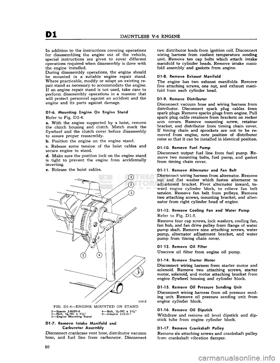
Dl-6.
Mounting Engine
On
Engine Stand
Refer
to Fig. Dl-4.
a.
With
the
engine
supported by a hoist, remove
the clutch housing and clutch. Match
mark
the flywheel and the clutch cover before disassembly to assure proper reassembly.
b. Position the
engine
on the
engine
stand.
c. Release
some
tension of the hoist cables and secure
engine
to stand.
d.
Make sure the position lock on the
engine
stand
is tight to prevent the
engine
from accidentally
inverting.
e.
Release the hoist cables.
FIG.
D1
-4—ENGINE
MOUNTED
ON
STAND
1—
Spacer
J-8690-6
A—Bolt,
i/2-NC
x 3i/2"
2—
Bolt,
3/a-NC
x 4*/2" 5—Adapter 21316-J 3—
Engine
Mounting Stand
Dl-7.
Remove Intake Manifold
and
Carburetor Assembly
Disconnect crankcase vent
hose,
distributor vacuum
hose,
and fuel line from carburetor. Disconnect two distributor leads from ignition coil. Disconnect
wiring
harness from coolant temperature sending
unit.
Remove ten cap
bolts
which attach intake
manifold to cylinder heads. Remove intake mani
fold assembly and gaskets from
engine.
Dl-8. Remove Exhaust Manifold
The
engine
has two exhaust manifolds. Remove five attaching screws, one nut, and exhaust mani
fold from each cylinder head.
Dl-9.
Remove Distributor
Disconnect vacuum
hose
and wiring harness from
distributor.
Disconnect spark plug cables from
spark
plugs. Remove sparks plugs from
engine.
Pull
spark
plug cable retainers from brackets on rocker
arm
covers. Remove mounting screw, retainer
bracket,
and distributor from timing chain cover.
If
timing chain and sprockets are not to be re
moved from
engine,
note
position of distributor
rotor so that it can be installed in identical position.
Dl-10. Remove
Fuel Pump
Disconnect output fuel line from fuel pump. Re
move
two mounting bolts, fuel pump, and gasket
from
timing chain cover.
Dl-11.
Remove Alternator
and Fan
Belt
Disconnect wiring harness from alternator. Remove nut and flat washer which fasten alternator to
adjustment bracket. Pivot alternator
inward,
to
ward
engine
cylinder block, to relieve fan belt
tension. Remove fan belt from pulleys. Remove
two attaching screws, mounting bracket, and alter nator from right cylinder head of
engine.
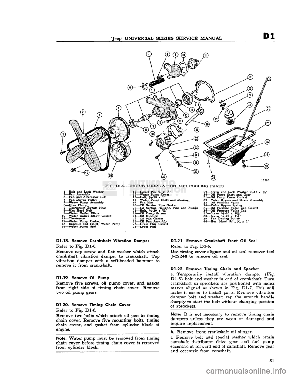
Dl-12.
Remove Cooling
Fan and
Water Pump
Refer
to Fig. Dl-5.
Remove four cap screws, lock washers, cooling fan,
fan
hub, and fan drive pulley from flange of water
pump shaft. Remove nine attaching screws, water
pump, alternator adjustment bracket, and water pump from timing chain cover.
Dl-13.
Remove
Oil
Filter
Unscrew
oil filter from
engine
oil pump.
Dl-14.
Remove Starter Motor
Disconnect wiring harness from starter motor and
solenoid. Remove two attaching screws, starter motor, solenoid, and motor attaching bracket from
engine
flywheel housing and cylinder block.
Dl-15.
Remove
Oil
Pressure Sending Unit
Disconnect wiring harness from oil pressure send
ing unit. Remove oil pressure sending unit from
engine
cylinder block.
Dl-16.
Remove
Oil
Dipstick
Withdraw
and remove oil level dipstick and dip
stick
tube
from
engine
cylinder block.
Dl-17.
Remove Crankshaft Pulley
Remove six attaching screws and crankshaft pulley
from
crankshaft vibration damper. 80
Page 81 of 376
'Jeep'
UNIVERSAL
SERIES
SERVICE
MANUAL
Dl
13296
FIG.
Dl-5—ENGINE
LUBRICATION
AND
COOLING
PARTS
1— Bolt and
Lock
Washer
2—
Fan
Assembly
3—
Fan
and Alternator Belt
4—
Fan
Driven Pulley 5— Water Pump Assembly
6—
Hose
Clamp 7— Thermostat Bypass
Hose
8—Hex
Head Bolt
9— Water Outlet Elbow
10— Water Outlet Elbow Gasket
11— Thermostat
12— Water Pump Gasket
13— Impeller and Insert, Water Pump
14— Water Pump Seal 15— Dowel Pin % x Vfc"
16— Water Pump Cover
17— Bolt,
1/4-20
x 1"
18— Water Pump Shaft and Bearing
19—
Fan
Hub
20—
-Oil
Suction Pipe Gasket
21—
Oil
Suction Housing, Pipe and Flange
22— Bolt,
y4-20
x s/8"
23—
Oil
Pump Screen
24—
Oil
Dipstick
25—
Oil
Pan Gasket
26—
Oil
Pan Assembly
27—
Drain
Plug Gasket
28—
Drain
Plug 29— Screw and
Lock
Washer #6-18 x %
30—
Oil
Pump Shaft and Gear
31—
Oil
Pump Cover Gasket
32— Valve Bypass and Cover Assembly
33—
Oil
Pressure Valve 34— Valve Bypass Spring
35—
Oil
Pressure Valve Cap Gasket
36—
Oil
Pressure Valve Cap
37— Screw V4-20 x lVg"
38— Screw 1/4-20 x 1W' 39—
Fan
Driving Pulley
40— Hex. Head Bolt, x 1"
Dl-13.
Remove
Crankshaft
Vibration Damper
Refer
to Fig. Dl-6.
Remove cap screw and flat washer which attach
crankshaft
vibration damper to crankshaft. Tap
vibration
damper with a soft-headed hammer to remove it from crankshaft.
Dl-19.
Remove Oil Pump
Remove five screws, oil pump cover, and gasket
from
right side of timing chain cover. Remove
two oil pump gears.
D1-20.
Remove Timing Chain Cover
Refer
to Fig. Dl-6. Remove two
bolts
which attach oil pan to timing
chain
cover. Remove five mounting bolts, timing
chain
cover, and gasket from cylinder block of
engine.
Note:
Water pump must be removed from timing
chain
cover before timing chain cover is removed
from
cylinder block.
Dl-21.
Remove Crankshaft Front
Oil
Seal
Refer
to Fig. Dl-6.
Use timing cover aligner and oil seal remover
tool
J-22248 to remove oil seal.
Dl-22.
Remove Timing Chain
and
Spocket
a.
Temporarily install vibration damper (Fig.
Dl-6)
bolt and washer in end of crankshaft.
Turn
crankshaft
so sprockets are positioned with index
marks
aligned as shown in Fig. Dl-7.
This
will
make it easier to install parts. Remove vibration
damper bolt and washer; rap the wrench handle
sharply
to start the bolt without changing position
of sprockets.
Note:
It is not necessary to remove timing chain
dampers unless they are worn or damaged and
require
replacement.
b. Remove front crankshaft oil slinger.
c. Remove bolt and special washer which retain
camshaft distributor drive gear and fuel pump
eccentric at forward end of camshaft. Remove gear
and
eccentric from camshaft. 81
Page 102 of 376
![JEEP CJ 1953 Service Manual
Dl
DAUNTLESS
V-6
ENGINE
FIG.
Dl-41—WATER
PUMP
AND
TIMING CHAIN COVER BOLT LOCATION
Cover
Bolts
alternately and evenly 8 to 12 lb-ft. [1,10 a 1,66
kg-m.].
Dl-88.
Install
Cranksh](/manual-img/16/57040/w960_57040-101.png "JEEP CJ 1953 Service Manual
Dl
DAUNTLESS
V-6
ENGINE
FIG.
Dl-41—WATER
PUMP
AND
TIMING CHAIN COVER BOLT LOCATION
Cover
Bolts
alternately and evenly 8 to 12 lb-ft. [1,10 a 1,66
kg-m.].
Dl-88.
Install
Cranksh")
Dl
DAUNTLESS
V-6
ENGINE
FIG.
Dl-41—WATER
PUMP
AND
TIMING CHAIN COVER BOLT LOCATION
Cover
Bolts
alternately and evenly 8 to 12 lb-ft. [1,10 a 1,66
kg-m.].
Dl-88.
Install
Crankshaft
Vibration
Damper
a.
Lubricate
the vibration damper hub
before
in
stallation to prevent
damage
to the crankshaft
front oil seal during installation and when the
engine
is first started.
b.
Install
the vibration damper on the crankshaft.
Secure it with its attaching flat washer and screw.
Torque
the screw to a minimum of 140 lb-ft.
[19,35
kg-m.].
Dl-89.
Install
Crankshaft Pulley
Secure the crankshaft pulley to the crankshaft
vibration
damper with six screws. Torque screws 18 to 25 lb-ft. [2,5 a 3,4 kg-m.].
Dl-90.
Install
Oil
Level
Dipstick
Insert
oil level dipstick
into
the dipstick tube.
Dl-91.
Install
Oil
Pressure Sending Unit
Install
oil pressure sending unit in cylinder block.
Connect electrical wiring harness to unit.
Dl-92.
Install Starting Motor
Secure starting motor and
solenoid
assembly to
the flywheel housing and cylinder block with two attaching screws. Torque screw, which attaches this
assembly to the flywheel housing, 30 to 40 lb-ft. [4,1 a 5,5 kg-m.]. Torque screw, which attaches
bracket
to cylinder block, 10 to 12 lb-ft. [1,4 a 1,7 kg-m.].
Dl-93.
Install
Oil
Filter
Install
a new oil filter
element
at oil filter nipple,
at
left
side
of timing chain cover. Torque 10 to 15 lb-ft. [1,38 a 2,07 kg-m.].
D1-94. Install Water Pump
Be
certain that mating surfaces of the water pump
and
timing chain cover are clean.
Install
a new
gasket
on the pump flange. Secure the pump and
alternator adjustment bracket to the cover with
nine attaching bolts. Torque
bolts
6 to 8 lb-ft. [0,83 a 1,10 kg-m.]. Refer to Fig. Dl-41.
D1-9S.
Install
Cooling Fan
Secure the cooling fan, fan hub, and fan drive
pulley to the water pump shaft
flange
with four
attaching screws. Torque screws 17 to 23 lb-ft. [2,35 a 3,18 kg-m.].
Dl-96.
Install
Alternator
and Fan
Belt
Mount the alternator and bracket assembly on
right
cylinder head with two attaching screws.
Torque
screws 30 to 40 lb-ft. [4,1 a 5,5 kg-m.].
Fasten
the alternator
loosely
to its adjustment
bracket
with attaching flat washer and nut.
Install
the fan
belt
on its pulleys. Pivot the alternator
outward,
away from cylinder block, to apply fan
belt
tension. Adjust fan
belt
tension to 80 lb. [36,2 kg.];
tighten
alternator-to-adjustment bracket
nut to secure adjustment
setting.
Connect wiring
harness to alternator.
Dl-97.
Install
Fuel Pump
Install
two mounting
bolts
and new
gasket
on
flange
of fuel pump. Secure pump to timing chain cover with screws; torque screws 17 to 23 lb-ft. [2,35 a 3,8 kg-m.]. Connect
output
fuel line to
pump.
Dl-98.
Install Exhaust Manifold
Secure each of two exhaust manifolds to corre
sponding cylinder head with five attaching screws,
and
one nut. Torque screws and nut 15 to 20 lb-ft. [2,07 a 2,8 kg-m.]. See Fig. Dl-42.
Dl-99.
Install Distributor
Insert
distributor drive gear
into
distributor mount-
FIG.
Dl-42—EXHAUST
MANIFOLD INSTALLATION
1—Torque
Bolts—15
to 20
lb-ft.
[2,07 a 2,8
kg-m.]
102
Page 104 of 376

Dl
DAUNTLESS
V-6
ENGINE
e.
Connect electrical wiring harness to coolant
temperature sending unit. Connect two distributor leads to ignition coil. Connect fuel line
between
fuel pump and carburetor, vacuum
hose
between
distributor and carburetor, and crankcase vent
hose
to intake manifold
below
rear
of carburetor.
FIG.
D1-46—-INTAKE
MANIFOLD
INSTALLATION
1—Long Bolt 2—Open Bolt Hole
Dl-102.
ENGINE INSTALLATION
Install
the
engine
in the vehicle in the following
procedure listed
below:
a.
Attach suitable sling to
engine
lifting
eyes
and,
using a hoist, lift the
engine
from blocks or
engine
stand.
b. When
engine
is free of the stand lower it slowly
into
the
engine
compartment of the vehicle.
Note:
The
engine
and transmission must be lined
up to
engage
the main shaft and clutch plate spline
while sliding the
engine
rearward
into
the mounting
position.
c.
Install
and tighten up
bolts
securing
engine
to
flywheel housing.
d.
Install
and tighten front
engine
mounting bolts.
e.
Remove sling from the
engine.
I.
Connect exhaust pipes to right and
left
engine
manifolds.
g. Connect choke cable support bracket to
car
buretor.
h.
Connect
engine
fuel
hoses
and fuel lines at right
frame
rail.
I.
Connect fuel lines.
j.
Mount
engine
starter motor assembly to
engine.
k.
Connect battery cable and wiring to
engine
starter
motor.
I.
Connect
engine
wiring harnesses to connectors
located on
engine
firewall.
Note:
On
engines
equipped with exhaust emission
control, replace the air pump, air distributor mani
fold, and anti-backfire (gulp) valve. See Section F2.
m. Replace radiator, and secure with bolts,
n.
Replace and tighten right and
left
radiator sup
port rods.
0. Connect upper and lower radiator
hoses
to the
engine.
p. Connect alternator wiring harness from connec
tor at regulator,
q.
Replace air cleaner.
r.
Connect battery ground cable from the battery
to the
engine
and the
engine
ground strap,
s.
Replace the hood.
After
the
engine
is installed in the vehicle,
fill
radiator
with coolant and
engine
with oil (Refer to
Lubrication
Section B), then perform an
engine
Tune-up
and road
test
(Refer to Tune-up Sec
tion C).
Dl-103.
FINAL IN-VEHICLE ADJUSTMENTS
a.
Clean
battery terminals and check battery.
b.
Check
ignition wires and connections.
c. Service carburetor air cleaner.
d.
Service positive crankcase ventilation valve.
e.
Check
fuel lines.
f. Gap and install new
spark
plugs.
g.
Check
distributor
points
and capacitor; replace
if
necessary.
h.
Check
ignition (distributor) timing; reset if
necessary. 1.
Check
carburetor adjustments; reset if necessary,
j.
With
engine
fully warmed up, tighten cylinder
head and manifold
bolts
and nuts to specified
torque.
Check
cylinder head
gaskets
and
bolts
for
air
or coolant leaks.
Note:
Tightness of cylinder head
bolts
should be
checked and corrected after 500 miles [800 km.]
of normal operation and again at 1000 miles [1600
km.].
k.
Check
fan belt tension; adjust if necessary.
I.
Check
for and correct any oil leak, fuel leak or
coolant leak. 104