1953 JEEP CJ Wheel bearing
[x] Cancel search: Wheel bearingPage 321 of 376
'Jeep'
UNIVERSAL
SERIES SERVICE
MANUAL
O
column assembly down through the floor pan open
ing and out from under vehicle.
0-24.
Disassembly
of
Steering
Gear
Refer
to Fig. 0-2.
When
the steering gear arm is installed on early
production vehicles, the line across the face of the
arm
and the end of the shaft should be in align ment. On later production vehicles, blind splines
on the lever shaft and in the steering gear arm en
sure
correct positioning of the arm.
a.
Remove the steering gear arm with a puller
C-3646.
Caution:
Do not use a hammer or
wedge
to re
move
the steering arm from the shaft and lever.
This
can cause damage to the shaft assembly.
b.
Loosen the lock nut and unscrew the adjusting
screw
two turns.
c.
Remove the side cover screws and washers. Re
move
the side cover and gasket.
d.
Remove lever shaft.
e.
Remove upper cover plate screws. Remove cam,
wheel tube, and bearing assembly from the housing.
f.
Clean
all parts with suitable cleaning solvent and wipe dry.
g.
After dismantling as outlined above is com
pleted, inspect cam
grooves
for wear, chipping and
scoring,
also the
ball
races on the cam ends and the
separate
ball
cups. Existence of any of
these
condi tions indicates the necessity for parts replacement.
h.
Inspect the tapered stud mounted on the lever
shaft for flat
spots
and chipping. In the case of
either, replacement is usually advisable. Inspect the
lever shaft for wear and
test
the fit of the shaft in
the bushings.
i.
Inspect condition of the oil seal at outer end of
lever shaft and the bearing at top end of steering
column.
0-25.
Reassembly
of
Steering
Gear
e Refer to Fig. 0-2.
Reassemble all parts to wheel tube in reverse order
of dismantling. Assemble cam, wheel tube and
bearing
assembly in housing, seating the lower
bearing
ball
cup in the housing.
Note:
New plastic retainer type cam bearings are
now available for the Ross steering gears. The new
bearings replace, and are interchangeable with,
the lock ring type cam bearings on gears equipped
with
early type cams.
With
adjusting shims in place, assemble upper
cover and adjust the cam bearings.
Assemble lever shaft in housing and with gasket
in
place assemble the side cover and set adjusting
screw
for a minimum backlash of the studs in the
cam
groove, with the steering gear at the center
point of travel.
When
assembling upper bearing spring and spring
seat in jacket tube make sure that the spring seat
is positioned correctly. It must be installed with
the lengthwise flange down against the bearing and
not up inside of spring coil.
0-26.
Installation
of
Steering
Gear
a.
After the gear has been properly adjusted, as
outlined in Par. 0-5, install steering gear assembly
in
chassis in the reverse order in which it was re
moved.
b.
After installing the assembly in the vehicle,
jack
up front of vehicle and place the front wheels
in
the straight ahead position.
c.
Temporarily install the steering wheel to locate
the mid-position of the steering gear. To locate the mid-position,
turn
the steering wheel as far to the
right
as possible and then
turn
in the
opposite
di
rection
as far as possible, noting the total number
of turns.
Turn
the wheel back just ^ of the total movement to place the gear in mid-position.
d.
With
the steering gear in mid-position and the
wheels in the straight ahead position install steer ing gear arm on lever shaft with the
ball
end down.
When
installed the line across the face of the arm
and
end of shaft should be in alignment.
0-27.
Steering
Wheel
Installation
•
Refer to Fig. 0-2.
a.
Install
steering wheel and spring on shaft.
Align
scribe marks on shaft and hub of wheel.
b.
Install
steering shaft nut and torque 20 to 25
lb-ft. [2,8 a 3,4 kg-m.].
c.
Install
horn cap. Test horn.
321
Page 322 of 376
o
STEERING
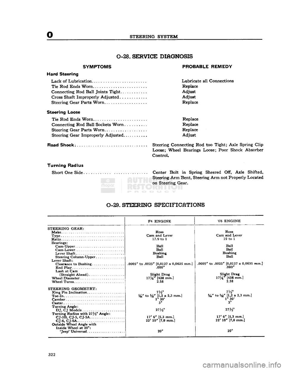
SYSTEM 0-28.
SBKF1CE
DIAGNOSIS
SYMPTOMS PROBABLE REMEDY
Hard Steering
Lack
of Lubrication Lubricate all Connections
Tie
Rod
Ends
Worn.
Replace
Connecting Rod
Ball
Joints
Tight. Adjust
Cross
Shaft Improperly Adjusted Adjust Steering
Gear
Parts
Worn...................
Replace
Steering
Loose
Tie
Rod
Ends
Worn
Replace
Connecting Rod
Ball
Sockets
Worn
Replace
Steering
Gear
Parts
Worn.
Replace
Steering
Gear
Improperly Adjusted.
......
Adjust
Road Shook; Steering Connecting Rod too Tight;
Axle
Spring
Clip
Loose; Wheel Bearings Loose;
Poor
Shock Absorber
Control,
Turning Radius
Short One
Side
Center
Bolt
in Spring
Sheered
Off,
Axle
Shifted, Steering Arm Bent, Steering Arm not Properly Located
on
Steering
Gear.
0-29.
STEERING
SPECIFICATIONS
F4
ENGINE
V6
ENGINE
STEERING
GEAR:
Make.
Ross
Ross
Type
Cam
and Lever
Cam
and Lever
Ratio..
17.9 to 1
19 to 1
Bearings:
Ball
Cam-Upper
Ball Ball
Cam-Lower
Ball Ball
Lever
Shaft Bushing
Bushing
Steering Column-Upper
Ball
Ball
Lever
Shaft:
.0005*
to
.0025"
[0,0127
a
0,0635
mm.]
Clearance
to Bushing
.0005"
to
.0025"
[0,0127
a
0,0635
mm.j
.0005*
to
.0025"
[0,0127
a
0,0635
mm.]
End
Play .000'
.000"
Lash
at Cam (Straight Ahead) Slight Drag
Slight Drag
Wheel Diameter.
17M*
(438 mm.]
17M*
[438 mm.]
Wheel
Turns.
2.58
2.58
STEERING
GEOMETRY:
King
Pin Inclination
m°
I
72
Toe-In.
W to W U,2 a 2,3 mm.] W to W [1,2 a 2,3 mm.]
Camber
1°
30'
1°
30'
Caster
3°
3°
Turning
Angle:
27K°
DJ,
CJ Models
27K° 273^°
Turning
Radius with 27^° Angle: 17' 6" [5,3 mm.]
CJ-3B,
CJ-5, CJ-5A.
17' 6" [5,3 mm.]
17' 6" [5,3 mm.]
CJ-6,
CJ-6A
22' 10" [7,0 mm.]
22' 10" [7,0 mm.]
Outside Wheel Angle with Inside Wheel at 20°:
20° 20°
322
Page 325 of 376
'Jeep'
UNIVERSAL
SERIES SERVICE
MANUAL
P The
standard parking brakes (Fig. P-3) consist of
cable-controlled linkage for applying the rear wheel
brake
shoes
mechanically. A single cable from the
parking
brake control lever is connected, by means of an equalizer, to cables leading to individual rear
brakes.
A lever attached to the secondary
shoe,
with a link acting against the
primary
shoe,
expands the
shoes
into
contact with the drums.
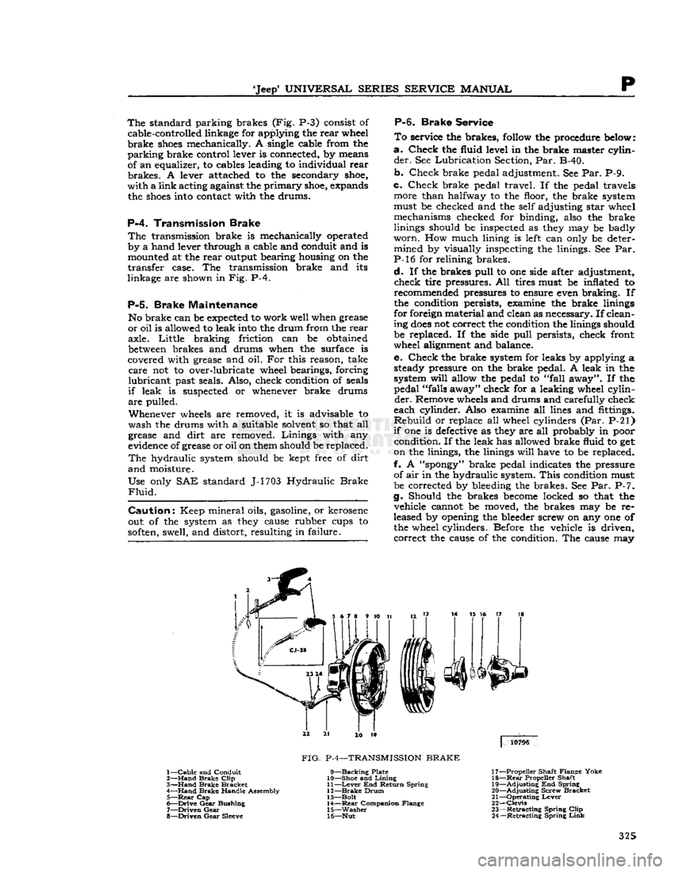
P-4.
Transmission Brake
The
transmission brake is mechanically operated
by a hand lever through a cable and conduit and is mounted at the rear output bearing housing on the
transfer case. The transmission brake and its
linkage are shown in Fig. P-4.
P-5.
Brake Maintenance
No brake can be
expected
to work well when grease
or oil is allowed to leak
into
the drum from the rear axle. Little braking friction can be obtained
between
brakes and drums when the surface is
covered with grease and oil. For this reason, take
care
not to over-lubricate wheel bearings, forcing
lubricant
past seals. Also, check condition of seals
if
leak is suspected or whenever brake drums
are
pulled.
Whenever
wheels
are removed, it is advisable to
wash the drums with a suitable solvent so that all
grease and dirt are removed. Linings with any
evidence of grease or oil on them should be replaced.
The
hydraulic system should be kept free of dirt
and
moisture.
Use only SAE standard J-1703 Hydraulic
Brake
Fluid.
Caution:
Keep mineral oils, gasoline, or kerosene
out of the system as
they
cause rubber cups to
soften,
swell, and distort, resulting in failure.
P-6.
Brake
Service
To
service the brakes,
follow
the procedure
below:
a.
Check the fluid level in the brake master cylin
der.
See Lubrication Section, Par. B-40.
b. Check brake pedal adjustment. See Par. P-9.
c. Check brake pedal travel. If the pedal travels more than halfway to the floor, the brake system
must be checked and the self adjusting star wheel mechanisms checked for binding, also the brake
linings should be inspected as
they
may be badly
worn.
How much lining is
left
can only be deter mined by visually inspecting the linings. See Par.
P-l6 for relining brakes.
d.
If the brakes pull to one side after adjustment, check tire pressures. All tires must be inflated to recommended pressures to ensure even braking. If
the condition persists, examine the brake linings
for foreign material and clean as necessary. If clean
ing
does
not correct the condition the linings should be replaced. If the side pull persists, check front
wheel alignment and balance.
e. Check the brake system for leaks by applying a steady pressure on the brake pedal. A leak in the
system
will
allow the pedal to "fall away". If the pedal "falls away" check for a leaking wheel cylin
der.
Remove
wheels
and drums and carefully check
each cylinder. Also examine all lines and fittings.
Rebuild
or replace all wheel cylinders (Par. P-21)
if
one is
defective
as
they
are all probably in poor condition. If the leak has allowed brake fluid to get
on the linings, the linings
will
have to be replaced.
f. A
"spongy"
brake pedal indicates the pressure of air in the hydraulic system.
This
condition must
be corrected by bleeding the brakes. See Par. P-7.
g. Should the brakes
become
locked so that the vehicle cannot be moved, the brakes may be re
leased by opening the bleeder screw on any one of the wheel cylinders. Before the vehicle is driven, correct the cause of the condition. The cause may
3
14 15 16 17 18
4
10796
1—
Cable
and Conduit
2—
Hand
Brake
Clip
3—
Hand
Brake
Bracket
4—
Hand
Brake
Handle Assembly 5—
Rear
Cap
6—
Drive
Gear
Bushing
7—
Driven
Gear
8—
Driven
Gear
Sleeve
FIG.
P-4—TRANSMISSION
BRAKE
9—Backing
Plate
10— Shoe and
Lining
11—
Lever
End Return Spring
12—
Brake
Drum
13— Bolt 14—
Rear
Companion Flange
15—
Washer
16— Nut 17— Propeller Shaft Flange Yoke
18—
Rear
Propeller Shaft
19—
Adjusting
End Spring
20—
Adjusting
Screw Bracket
21—
Operating
Lever
22—
Clevis
23—
Retracting
Spring
Clip
24—
Retracting
Spring
Link
325
Page 330 of 376
p
BRAKES
c. To assemble the brake unit, place the
shoes
on
the backing plates and secure with the
shoe
hold
down pin and clip. Place the adjusting lever on the
secondary
shoe
web making sure the
slot
in the lever
engages
to full depth with the
slot
in the
shoe
web. The adjuster levers are painted RED for right hand brakes and
BLUE
for
left
hand brakes.
d.
Install the adjusting screw assemblies. The star
wheel must be installed over the adjusting
hole
in the backing plate.
Notes
Interchanging adjusting screw assemblies
will
cause
shoe
to retract rather than expand.
e. Assemble the lower spring that
fastens
to the
two
shoe
webs.
THE LONG HOOK
END should
be secured in the small
hole
in the secondary
shoe
and
should be
UNDER
the
shoe
web. The short hook end should be secured in the small
hole
in the
primary
shoe.
If the spring is installed correctly,
the long hook end
will
not interfere with either the lever or the star wheel
teeth.
f. Install the anchor block with arrow pointing in the forward direction of the drum rotation. Place the
guide
plate over the anchor pin and using Tool
C-3
785 install the
shoe
return springs (secondary
spring
first) with the long hook end flat against the
guide
plate.
g. Install the lever crank in the small
hole
on the secondary
shoe
web, the
left
lever crank on the left,
and
right lever crank on the right. A
"L"
or
"R"
is
located on the
hexagon
side of the crank for identi
fication.
Make
certain the lever rotates freely on
the
hexagon
head screw.
fi.
Assemble the short wire link with large hook by
first
inserting the "S" shape
offset
end
into
the
lever crank
hole
which is
closest
to the
hexagon
head and then snap the hook end of the link in the top
groove
of the anchor pin.
i.
Insert the long link with "S" shaped end in the
crank
lever.
Lift
the adjuster lever up
enough
to hook the link in the
slot
of the adjusting lever. The
adjusting lever
will
then
engage
the star wheel
teeth
between
M%
[1,59 mm.]
above
or
below
the centerline of adjusting screw assembly,
j.
Lubricate the wheel bearings and install the
brake
drum and adjust the wheel bearing to the proper preload.
k. Adjust the brakes as described in Par. P-19.
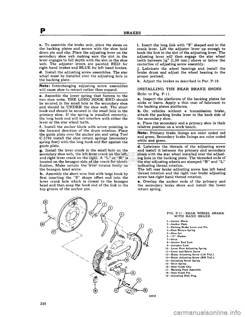
INSTALLING
THE
REAR BRAKE SHOES
Refer
to Fig. P-ll.
a.
Inspect the platforms of the backing plates for
nicks
or
burrs.
Apply a thin coat of lubricant to
the backing plates platforms.
b. On vehicles without a transmission brake,
attach the parking brake lever to the back side of
the secondary
shoe.
c. Place the secondary and a primary
shoe
in their relative position on a work bench.
Note:
Primary
brake linings are color coded red
and
green. Secondary brake linings are color coded
white and green.
d.
Lubricate the threads of the adjusting screw
and
install it
between
the primary and secondary
shoes
with the star wheel installed over the adjusting
hole
in the backing plate. The threaded
ends
of
the star adjusting
wheels
are stamped
"R"
and
"L"
indicating thread rotation.
The
left
rear brake adjusting screw has
left
hand
thread rotation and the right rear brake adjusting screw has right hand thread rotation.
e. Overlap the anchor
ends
of the primary and the secondary brake
shoes
and install the lower
return
spring.
Page 334 of 376
p
BRAKES
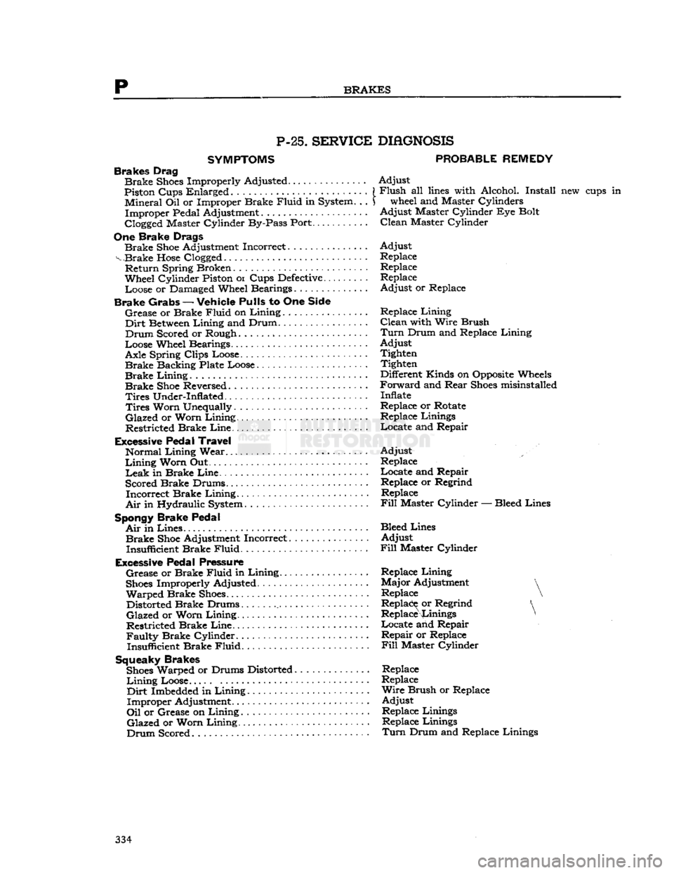
P-25.
SERVICE
SYMPTOMS
Brakes Drag
Brake
Shoes
Improperly Adjusted
Piston Cups Enlarged . . •.
«•
Mineral
Oil or Improper Brake
Fluid
in System. . .
Improper
Pedal Adjustment
Clogged Master Cylinder By-Pass Port...
One
Brake Drags
Brake
Shoe
Adjustment Incorrect
v Brake
Hose
Clogged.
Return
Spring Broken
Wheel Cylinder Piston
01
Cups
Defective.........
Loose or Damaged Wheel Bearings
Brake Grabs
—
Vehicle Pulls
to One
Side
Grease
or Brake
Fluid
on
Lining................
Dirt
Between
Lining
and Drum
Drum
Scored or Rough
Loose Wheel Bearings. .
Axle Spring Clips Loose
Brake
Backing Plate Loose
Brake
Lining
..
Brake
Shoe
Reversed
Tires
Under-Inflated -
Tires
Worn Unequally
Glazed
or Worn
Lining
Restricted Brake
Line
Excessive Pedal Travel
Normal
Lining
Wear
Lining
Worn Out ... .
Leak
in Brake
Line.
Scored Brake Drums
Incorrect
Brake
Lining.
Air
in Hydraulic System
Spongy Brake Pedal
Air
in
Lines.
Brake
Shoe
Adjustment Incorrect
Insufficient Brake
Fluid
Excessive Pedal Pressure
Grease
or Brake
Fluid
in
Lining
Shoes
Improperly Adjusted
Warped
Brake
Shoes
Distorted Brake Drums
Glazed
or Worn
Lining
Restricted Brake
Line
Faulty
Brake Cylinder Insufficient Brake
Fluid.
Squeaky Brakes
Shoes
Warped or Drums Distorted
Lining
Loose.....
Dirt
Imbedded in
Lining
Improper
Adjustment.
Oil
or Grease on
Lining
Glazed
or Worn
Lining.
Drum
Scored
DIAGNOSIS
PROBABLE
REMEDY
Adjust
Flush
all
lines
with Alcohol. Install new cups in wheel and Master Cylinders
Adjust
Master Cylinder Eye Bolt
Clean
Master Cylinder
Adjust
Replace Replace
Replace
Adjust
or Replace
Replace
Lining
Clean
with Wire Brush
Turn
Drum and Replace
Lining
Adjust
Tighten Tighten
Different Kinds on Opposite Wheels
Forward
and
Rear
Shoes
misinstalled
Inflate
Replace or Rotate Replace Linings
Locate
and Repair
Adjust
Replace
Locate
and Repair Replace or Regrind Replace
Fill
Master
Cylinder
— Bleed Lines
Bleed Lines
Adjust
Fill
Master Cylinder
Replace
Lining
Major
Adjustment
Replace
Replace or Regrind Replace Linings * .
Locate
and Repair
Repair
or Replace
Fill
Master Cylinder Replace
Replace
Wire
Brush or Replace
Adjust
Replace Linings Replace Linings
Turn
Drum and Replace Linings 334
Page 335 of 376
'Jeep'
UNIVERSAL
SERIES SERVICE
MANUAL
WHEELS
Contents
SUBJECT PAR.
GENERAL
Q-l Wheel Balancing. Q-2
WHEEL BEARING SERVICE.
......
Q-3
Checking
Front Wheel Bearings Q-4
Checking
Rear Wheel Bearings.
.......
.
Q-7
Front
Wheel Bearing Adjustment. Q-5
Rear
Wheel Bearing Adjustment — Flanged Axle Q-6
Rear
Wheel Bearing Adjustment —
Tapered
Axle Q-8 SUBJECT PAR.
REAR WHEEL
MOUNTING
.Q-9
BRAKE
DRUM
SERVICE.
......
. . .Q-10
TIRE
SERVICE.
.................
.Q-ll
Tire
Care
Q-l2
Tire
Removal and Installation. Q-l3
SPECIFICATIONS
. .Q-14
Q-l.
GENERAL
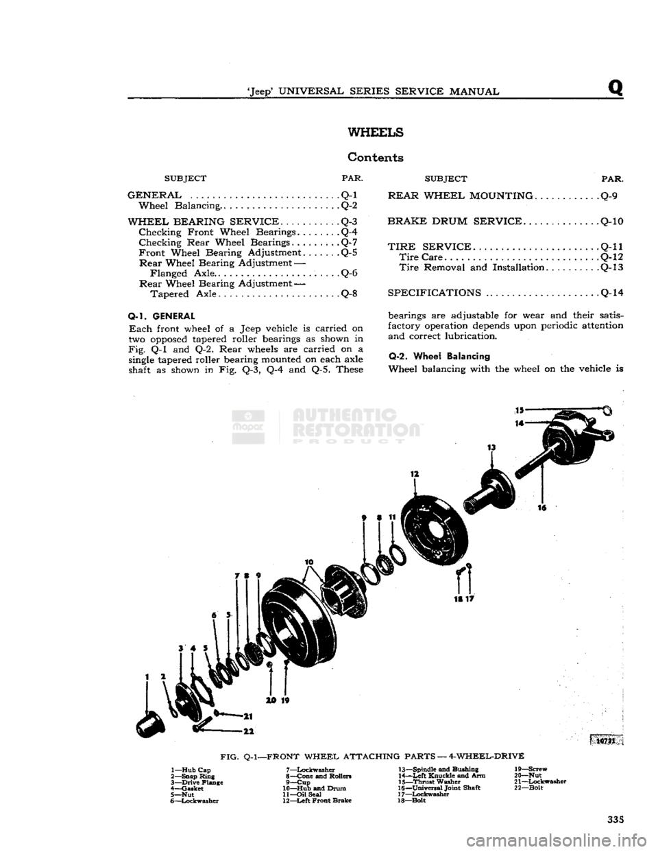
Each
front wheel of a Jeep vehicle is carried on
two
opposed
tapered roller bearings as shown in
Fig.
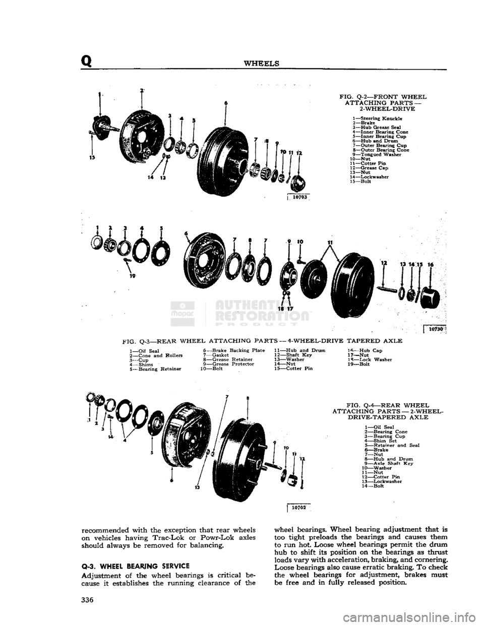
Q-l and Q-2. Rear
wheels
are carried on a
single
tapered roller bearing
mounted
on each axle
shaft as shown in Fig. Q-3, Q-4 and Q-5. These bearings are adjustable for wear and their satis
factory operation
depends
upon periodic
attention
and correct lubrication.
Q-2.
Wheel Balancing
Wheel balancing with the wheel on the vehicle is 18 17
10731
FIG.
Q-l—FRONT
WHEEL ATTACHING PARTS — 4-WHEEL-DRIVE 1— Hub Cap
2— Snap Ring
3—
Drive
Flange
4— Gasket 5— Nut
6—
Lockwasher
7—
Lockwasher
8— Cone and Rollers 9—
Cup
10— Hub and Drum 11—
Oil
Seal
12—
Left
Front Brake 13— Spindle and Bushing
14—
Left
Knuckle and Arm
15—
Thrust
Washer
16—
Universal
Joint Shaft
17—
Lockwasher
18—Bolt 19— Screw
20— Nut
21—
Lockwasher
22— Bolt 335
Page 336 of 376
Q
WHEELS
FIG.
Q-2—FRONT
WHEEL
ATTACHING
PARTS —
2-WHEEL-DRIVE
1—
Steering
Knuckle
2—
Brake
3— Hub
Grease
Seal
4—
Inner
Bearing
Cone
5—
Inner
Bearing
Cup
6—
Hub
and
Drum
7—
Outer
Bearing
Cup
8—
Outer
Bearing
Cone
9—
Tongued
Washer
10— Nut
11—
Cotter
Pin
12—
Grease
Cap
13— Nut
14—
Lockwasher
15—
Bolt
j
10703
is ir 10730
FIG.
Q-3—REAR
WHEEL
ATTACHING PARTS —
4-WHEEL-DRIVE
TAPERED
AXLE
1—
Oil
Seal
2—
Cone
and
Rollers
3— Cup
4—
Shims
5—
Bearing
Retainer
6—
Brake
Backing
Plate
7—
Gasket
8—
Grease
Retainer
9—
Grease
Protector
10—Bolt
11— Hub
and
Drum
12—
Shaft
Key
13—
Washer
14—
Nut
15—
Cotter
Pin
Ifi—Hub
Cap
17—Nut
18—
Ixick
Washer
19—Bolt
FIG.
Q-4—REAR
WHEEL
ATTACHING
PARTS —
2-WHEEL-
DRIVE-TAPERED
AXLE
1—
Oil
Seal
2—
Bearing
Cone
3—
Bearing
Cup
4—
Shim
Set
5—
Retainer
and
Seal
6—
Brake
7—
Nut
8—
Hub
and
Drum
9—
Axle
Shaft Key
10—
Washer
11— Nut
12—
Cotter
Pin
13—
Lockwasher
14—
Bolt
recommended with the exception that
rear
wheels
on vehicles having
Trac-Lok
or
Powr-Lok
axles
should always be removed for balancing.
Q-3. WHEEL
BEARING
SERVICE
Adjustment
of the wheel bearings is
critical
be cause it establishes the running clearance of the wheel bearings. Wheel bearing adjustment that is
too
tight
preloads the bearings and causes them
to run hot. Loose wheel bearings permit the drum hub to shift its position on the bearings as thrust loads
vary
with acceleration,
braking,
and cornering.
Loose
bearings also cause
erratic
braking.
To check
the wheel bearings for adjustment, brakes must
be free and in fully released position. 336
Page 337 of 376
'Jeep'
UNIVERSAL
SERIES SERVICE
MANUAL
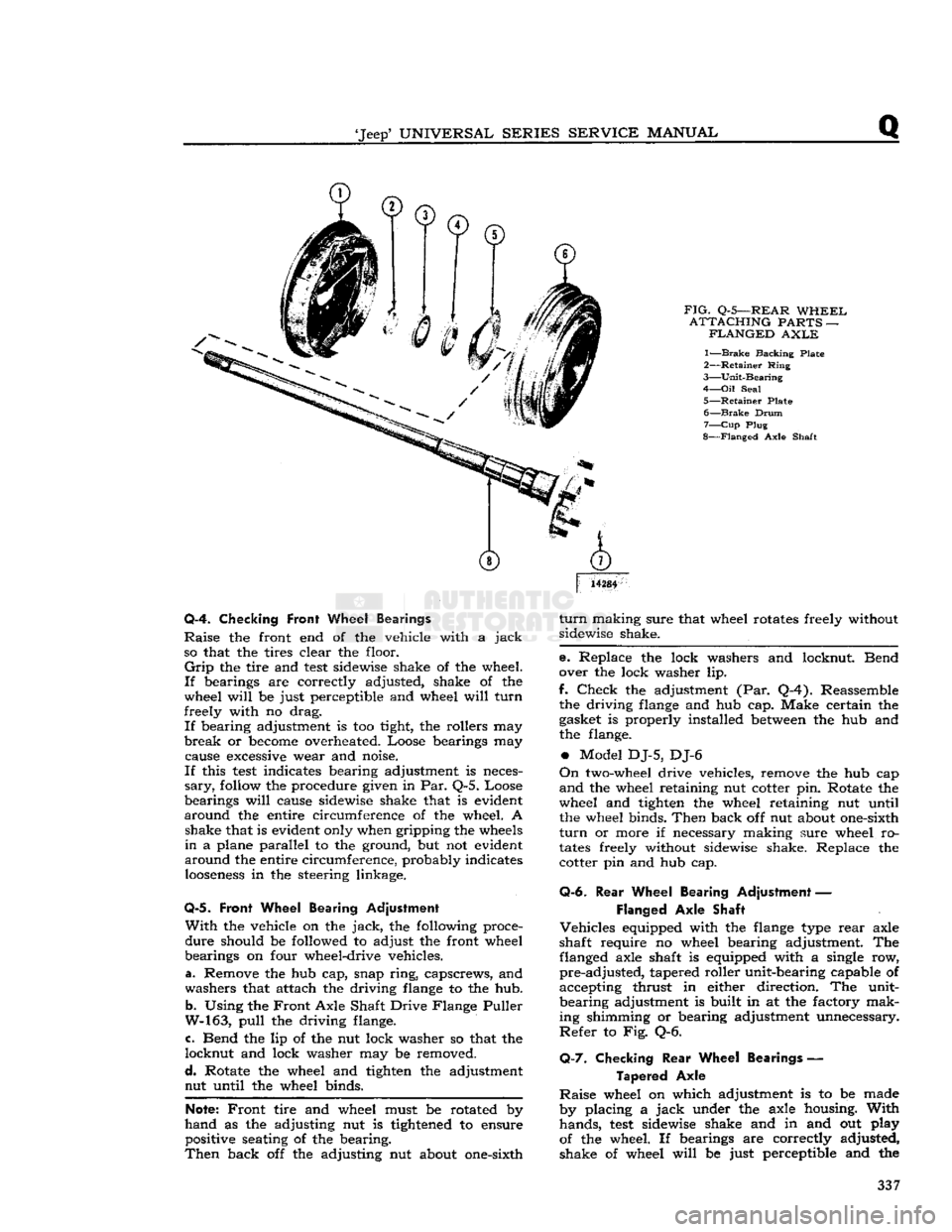
FIG.
Q-5—REAR
WHEEL
ATTACHING
PARTS —
FLANGED
AXLE
1—
Brake
Backing Plate
2—
Retainer
Ring
3—
Unit-Bearing
4—
Oil
Seal
5—
Retainer
Plate 6—
Brake
Drum
7—
Cup
Plug
8—
Flanged
Axle Shaft
14284
Q-4. Checking
Front
Wheel Bearings
Raise
the front end of the vehicle with a
jack
so that the tires clear the floor.
Grip
the tire and
test
sidewise shake of the wheel.
If
bearings are correctly adjusted, shake of the
wheel
will
be just perceptible and wheel
will
turn
freely with no drag.
If
bearing adjustment is too tight, the rollers may
break
or
become
overheated. Loose bearings may cause
excessive
wear and noise.
If
this
test
indicates bearing adjustment is neces
sary,
follow
the procedure given in Par. Q-5. Loose
bearings
will
cause sidewise shake that is evident
around
the entire circumference of the wheel. A shake that is evident only when gripping the
wheels
in
a plane parallel to the ground, but not evident
around
the entire circumference, probably indicates
looseness
in the steering linkage.
Q-5.
Front Wheel Bearing Adjustment
With
the vehicle on the
jack,
the following proce
dure
should be followed to adjust the front wheel
bearings on four wheel-drive vehicles.
a. Remove the hub cap, snap
ring,
capscrews, and
washers that attach the driving
flange
to the hub.
b.
Using the
Front
Axle Shaft Drive Flange Puller
W-163,
pull
the driving flange.
c. Bend the lip of the nut lock washer so that the
locknut
and lock washer may be removed.
d.
Rotate the wheel and tighten the adjustment nut until the wheel binds.
Note:
Front
tire and wheel must be rotated by
hand
as the adjusting nut is
tightened
to ensure positive seating of the bearing.
Then
back off the adjusting nut about one-sixth
turn
making sure that wheel rotates freely without
sidewise shake.
e. Replace the lock washers and locknut. Bend
over the lock washer lip.
f.
Check
the adjustment (Par. Q-4). Reassemble the driving
flange
and hub cap. Make certain the
gasket is properly installed
between
the hub and
the flange.
•
Model DJ-5, DJ-6
On
two-wheel drive vehicles, remove the hub cap
and
the wheel retaining nut cotter pin. Rotate the
wheel and tighten the wheel retaining nut until the wheel binds.
Then
back off nut about one-sixth
turn
or more if necessary making sure wheel ro
tates
freely without sidewise shake. Replace the cotter pin and hub cap.
Q-6.
Rear
Wheel Bearing Adjustment —
Flanged
Axle Shaft
Vehicles
equipped with the
flange
type
rear
axle
shaft require no wheel bearing adjustment. The flanged axle shaft is equipped with a single row,
pre-adjusted,
tapered roller unit-bearing capable of
accepting thrust in either direction. The unit-
bearing
adjustment is built in at the factory mak
ing shimming or bearing adjustment unnecessary.
Refer
to Fig. Q-6.
Q-7.
Checking
Rear
Wheel Bearings —
Tapered
Axle
Raise
wheel on which adjustment is to be made
by placing a
jack
under the axle housing.
With
hands,
test
sidewise shake and in and out play
of the wheel. If bearings are correctly adjusted,
shake of wheel
will
be just perceptible and the 337