1900 MITSUBISHI DIAMANTE check engine
[x] Cancel search: check enginePage 101 of 408
l
3-40 ENGINEANDENGINEOVERHAUL
Counterbaiance
19235861
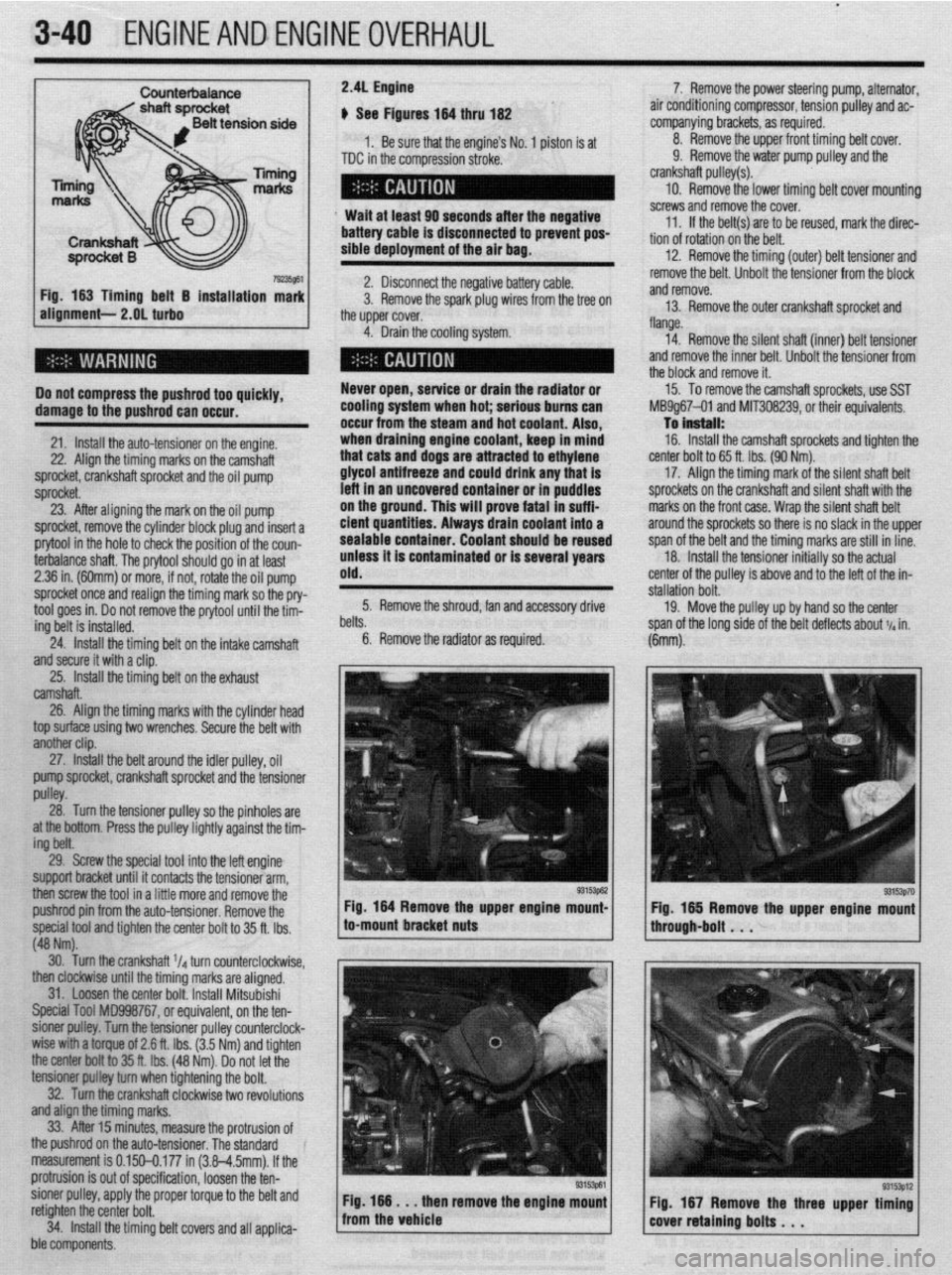
Fig. 163 Timing belt 5 installation mark
alignment- 2.OL turbo
Do not compress the pushrod too quickly,
damage to the pushrod can occur.
21. Install the auto-tensioner on the engine.
22. Align the timing marks on the camshaft
sprocket, crankshaft sprocket and the oil pump
sprocket.
23. After aligning the mark on the oil pump
: sprocket, remove the cylinder block plug and insert a
prytool in the hole to check the position of the coun-
terbalance shaft. The orvtool should ao in at least 7. Remove the power steering pump, alternator
air conditioning compressor, tension pulley and ac-
companying brackets, as required.
8 Remove the upper front timing belt cover.
9. Remove the water pump pulley and the
crankshaft pulley(s).
10. Remove the lower timing belt cover mountinf
screws and remove the cover.
11. If the belt(s) are to be reused, mark the direc.
tion of rotation on the belt.
12. Remove the timing (outer) belt tensioner and
remove the belt. Unbolt the tensioner from the block
and remove.
13. Remove the outer crankshaft sprocket and
flange.
14. Remove the silent shaft (inner) belt tensioner
and remove the inner belt. Unbolt the tensioner from
the block and remove it.
15. To remove the camshaft sprockets, use SST
Ml39g67-01 and MlT308239, or their equivalents.
To in!3tall:
16. Install the camshaft sprockets and tighten thr
center bolt to 65 ft. Ibs. (90 Nm).
17. Align the timing mark of the silent shaft belt
sprockets on the crankshaft and silent shaft with the
marks on the front case. Wrap the silent shaft belt
around the sprockets so there is no slack in the uppe
!
I span of the belt and the timing marks are still in line.
18. Install the tensioner initially so the actual
:enter of the pulley is above and to the left of the in-
jtallation bolt. 2.36 in. (60mm) or more, if not, rotai;! the oil pump
sprocket once and realign the timing mark so the pry-
24. Install the timing belt on the intake camshaft
and secure it with a clip. .
25. Install the timina belt on the exhaust old. 2.41 Engine
I: # See Figures 164 thru 162
1. Be sure that the engine’s No. 1 piston is at
TDC in the compression stroke.
Wait at least 90 seconds after the negative
battery cable is disconnected to prevent pos-
sible deployment of the air bag.
2. Disconnect the negative battery cable.
3. Remove the spark plug wires from the tree on
the upper cover.
4. Drain the cooling system.
Never open, service or drain the radiator or
cooling system when hot; serious bums can
occur from the steam and hot coolant. Also,
when draining engine coolant, keep in mind
that cats and dogs are attracted to ethylene
glycol antifreeze and could drink any that is
left in an uncovered container or in puddles
on the ground. This will prove fatal in suffi-
cient quantities. Always dram coolant into a
sealable container. Coolant should be reused
unless it is contaminated or is several years
tool goes in. Do not remove the on/ool until the tfrn- 5. Remove the shroud, fan and accessory drive
ing belt is installed. lelts.
6. Remove the radiator as required. 19. Move the pulley up by hand so the center
jpan of the lona side of the belt deflects about 11~ in.
camshaft.
26. Align the timing marks with the cylinder head
top surface using two wrenches. Secure the belt with
another clip.
27. tnstatf the belt around the idler pulley, oil
pump sprocket, crankshaft sprocket and the tensioner
pulley.
28. Turn the tensioner pulley so the pinholes are
at the bottom. Press the pulley lightly against the tim-
ing belt.
29. Screw the special tool into the left engine
support bracket until it contacts the tensioner arm,
then screw the tool in a little more and remove the
pushrod pin from the auto-tensioner. Remove the
special tool and tighten the center bolt to 35 ft. Ibs.
(48 Nm). Fig 164 Remove the upper engine mount-
to-mount bracket nuts al%@]
Pm3p70 Fig. 165 Remove the upper engine mount
through-bolt . . .
30. Turn the crankshaft ‘Id turn counterclockwise,
then clockwise until the timing marks are aligned.
31. Loosen the center bolt. Install Mitsubishi
Special Tool MD998767, or equivalent, on the ten-
sioner p&y. Turn the tensioner pulley counterclock-
wise with a torque of 2.6 ft. Ibs. (3.5 Nm) and tighten
the center boftto 35 ft. tbs. (48 Nm). Do not let the
tensioner pUtFey turn when tightening the bolt.
32. Turn the crankshaft clockwise two revolutions
and align the timing marks.
33. After 15 minutes, measure the protrusion of
the pushrod on the auto-tensioner. The standard
measurement is 0.150-0.177 in (3.8-4.5mm). If the
I protrusion is out of specification, loosen the ten-
I sioner pulley, apply the proper torque to the belt and
: retighten the center bolt.
34. Install the timing belt covers and all applica-
i ble components.
Page 103 of 408
.
3-42 ENGINEANDENGINEOVERHAUL
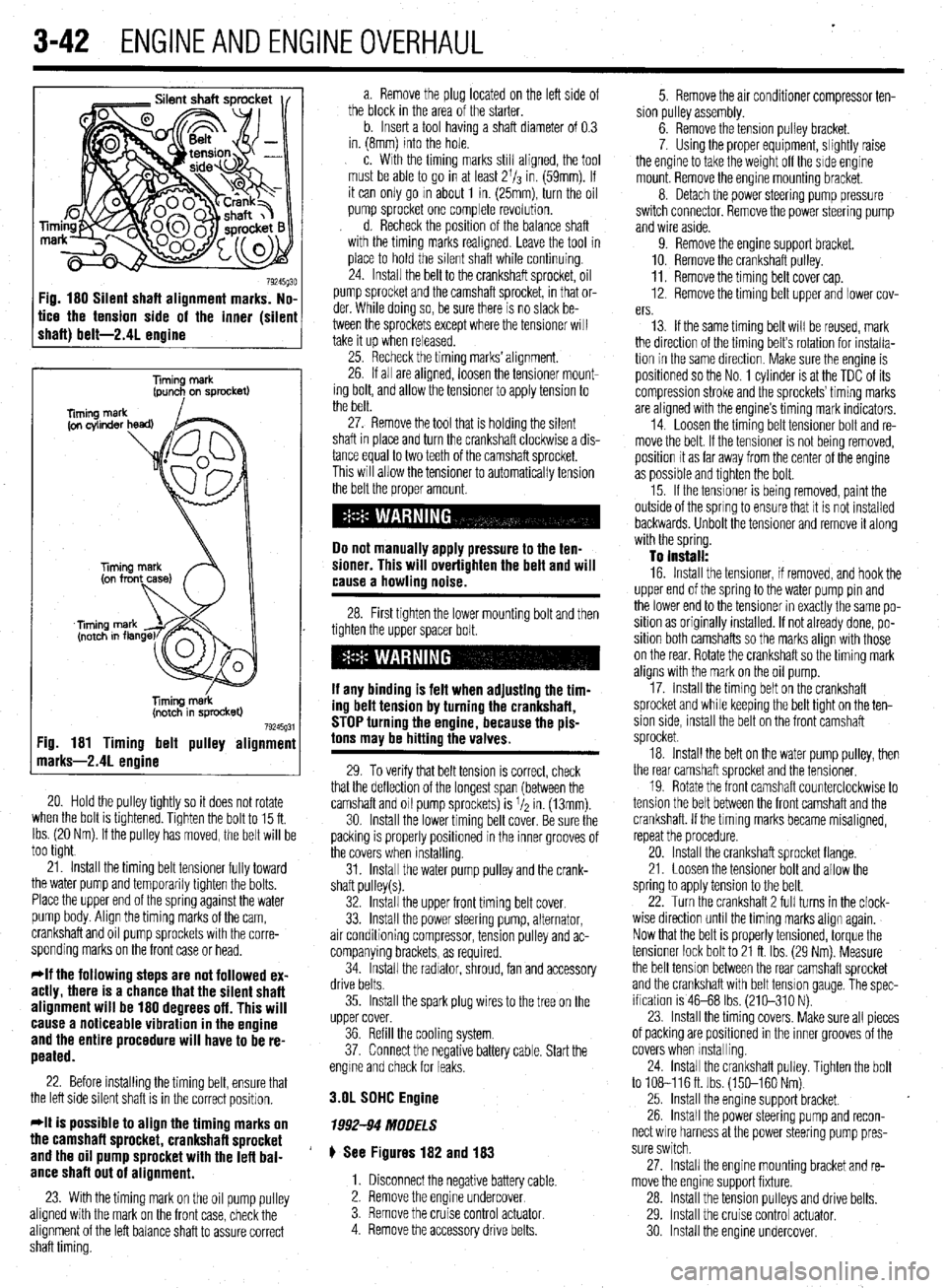
Fig. 180 Silent shaft alignment marks. No,
tice the tension side of the inner (silen
shaft) belt-2.41 enaine
Timing merk
(pun+ on sprocket)
liming m&k
(notch in sprocket)
79245g31 :ig. 181 Timing belt pulley alignmenl
narks-2.41 enoine
20. Hold the pulley tightly so it does not rotate
when the bolt is tlghtened. Tighten the bolt to 15 ft.
Ibs. (20 Nm). If the pulley has moved, the belt will be
too tight
21. Install the timing belt tensioner fully toward
the water pump and temporarily tighten the bolts.
Place the upper end of the spring against the water
pump body. Align the timing marks of the cam,
crankshaft and oil pump sprockets with the corre-
sponding marks on the front case or head.
*If the following steps are not followed ex-
actly, there is a chance that the silent shaft
alignment will be 180 degrees off. This will
cause a noticeable vibration in the engine
and the entire procedure will have to be re-
peated.
22. Before installing the timing belt, ensure that
the left side silent shaft is in the correct position.
*It is possible to align the timing marks on
the camshaft sprocket, crankshaft sprocket
and the oil pump sprocket with the lefl bal-
ance shaft out of alignment.
23. With the timing mark on the oil pump pulley
aligned with the mark on the front case, check the
alignment of the left balance shaft to assure correct
shaft timing. a. Remove the plug located on the left side of
the block in the area of the starter.
b. Insert a tool having a shaft diameter of 0.3
in. (8mm) into the hole.
c. With the timing marks still aligned, the tool
must be able to go in at least 2l/s in. (59mm). If
it can only go m about 1 in. (25mm), turn the oil
pump sprocket one complete revolution.
d. Recheck the position of the balance shaft
with the timing marks reahgned. Leave the tool in
place to hold the silent shaft while continuing.
24. Install the belt to the crankshaft sprocket, oil
pump sprocket and the camshaft sprocket, in that or-
der. While doing so, be sure there is no slack be-
tween the sprockets except where the tensioner will
take it up when released.
25. Recheck the timing marks’ alignment.
26. If all are aligned, loosen the tensioner mount-
ing bolt, and allow the tensioner to apply tension to
the belt.
27. Remove the tool that is holding the silent
shaft in place and turn the crankshaft clockwise a dis-
tance equal to two teeth of the camshaft sprocket.
This will allow the tensioner to automatically tension
the belt the proper amount.
Do not manually apply pressure to the ten-
sioner. This will overtighten the belt and will
cause a howling noise.
28. First tighten the lower mounting bolt and then
tighten the upper spacer bolt.
If any binding is felt when adiustino the tim-
ing delt tension by turning th;! crankshaft,
STOP turning the engine, because the pis-
tons may be hitting the valves.
29. To verify that belt tension is correct, check
that the deflection of the longest span (between the
camshaft and oil pump sprockets) is I/* in. (13mm).
30. Install the lower timing belt cover. Be sure the
packing is properly positioned in the inner grooves of
the covers when installing.
31. Install the water pump pulley and the crank-
shaft pulley(s).
32. Install the upper front timing belt cover.
33. Install the power steering pump, alternator,
air conditioning compressor, tension pulley and ac-
companying brackets, as required.
34. Install the radiator, shroud, fan and accessory
drive belts.
35. Install the spark plug wires to the tree on the
upper cover.
36. Refill the cooling system.
37. Connect the negative battery cable. Start the
engme and check for leaks.
3.OL SDHC Engine
1992-94 MODELS
# See Figures 182 and 183
1. Disconnect the negative battery cable.
2. Remove the engine undercover
3. Remove the cruise control
actuator 4. Remove the accessory drive belts. 5. Remove the air conditioner compressor ten-
sion pulley assembly.
6. Remove the tension pulley bracket.
7. Using the proper equipment, slightly raise
the engine to take the weight off the side engine
mount. Remove the engine mounting bracket.
8. Detach the power steering pump pressure
switch connector. Remove the power steering pump
and wire aside.
9. Remove the engine support bracket.
10. Remove the crankshaft pulley.
11. Remove the timing belt cover cap.
12. Remove the timing belt upper and lower cov-
ers.
13. If the same timing belt will be reused, mark
the direction of the timing belt’s rotation for installa-
tion in the same direction. Make sure the engine is
positioned so the No. 1 cylinder is at the TDC of its
compression stroke and the sprockets’ timing marks
are aligned with the engine’s timing mark indicators.
14. Loosen the timing belt tensioner bolt and re-
move the belt. If the tensioner is not being removed,
position it as far away from the center of the engine
as possible and tighten the bolt.
15. If the tensioner is being removed, paint the
outside of the spring to ensure that it is not installed
backwards. Unbolt the tensioner and remove it along
with the spring.
To install:
16. Install the tensioner, if removed, and hook the
upper end of the spring to the water pump pin and
the lower end to the tensioner in exactly the same po-
sition as originally installed. If not already done, po-
sition both camshafts so the marks align with those
on the rear. Rotate the crankshaft so the timing mark
aligns with the mark on the oil pump.
17. Install the timing belt on the crankshaft
sprocket and while keeping the belt tight on the ten-
sion side, install the belt on the front camshaft
sprocket.
18. Install the belt on the water pump pulley, then
the rear camshaft sprocket and the tensioner.
19. Rotate the front camshaft counterclockwise to
tension the belt between the front camshaft and the
crankshaft. If the tlmlng marks became misaligned,
repeat the procedure.
20. Install the crankshaft sprocket flange.
21. Loosen the tensioner bolt and allow the
spring to apply tension to the belt.
22. Turn the crankshaft 2 full turns in the clock-
wise direction until the timing marks align again.
Now that the belt is properly tensioned, torque the
tensioner lock bolt to 21 ft. Ibs. (29 Nm). Measure
the belt tension between the rear camshaft sprocket
and the crankshaft with belt tension gauge, The spec-
ification is 46-68 Ibs. (210-310 N).
23. Install the timing covers. Make sure all pieces
of packing are positioned in the inner grooves of the
covers when Installing.
24. install the crankshaft pulley. Tighten the bolt
to 108-116ft. Ibs. (150-160 Nm)
25. Install the engine support bracket.
26. Install the power steering pump and recon-
nect wire harness at the power steering pump pres-
sure switch.
27. Install the engine mounting bracket and re-
move the engine support fixture.
28. Install the tension pulleys and drive belts.
29. Install the cruise control actuator.
30 Install the engine undercover.
Page 105 of 408
.
3-44 ENGINEANDENGINEOVERHALJL
31. Connect the negative battery cable.
32. Road test the vehicle.
EXCEPT 1992-94 MODELS
$ See Figure 184
1. Position the engine so the No. 1 cylinder is at
TDC of its compression stroke.
2. Disconnect the negative battery cable.
Wait at least 90 seconds after the negative
battery cable is disconnected to prevent pos-
sible deployment of the air bag.
3. Remove the engine undercover.
4. Remove the front undercover panel.
5. Remove the cruise control pump and the link
assembly.
6. Remove the alternator.
7. Raise and suspend the engine so that force is
not applied to the engme mount,
8. Remove the timing covers from the engine.
9. If the same timing belt will be reused, mark
the direction of the timing belt’s rotation for installa-
tion in the same direction. Make sure the engine is
positroned so the No. 1 cylinder is at the TDC of its
compression stroke and the timing marks are aligned
with the engine’s timing mark indicators on the valve
covers or head. 10. Loosen the center bolt of tensioner pulley and
unbolt auto-tensioner assembly The auto-tensioner
assembly must be reset to correctly adjust belt ten-
sion. Remove the timing belt.
11. Using a wrench, hold the camshaft at its
hexagon and remove the camshaft sprocket bolt.
12. Remove and position the auto-tensioner into
a vise with soft jaws. The plug at the rear of tensioner
protrudes, be sure to use a washer as a spacer to
protect the plug from contacting vise jaws.
13. Slowly push the rod Into the tensioner until
the set hole rn rod is aligned with set hole in the
auto-tensioner.
14. Insert a 0.055 in. (1.4mm) wire into the
aligned set holes. Unclamp the tensioner from the
vise and install it on the engine. Trghten tensroner to
17 ft. Ibs. (24 Nm).
15. Clean and inspect both auto tensioner
mounting bolts. Coat the threads of the old bolts with
thread sealer. If new bolts are installed, Inspect the
heads of the new bolts. If there is white paint on the
bolt head, no sealer is required. If there is no parnt on
the head of the bolt, apply a coat of thread sealer to
the bolt. Install both bolts and tighten to 17 ft. Ibs.
(24 Nm).
To install: 16. Install the tensioner, if removed, and hook the
upper end of the spring to the water pump pin and
the lower end to the tensioner in exactly the same po-
sition as originally installed. 17. Ensure both camshafts are still positioned so
the timing marks align with those on the rear timing
covers.
18. Rotate the crankshaft so the timing mark
aligns with the mark on the front cover.
19. Install the timing belt on the crankshaft
sprocket and while keeping the belt tight on the ten-
sion side, mstall the belt on the front (left) camshaft
sprocket.
20 Install the belt on the water pump pulley, then
the rear (right) camshaft sprocket and the tensioner.
21. Loosen the bolt that secures the adjustment
of the tensioner and lightly press the tensioner
against the timing belt.
22. Check that the timing marks are in alignment.
23 Rotate the crankshaft 2 full turns in the clock-
wise direction only, then realign the timing marks,
24. Tighten the bolt that secures the tensioner to
19 ft. Ibs. (26 Nm).
25. install the lower and the upper timing belt
covers, along with all other applicable components.
3.OL DDHC Engine
1992-94 MODELS
# See Figure 185
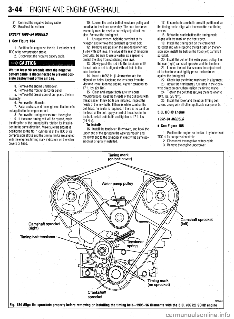
1. Position the engine so the No. 1 cylinder is at
TDC of its compression stroke.
2. Disconnect the negative battery cable.
3. Remove the engine undercover.
Timing mark
(on belt cover)
Timing belt tensioner
Crankshaft
sprocket
7923W :ig. 184 Align the sprockets properly before removing or installing the timing belt-1995-96 Diamante with the 3.OL (6672) SDHC engine
Page 108 of 408
ENGINEANDENGINEOVERHAUL 3-47
DO NOT rotate or turn the camshafts when re-
moving the sprockets or severe engine dam-
age will result from internal component in-
terference.
22. Align the mark on the crankshaft sprocket
with the mark on the front case. Then, move the
crankshaft sprocket 1 tooth counterclockwise.
23. Align the timing marks of the camshafts with
the marks on the rear covers.
24. Using large paper clips to secure the timing
belt to the sprockets, install the timing belt in the fol-
lowing order. Be sure camshafts-to-cylinder heads
and crankshaft-to-front cover timing marks are
aligned. Install the timing belt around the pulleys in
the following order:
a. Exhaust camshaft sprocket (front bank).
b. Intake camshaft sprocket (front bank).
c. Water pump pulley.
d. Intake camshaft sprocket (rear bank).
e. Exhaust camshaft sprocket (rear bank).
f. Tensioner pulley.
g. Crankshaft pulley.
h. Idler pulley.
*Since the camshaft sprockets turn easily,
secure them with box wrenches when in-
stalling the timing belt.
25. Align all timing marks on the crankshaft and
raise the tensioner pulley against the belt to remove
slack, snug tensioner bolt.
26. Check the alignment of all the timing marks
and remove the clips that secure the timing belt to the
camshaft sprockets.
27. Rotate the engine 1/4 turn counterclockwise,
then rotate the engine clockwise to align the timing
marks. Check that all the timing marks are in align-
ment.
28. Loosen the center bolt on the tensioner pul-
ley.
29. Using tool MD998752 or equivalent and a
torque wrench, apply 84 inch Ibs. (10 Nm) to the tool
on the tensioner. Tighten the tensioner bolt to 35 ft.
Ibs. (49 Nm) and be sure the tensioner does not ro-
tate with the bolt. 30. Rotate the crankshaft two complete turns
clockwise and let it sit for approximately five minutes.
Then, check that the set pin can easily be inserted
and removed from the hole in the auto-tensioner.
31. Remove the set wire attached to the auto-ten-
sioner
32. Measure the auto-tensioner protrusion (the
distance between the tensioner arm and auto-ten-
sioner body) to ensure that it is within 0.15-0.18 in.
(3.8-4.5mm). If out of specification, repeat adjust-
ment procedure until the specified value is obtained.
33. Check again that the timing marks on all
sprockets are in proper alignment.
34. Install the timing belt covers and all other ap-
plicable components.
3.51 Engine
p See Figure 187
1. Disconnect the negative battery cable.
2. Drain the cooling system.
Never open, service or drain the radiator or
cooling system when hot; serious burns can
occur from the steam and hot coolant. Also,
when draining engine coolant, keep in mind
that cats and dogs are attracted to ethylene
giycoi antifreeze and could drink any that is
left in an uncovered container or in puddles
on the ground. This will prove fatal in suffi-
cient quantities. Always drain coolant into a
sealable container. Coolant should be reused
unless it is contaminated or is several years
old.
3. Remove the drive belts.
4. Remove the upper radiator shroud.
5. Remove the fan and fan pulley.
6. Without disconnecting the lines, remove the
power steering pump from its bracket and position it
to the side Remove the pump brackets.
7. Remove the belt tensioner pulley bracket.
8. Without releasing the refrigerant, remove the
air conditioning compressor from its bracket and po-
sition it to the side.
9. Remove the bracket.
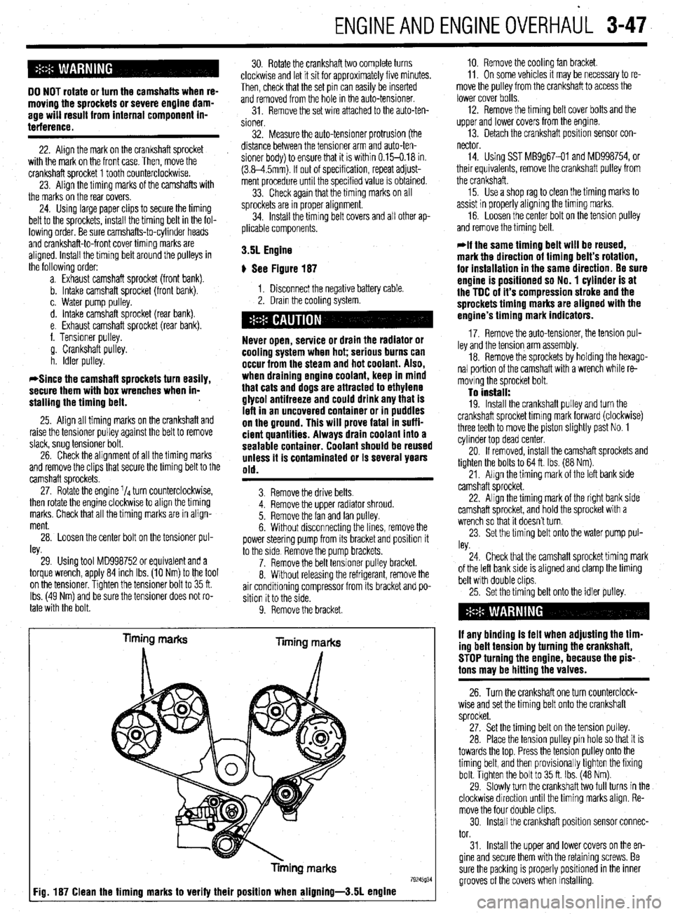
Timing marks
liming marks
Tinning marks
79245934 Fig. 187 Clean the timing marks to verify their position when aligning-3.51 engine
10. Remove the cooling fan bracket.
11, On some vehicles It may be necessary to re-
move the pulley from the crankshaft to access the
lower cover bolts.
12. Remove the timing belt cover bolts and the
upper and lower covers from the engme.
13. Detach the crankshaft position sensor con-
nector
14. Using SST MB9g67-01 and MD998754, or
their equivalents, remove the crankshaft pulley from
the crankshaft.
15. Use a shop rag to clean the timing marks to
assist in properly aligning the timing marks.
16. Loosen the center bolt on the tension pulley
and remove the timing belt.
@if the same timing belt will be reused,
mark the direction of timing belt’s rotation,
for installation in the same direction. Be sure
engine is positioned so No. 1 cylinder is at
the TDC of it’s compression stroke and the
sprockets timing marks are aligned with the
engine’s timing mark indicators.
17. Remove the auto-tensioner, the tension pul-
ley and the tension arm assembly.
18. Remove the sprockets by holding the hexago-
nal portion of the camshaft with a wrench while re-
moving the sprocket bolt.
To install: 19. Install the crankshaft pulley and turn the
crankshaft sprocket timing mark forward (clockwise)
three teeth to move the piston slightly past No. 1
cylinder top dead center.
20. If removed, install the camshaft sprockets and
tighten the bolts to 64 ft. Ibs. (88 Nm).
21, Align the timing mark of the left bank side
camshaft sprocket.
22. Align the timing mark of the right bank side
camshaft sprocket, and hold the sprocket with a
wrench so that it doesn’t turn.
23. Set the timing belt onto the water pump pul-
ley.
24. Check that the camshaft sprocket timing mark
of the left bank side is aligned and clamp the timing
belt with double clips.
25. Set the timing belt onto the idler pulley.
if any binding is felt when adjusting the tim-
ing belt tension by turning the crankshaft,
STOP turning the engine, because the pis-
tons may be hitting the valves.
26. Turn the crankshaft one turn counterclock-
wise and set the timing belt onto the crankshaft
sprocket.
27. Set the timing belt on the tension pulley.
28. Place the tension pulley pin hole so that it is
towards the top. Press the tension pulley onto the
timing belt, and then provisionally tighten the fixing
bolt. Tighten the bolt to 35 ft. Ibs. (48 Nm).
29. Slowly turn the crankshaft two full turns in the
clockwise direction until the timing marks align. Re-
move the four double clips.
30. Install the crankshaft position sensor connec-
tor.
31. Install the upper and lower covers on the en-
gine and secure them with the retaining screws. Be
sure the packing is properly positioned in the inner
grooves of the covers when installing.
Page 109 of 408
.
3-48 ENGINEANDENGINEOVERHAUL
32. Install the crankshaft pulley if it was removed.
Tighten the bolt to 110 ft. Ibs. (150 Nm).
33. Install the air conditioning bracket and com-
pressor on the engine. Install the belt tensioner.
34. Install the power steering pump into position.
Install the fan pulley and fan.
35. Install the fan shroud on the radiator.
36. Refill the cooling system.
I
37. Connect the negative battery cable.
38. Start the enaine and check for fluid leaks.
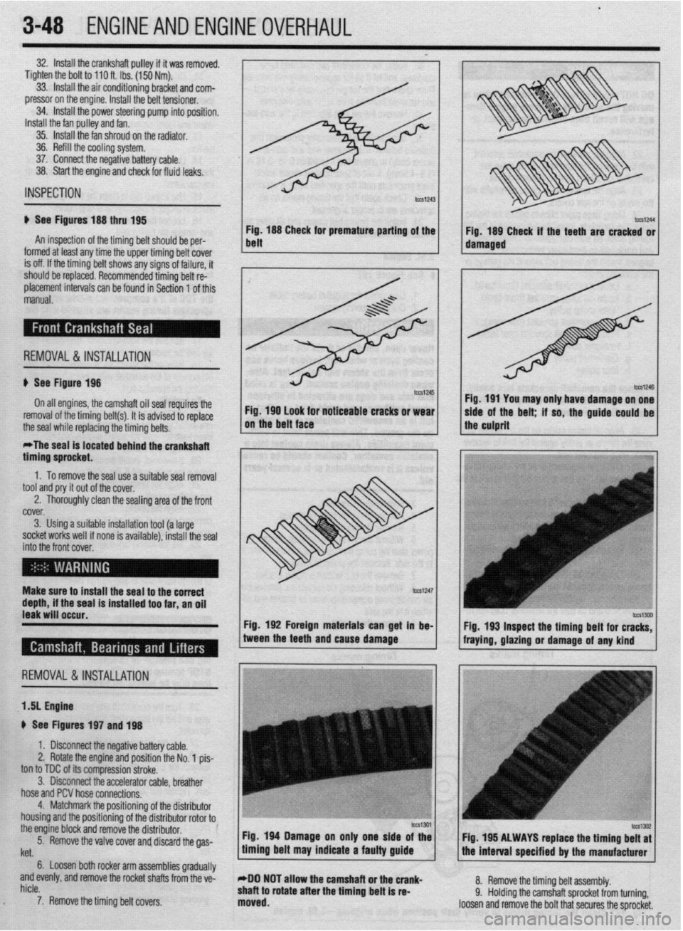
Fig. 188 CI ’ m
belt neeK ror premature panrng of the
Fig. 189 Check if the teeth are cracked or
IUIIII~U at IWSI
arly me me upper ommg oerr cover 1 1 damaged ,
I
is off. If the timina belt shows anv sians of failure. it INSPECTION
ti See Figures 188 thru 195
An inspection of the timing belt should be per-
I ^__^ -I ^I I---.-- I.-. II. .- I. . I I.
should be replaced. Recommended timing belt re:
placement intervals can be found in Section 1 of this
manual.
; REMOVAL&INSTALLATION
u See Figure 198
On all engines, the camshaft oil seal repuires the
Fig. 190 look for noticeable cracks or wear
removal of the timing belt(s). It is advised to replace
the seal while replacing the timing belts. on the belt face
*The seal is located behind the crankshaft
timino sorocket. I I Fig. 191 You may only have damage on one
side of the belt; if so, the guide-could be 1
the culprit
” .
1. To remove the seal use a suitable seal removal
tool and pry it out of the cover.
2. Thoroughly clean the sealing area of the front
fYi”f.V
i ““.“I. 3. Using a suitable installation tool (a large
socket works well if none is available), install the seal
into thr ? front cover,
EnI
Make surf! to install the seal to the correct
depth, if the seal is installed too far, an oil
leak will occur.
Fig. 192 Foreign materials can get in be-
REMOVAL &INSTALLATION
1 .!I Engine
+ See Figures 197 and 198
1. Disconnect the negative battery cable.
2. Rotate the engine and position the No. 1 pis-
ton to TDC of its compression stroke.
3. Disconnect the accelerator cable, breather
hose and PCV hose connections.
4. Matchmark the positionino of the distributor
housing and the positioning of thedistributor rotor to0
the engine block and remove the distributor.
5.
. Remove the valve cover and discard the gas- tween the teeth and cause damage
fraying, gla&g or damage of any kind
’
Itet.
6. Loosen both rocker arm assemblies gradually
and evenly, and remove the rocket shafts from the ve-
hicle.
7. Remove the timing belt covers.
c
Fig 194 Damage on only one side of the
timing belt may indicate a faulty guide Fig. 195 ALWAYS raplace the timing belt at
the interval soecified br the manufacturer
*DO NOT allow the camshaft or the crank-
shaft to rotate after the timing belt is re-
moved. 8. Remove the timing belt assembly.
9. Holding the camshaft sprocket from turning,
loosen and remove the bolt that secures the sprocket.
Page 110 of 408
ENGINEANDENGINEOVERHAUL 3-49
011 pump
MS8
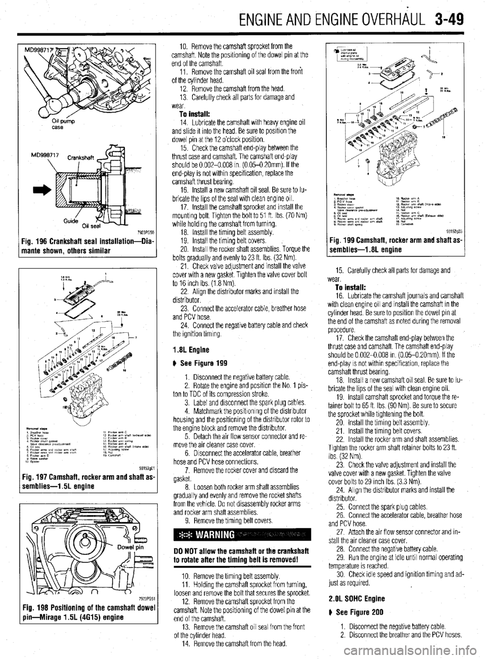
7923PG51 Fig. 196 Crankshaft seal installation-Dia
mante shown, others similar
:ig. 197 Camshaft, rocker arm and shaft as
remblies-1.5L engine
7923PG5 Fig. 198 Positioning of the camshaft dowe
pin-Mirage 1.5L (4615) engine
10. Remove the camshaft sprocket from the
camshaft. Note the positioning of the dowel pin at the
end of the camshaft.
11. Remove the camshaft oil seal from the front
of the cylinder head.
12. Remove the camshaft from the head.
13. Carefully check all parts for damage and
wear
To install:
14. Lubricate the camshaft with heavy engine oil
and slide it mto the head. Be sure to position the
dowel pin at the 12 o’clock position.
15. Check the camshaft end-play between the
thrust case and camshaft. The camshaft end-play
should be 0.002-0.008 m (0.05-O 20mm). If the
end-play is not within specification, replace the
camshaft thrust bearing.
16 Install a new camshaft oil seal. Be sure to Iu-
bricate the lips of the seal with clean engine 011.
17. Install the camshaft sprocket and install the
mountrng bolt. Tighten the bolt to 51 ft. Ibs. (70 Nm)
while holding the camshaft from turning.
18. Install the timing belt assembly.
19. Install the timing belt covers.
20. Install the rocker shaft assemblies. Torque the
bolts gradually and evenly to 23 ft. Ibs. (32 Nm).
21. Check valve adjustment and install the valve
cover with a new gasket. Tighten the valve cover bolt
to 16 inch Ibs (1.8 Nm).
22 Align the distributor marks and install the
distributor.
23. Connect the accelerator cable, breather hose
and PCV hose.
24. Connect the negative battery cable and check
the ignition timing
1.8L Engine
# See Figure 199
1. Disconnect the negative battery cable
2. Rotate the engine and position the No. 1 pis-
ton to TDC of its compression stroke.
3. Label and disconnect the spark plug cables.
4. Matchmark the positronrng of the distributor
housing and the positioning of the distributor rotor to
the engine block and remove the distributor.
5. Detach the air flow sensor connector and re-
move the air cleaner case cover.
6. Drsconnect the accelerator cable, breather
hose and PCV hose connections.
7. Remove the rocker cover and discard the
gasket.
8. Loosen both rocker arm shaft assemblies
gradually and evenly and remove the rocket shafts
from the vehicle. Do not disassembly rocker arms
and rocker arm shaft assemblies.
9. Remove the timing belt covers.
DO NOT allow the camshaft or the crankshaft
to rotate after the timing belt is removed!
10. Remove the timing belt assembly.
11. Holding the camshaft sprocket from turning,
loosen and remove the bolt that secures the sprocket.
12. Remove the camshaft sprocket from the
camshaft. Note the positioning of the dowel pin at the
end of the camshaft.
13. Remove the camshaft oil seal from the front
of the cylinder head.
14. Remove the camshaft from the head.
(r.mblies-1.8L Agine g3i53033 Fig 199 Camshaft rocker arm and shaft as-
15. Carefully check all parts for damage and
wear.
To install:
16. Lubricate the camshaft journals and camshaft
with clean engine oil and install the camshaft in the
cylinder head. Be sure to position the dowel pin at
the end of the camshaft as noted during the removal
procedure.
17. Check the camshaft end-play between the
thrust case and camshaft The camshaft end-play
should be 0.002-0.008 in. (0.05-0.20mm). If the
end-play
IS not within specification, replace the
camshaft thrust bearing
18. Install a new camshaft oil seal. Be sure to Iu-
bricate the lips of the seal with clean engine oil.
19. Install camshaft sprocket and torque the re-
tainer bolt to 65 ft. Ibs. (90 Nm). Be sure to secure
the sprocket while tightening the bolt.
20 Install the timing belt assembly.
21. Install the timing belt covers.
22. Install the rocker arm and shaft assemblies.
Tighten the rocker arm shaft retainer bolts to 23 ft.
Ibs (32 Nm).
23 Check the valve adjustment and install the
valve cover with a new gasket. Tighten the valve
cover bolts to 29 inch Ibs. (3.3 Nm).
24. Align the distributor marks and install the
distributor.
25. Connect the spark plug cables.
26. Connect the accelerator cable, breather hose
and PCV hose.
27. Attach the air flow sensor connector and in-
stall the air cleaner case cover.
28. Connect the negative battery cable.
29. Run the engine at idle until normal operating
temperature is reached.
30. Check idle speed and ignition timing and ad-
just as required.
2.OL SDHC Engine
# See Figure 200
1. Disconnect the negative battery cable.
2. Disconnect the breather and the PCV hoses
Page 111 of 408
.
3-50 ENGINEANDENGINEOVERHALJL
F
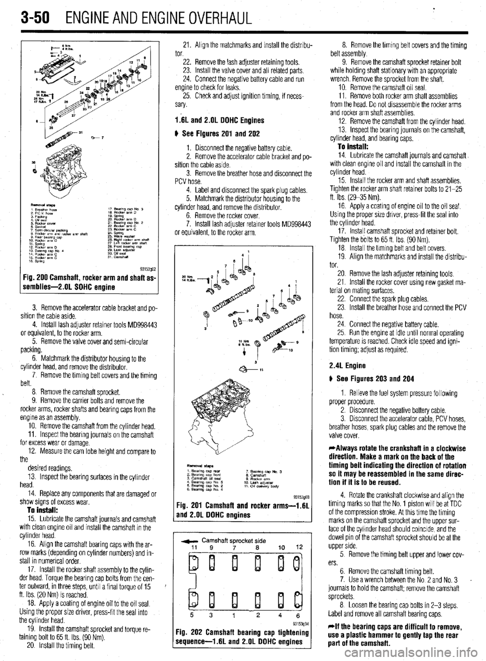
1 s 93153QO2 :ig. 200 Camshaft, rocker arm and shaft as-
iemblies-2.01 SOHC ermine
3. Remove the accelerator cable bracket and po-
sition the cable aside.
4. Install lash adjuster retainer tools MD998443
or equivalent, to the rocker arm.
5. Remove the valve cover and semi-circular
packing.
6. Matchmark the distributor housing to the
cylinder head, and remove the distributor,
7. Remove the timing belt covers and the timing
belt.
8 Remove the camshaft sprocket.
9. Remove the carrier bolts and remove the
rocker arms, rocker shafts and bearing caps from the
engine as an assembly.
10. Remove the camshaft from the cylinder head.
11. Inspect the bearing journals on the camshaft
for excess wear or damage.
12. Measure the cam lobe height and compare to
the
desired readings.
13. Inspect the bearing surfaces in the cylinder
head.
14. Replace any components that are damaged or
show signs of excess wear,
To install:
15. Lubricate the camshaft journals and camshaft
with clean engine oil and install the camshaft in the
cylinder head.
16. Align the camshaft bearing caps with the ar-
row marks (depending on cylinder numbers) and in-
stall in numerical order,
17. Install the rocker shaft assembly to the cylin-
der head. Torque the bearing cap bolts from the cen-
ter outward, in three steps, unh a final torque of 15
ft. Ibs. (20 Nm) is reached.
18. Apply a coating of engine oil to the oil seal.
Using the proper size driver, press-frt the seal into
the cylinder head.
19. install the camshaft sprocket and torque re-
taining bolt to 65 ft. Ibs. (90 Nm).
20. Install the timing belt. 21. Ahgn the matchmarks and install the distrrbu- 8. Remove the timing belt covers and the timing
tor. belt assembly.
22. Remove the lash adjuster retaining tools.
23. Install the valve cover and all related parts
24. Connect the negative battery cable and run
engine to check for leaks,
25. Check and adjust ignition timing, if neces-
sary.
l.‘6L and 2.lJL DOHC Engines
6 See Figures 201 and 202
1. Disconnect the negative battery cable.
2. Remove the accelerator cable bracket and po-
sition the cable aside.
3. Remove the breather hose and disconnect the
PCV hose. 9. Remove the camshaft sprocket retainer bolt
while holding shaft stationary with an appropriate
wrench. Remove the sprocket from the shaft.
10. Remove the camshaft oil seal.
11. Remove both rocker arm shaft assemblies
from the head. Do not drsassemble the rocker arms
and rocker arm shaft assemblies.
12. Remove the camshaft from the cylinder head.
13. inspect the bearing journals on the camshaft,
cylinder head, and bearing caps.
To install:
14. Lubricate the camshaft journals and camshaft
with clean engine oil and install the camshaft in the
cylinder head.
4. Label and disconnect the spark plug cables.
5. Matchmark the distributor housing to the
cylinder head, and remove the distributor.
6. Remove the rocker cover.
7. Install lash adjuster retarner tools MD998443
or equivalent, to the rocker arm. 15. Install the rocker arm and shaft assemblies.
Tighten the rocker arm shaft retainer bolts to 21-25
ft. Ibs. (2935 Nm).
16 Apply a coating of engine oil to the oil seal.
Using the proper size driver, press-fit the seal into
the cylinder head.
17. Instal! camshaft sprocket and retainer bolt.
Tighten the bolts to 65 ft. Ibs. (90 Nm).
18. Install the hming belt and belt covers.
19. Align the matchmarks and install the distribu-
tor.
93153gO: :ig. 201 Camshaft and rocker arms-i.61
rnd 2.OL DOHC engines
r ,
w Camshaft sprocket side
ei i i ij
20. Remove the lash adjuster retaining tools,
21. Install the rocker cover using new gasket ma-
terial on mating surfaces,
22. Connect the spark plug cables.
23. Install the breather hose and connect the PCV
hose.
24. Connect the negative battery cable.
25. Run the engme at idle until normal operating
temperature is reached. Check idle speed and igni-
tion timing; adjust as required.
2.4L Engine
) See Figures 203 and 204
1. Relieve the fuel system pressure following
proper procedure.
2. Disconnect the negative battery cable.
3. Disconnect the accelerator cable, PCV hoses,
breather hoses, spark plug cables and the remove the
valve cover.
*Always rotate the crankshaft in a clockwise
direction. Make a mark on the back of the
timing belt indicating the direction of rotation
so it may be reassembled in the same direc-
tion if it is to be reused.
4. Rotate the crankshaft clockwise and align the
timing marks so that the No. 1 piston will be at TDC
of the compression stroke. At this time the timing
marks on the camshaft sprocket and the upper sur-
face of the cyhnder head should coincide, and the
dowel pin of the camshaft sprocket should be at the
upper side.
5 Remove the timing belt upper and lower cov-
ers.
6. Remove the camshaft timing belt.
7. Use a wrench between the No 2 and No. 3
journals to hold the camshaft; remove the camshaft
sprockets.
8 Loosen the bearing cap bolts in 2-3 steps.
Label and remove all camshaft bearing caps,
*If the bearing caps are difficult to remove,
use a plastic hammer to gently tap the rear
part of the camshaft.
Page 112 of 408
ENGlNEANDENGlNEOVERHALiL 3-51
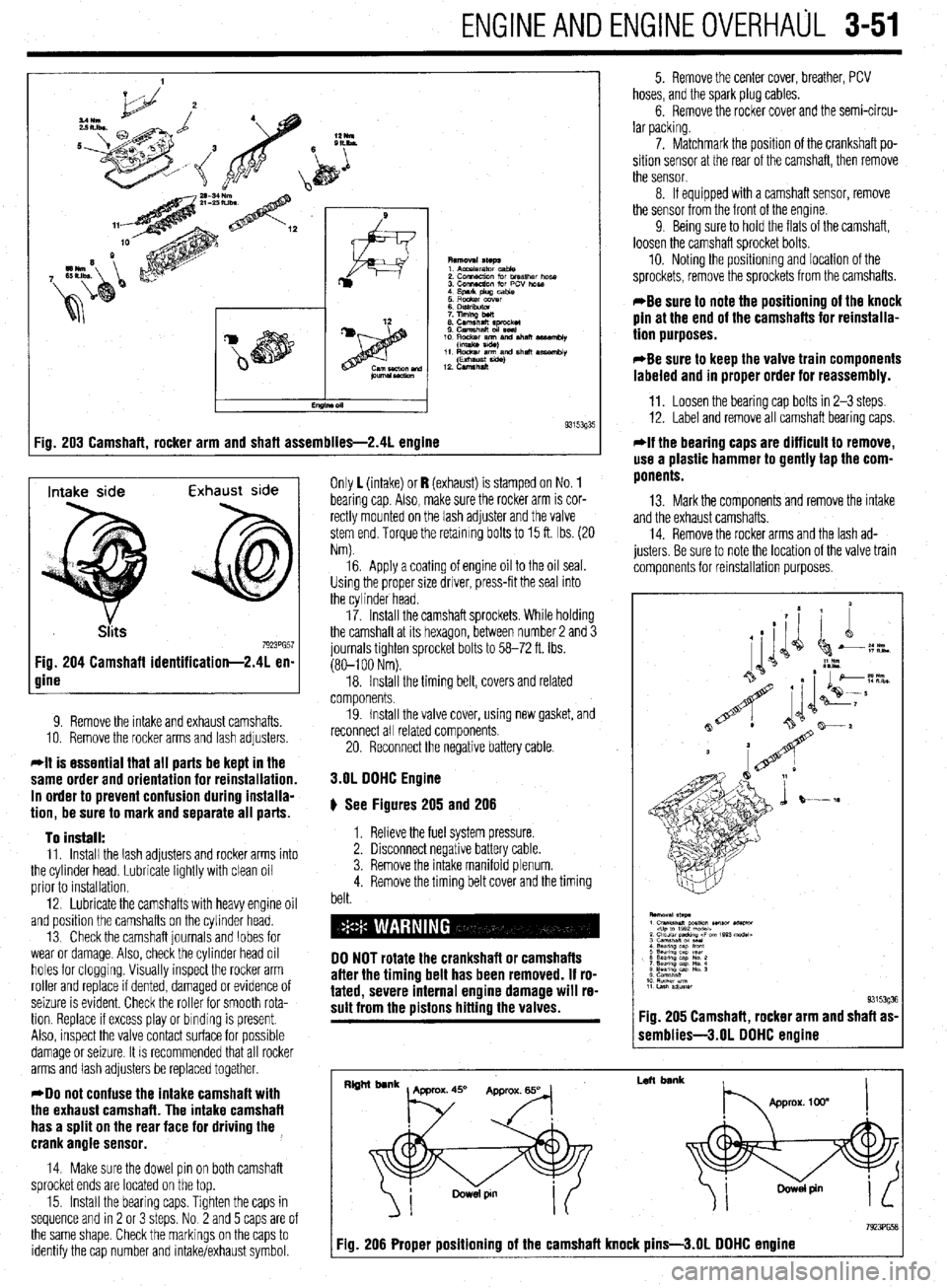
:ig. 203 Camshaft, rocker arm and shaft assemblies-2.41 engine 9315393'
Intake side Exhaust side
7923PG57 Fig. 204 Camshaft identification-2.41 en-
gine
9. Remove the intake and exhaust camshafts.
10. Remove the rocker arms and lash adjusters
*It is essential that all parts be kept in the
same order and orientation for reinstallation.
In order to prevent confusion during installa-
tion, be sure to mark and separate all parts.
To install:
11. Install the lash adjusters and rocker arms into
the cylinder head. Lubricate lightly with clean oil
prior to installation.
12. Lubricate the camshafts with heavy engine oil
and position the camshafts on the cylinder head.
13 Check the camshaft journals and lobes for
wear or damage. Also, check the cylinder head oil
holes for clogging. Visually inspect the rocker arm
roller and replace if dented, damaged or evidence of
seizure is evident. Check the roller for smooth rota-
tion. Replace If excess play or binding is present.
Also, inspect the valve contact surface for possible
damage or seizure. It is recommended that all rocker
arms and lash adjusters be replaced together.
*Do not confuse the intake camshaft with
the exhaust camshaft. The intake camshaft
has a split on the rear face for driving the ,
crank angle sensor.
14. Make sure the dowel pin on both camshaft
sprocket ends are located on the top.
15. Install the bearing caps. Tighten the caps in
sequence and rn 2 or 3 steps. No 2 and 5 caps are of
the same shape. Check the markings on the caps to
identify the cap number and intake/exhaust symbol. Only 1 (intake) or I? (exhaust) is stamped on No. 1
bearing cap Also, make sure the rocker arm is cor-
rectly mounted on the lash adjuster and the valve
stem end. Torque the retaining bolts to 15 ft. Ibs. (20
Nm).
16. Apply a coating of engine oil to the oil seal.
Using the proper size driver, press-fit the seal into
the cylinder head.
17. Install the camshaft sprockets. While holding
the camshaft at its hexagon, between number 2 and 3
journals tighten sprocket bolts to 58-72 ft. Ibs.
(80-l 00 Nm).
18. Install the timing belt, covers and related
components.
19. Install the valve cover, using new gasket, and
reconnect all related components
20. Reconnect the negative battery cable.
3.OL DOHC Engine
# See Figures 205 and 206
1. Relieve the fuel system pressure.
2. Disconnect negative battery cable.
3. Remove the intake manifold plenum.
4. Remove the timing belt cover and the timing
belt.
DO NOT rotate the crankshaft or camshafts
after the timing belt has been removed. If ro-
tated, severe internal engine damage will re-
sult from the pistons hitting the valves.
5. Remove the center cover, breather, PCV
hoses, and the spark plug cables.
6. Remove the rocker cover and the semi-circu-
lar packing.
7. Matchmark the position of the crankshaft po-
sition sensor at the rear of the camshaft, then remove
the sensor.
8. If equipped with a camshaft sensor, remove
the sensor from the front of the engine.
9 Being sure to hold the flats of the camshaft,
loosen the camshaft sprocket bolts.
10. Noting the positionmg and location of the
sprockets, remove the sprockets from the camshafts.
*Be sure to note the positioning of the knock
pin at the end of the camshafts for reinstalla-
tion purposes.
*Be sure to keep the valve train components
labeled and in proper order for reassembly.
11. Loosen the bearing cap bolts in 2-3 steps.
12. Label and remove all camshaft bearing caps.
*If the bearing caps are difficult to remove,
use a plastic hammer to gently tap the com-
ponents.
13. Mark the components and remove the intake
and the exhaust camshafts.
14. Remove the rocker arms and the lash ad-
justers. Be sure to note the location of the valve train
components for reinstallation purposes.
1 semblies-3.01 DOHC engine
I
Left bank
7923PG58 Fig. 206 Proper positioning of the camshaft knock pins-3.01 DOHC engine