1900 MITSUBISHI DIAMANTE check engine light
[x] Cancel search: check engine lightPage 192 of 408
FUEL SYSTEM 5-5,
21. Connect the negative battery cable. Refill the
cooling system.
REMOVAL & INSTALLATION
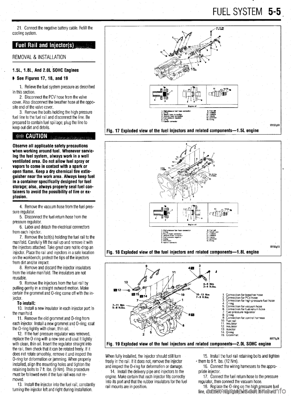
1.5L, 1.8L, And 2.OL SOHC Engines
ti See Figures 17, 18, and 19
1. Relieve the fuel system pressure as described
in this section.
2. Disconnect the PCV hose from the valve
cover. Also disconnect the breather hose at the oppo-
site end of the valve cover.
3. Remove the bolts holding the high pressure
fuel line to the fuel rail and disconnect the line. Be
prepared to contain fuel spillage; plug the line to
keep out dirt and debris.
Observe all applicable safety precautions
when working around fuel. Whenever servic-
ing the fuel system, always work in a well
ventilated area. 00 not allow fuel spray or
vapors to come in contact with a spark or
open flame. Keep a dry chemical fire extin-
guisher near the work area. Always keep fuel
in a container specifically designed for fuel
storage; also, always properly seal fuel con-
tainers to avoid the possibility of fire or ex-
plosion.
4. Remove the vacuum hose from the fuel pres-
sure regulator.
5. Disconnect the fuel return hose from the
pressure regulator.
6. Label and detach the electrical connectors
from each injector.
7. Remove the bolt(s) holding the fuel rail to the
manifold. Carefully lift the rail up and remove it with
the injectors attached. Take great care not to drop an
injector Place the rail and Injectors in a safe location
on the workbench; protect the tips of the injectors
from dirt and/or Impact.
8. Remove and discard the injector rnsulators
from the intake manifold. The insulators are not
reusable.
9. Remove the injectors from the fuel rail by
pulling gently in a straight outward motion. Make
certain the grommet and O-ring come off with the in-
jector.
To install: 10. Install a new insulator in each injector port in
the manifold.
11. Remove the old grommet and O-ring from
each injector Install a new grommet and O-ring; coat
the O-ring lightly with clean, thin oil.
12. If the fuel pressure regulator was removed,
replace the O-ring with a new one and coat it lightly
with clean, thin oil Insert the regulator straight into
the rail, then check that it can be rotated freely. If It
does not rotate smoothly, remove it and inspect the
O-ring for deformation or jamming. When properly
installed, align the mounting holes and tighten the
retaining bolts to 7 ft. Ibs. (9 Nm). This procedure
must be followed even if the fuel rail was not re-
moved.
13. Install the injector into the fuel rail, constantly
turning the injector left and right during installation.
1Hilt4naunfu(norc e Fu(l
:E%!,,.,.- 1: IEE
: Efgz tz!z? :: %%I
;P&.xmeaw 13 m
Fig. 17 Exploded view of the fuel injectors and related components-l .5L engine
I
.xs.
1 Connection for breather hose
2 Connection for PCV hose
3 Connection for high tm?ss”re fuel hose
4 0-ring
5 Connection for vacuum hose
6 Connecr~on for fuel return hose
7 Fuel pressure regulator
8 0-ring
9 Connection for control harness
10 Fuel ml
11 Insulator
12 insulator
13 lnlector
14 O-ring
15 Grommet
89575026
Fig. 19 Exploded view of the fuel injectors and related components-2.01 SOHC engine
When fully installed, the injector should still turn
freely in the rail. If it does not, remove the injector
and inspect the O-ring for deformation or damage.
14. Install the delivery pipe and injectors to the
engine. Make certain that each injector fits correctly
into its port and that the rubber insulators for the fuel
rail mounts are in position. 15. Install the fuel rail retaining bolts and tighten
* them to 9 ft. Ibs. (12 Nm).
16. Connect the wiring harnesses to the appro-
priate injector.
17. Connect the fuel return hose to the pressure
regulator, then connect the vacuum hose.
18. Replace the O-ring on the high pressure fuel
line, coat the O-ring lightly with clean, thin oil and
Page 193 of 408
install the line to the fuel rail. Tighten the mounting
bolts,
19. Attach the PCV hose and the breather hose if
thev were disconnected.
20. Connect the negative battery cable. Pressur-
ize the fuel system and inspect all connections for
I
leaks.
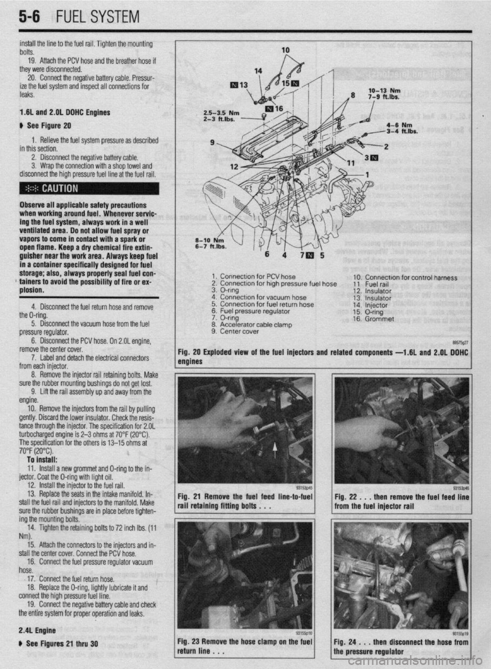
1.6L and 2.01 DOHC Engines
b See Figure 20
1. Relieve the fuel system pressure as described
in this section.
2. Disconnect the negative battery cable.
3. Wrap the connection with a shop towel and
disconnect the high pressure fuel line at the fuel rail.
Observe all applicable safety precautions
when working around fuel. Whenever servic-
ing the fuel system, always work in a well
ventilated area. Do not allow fuel spray or
vapors to come in contact with a spark or
open flame. Keep a dry chemical fire extin-
guisher near the work area. Always keep fuel
in a container specifically designed for fuel
storage; also, always properly seal fuel con-
* tainers to avoid the possibility of fire or ex-
plosion.
4. Disconnect the fuel return hose and remove
the O-ring.
5. Disconnect the vacuum hose from the fuel
pressure regulator.
6. Disconnect the PCV hose. On 2.OL engine,
remove the center cover.
1 x Connection for PCV hose
2. Connection for high pressure fuel hose
3. O-ring
4. Connection for vacuum hose
5. Connection for fuel return hose
&2 I=, 1c.1 nrncc*.ra regu,ator
lble clamD
7. Label and detach the electrical connectors
from each iniector.
8. Accelerator ca
9. Center cover . 10. Connection for control harness
11 Fuel rail
12. Insulator
13. Insulator
14. Injector
15. O-ring
16. Grommet
89575g27 Exploded view of the fuel injectors and related
components -1.6L and 2.QL DOHC
5-6 FUELSYSTEM
8. Remove the injector rail retaining bolts, Make
sure the rubber mounting bushings do not get lost.
9. Lift the rail assembly up and away from the
engine.
10. Remove the injectors from the rail by pulling
gently. Discard the lower insulator. Check the resis-
tance through the injector. The specification for 2.OL
turbocharged engine is 2-3 ohms at 70°F (20°C).
The specification for the others is 13-15 ohms at
70°F (20°C). To install:
11. Install a new grommet and O-ring to the in-
jector. Coat the O-ring with light oil.
12. install the injector to the fuel rail.
13. Replace the seats in the intake manifold. In-
stall the fuel rail and injectors to the manifold. Make
sure the rubber bushings are in place before tighten-
ing the mounting bolts.
14. Tighten the retaining bolts to 72 inch lbs. (11
Nm).
Fig. 21 Remove the fuel feed line-to-fuel
rail retaining fitting bolts . . .
15. Attach the connectors to the injectors and in-
stall the center cover. Connect the PCV hose.
16. Connect the fuel pressure regulator vacuum
hose.
17. Connect the fuel return hose.
18. Replace the O-ring, lightly lubricate it and
connect the high pressure fuel line.
19. Connect the negative battery cable and check
the entire system for proper operation and leaks. Fig. 22 . . . then remove the fuel feed line
from the fuel injector rail
2.4L Engine
b See Figures 21 thru 30
Page 194 of 408
FUELSYSTEM 5-7
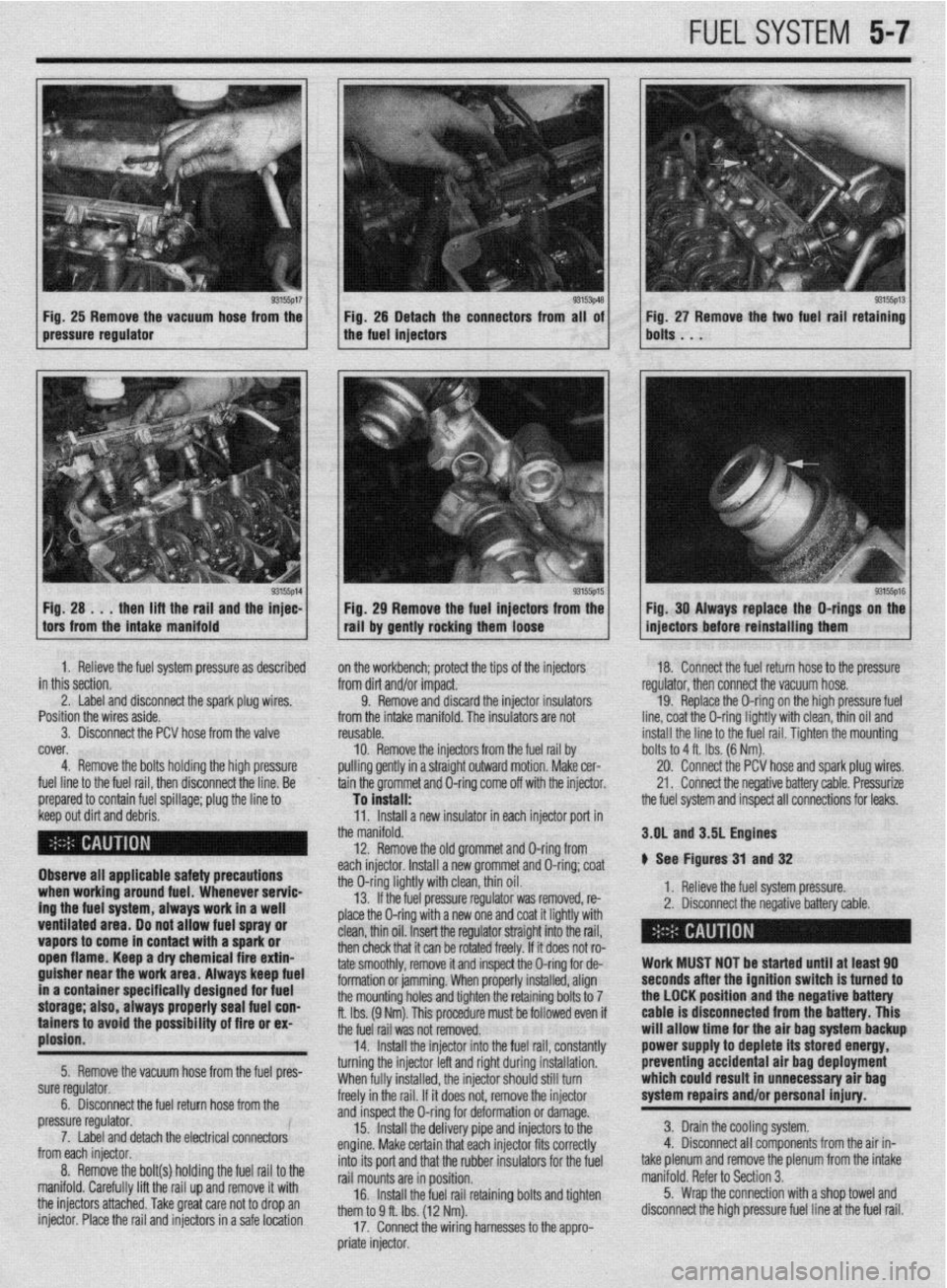
Fig, 25 Remove the vacuum hose from the Fig. 25 Detach the connectors from all of
pressure regulator the fuel injectors
1 H; :A ..;lt;;aft~rgi,i~;yl the ;F: 1 / . 93155p15 1 Fig 29 Remove the fuel injectors from the
tall by gently rocking them loose Fig. 27 Remove the two fuel rail retaining
bolts . . .
93155ps Fig. 30 Always replace the O-rings on the
injectors before reinstalling them
1. Relieve the fuel system pressure as described
in this section.
2. Label and disconnect the spark plug wires. ’
Position the wires aside.
3. Disconnect the PCV hose from the valve
cover,
4. Remove the bolts holding the high pressure
fuel line to the fuel rail, then disconnect the line. Be
prepared to contain fuel spillage; plug the line to on the workbench; protect the tips of the injectors
from dirt and/or impact.
9. Remove and discard the injector insulators
from the intake manifold. The insulators are not
reusable.
10. Remove the injectors from
pulling gently in a straight outwarc the fuel rail by
I motion. Make cer-
tain the grommet and O-ring come off with the injector. 18. Connect the fuel return hose to the pressure
regulator, then connect the vacuum hose.
19. Replace the O-ring on the high pressure fuel
line, coat the O-ring lightly with clean, thin oil and
install the line to the fuel rail. Tiahten the mountina
To install: -
the fuel system and inspect all connections for leaks. bolts to 4 ft. Ibs. (6 Nm).
20. Connect the PCV hose and spark plug wires.
21. Connect the negative battery cable. Pressurize
1. neneve me rueI system pressure.
2. Disconnect the negative battery cable. 3.OL and 3.5L Engines
# See Figures 31 and 32
> - ,. .* , ,
I
I
Work MUST NOT be started until at least 90
seconds after the ignition switch is turned to
the LOCK position and the negative battery
cable is disconnected from the battery. This
will allow time for the air bag system backup
power supply to deplete its stored energy,
preventing accidental air bag deployment
which could result in unnecessary air bag
system repairs and/or personal injury.
3. Drain the cooling system.
4. Disconnect all components from the air in-
take plenum and remove the plenum from the intake
manifold. Refer to Section 3.
5. Wrap the connection with a shop towel and
disconnect the high pressure fuel line at the fuel rail. keep out dirt and debris.
Observe all applicable safety precautions
when working around fuel. Whenever servic-
ing the fuel system, always work in a well
ventilated area. Do not allow fuel spray or
vapors to come in contact with a spark or
open flame. Keep a dry chemical fire extin-
guisher near the work area. Always keep fuel
in a container specifically designed for fuel
storage; also, always properly seal fuel con-
tainers to avoid the possfbility of fire or ex-
plosion.
5. Remove the vacuum hose from the fuel pres-
sure regulator.
6. Disconnect the fuel return hose from the
pressure regulator.
7. Label and detach the electrical connectors
from each injector.
8. Remove the bolt(s) holding the fuel rail to the
manifold. Carefully lift the rail up and remove it with
the injectors attached. Take great care not to drop an
injector. Place the rail and injectors in a safe location 11. Install a new insulator in each injector port in
the manifold.
12. Remove the old grommet and D-ring from
each injector. Install a new grommet and O-ring; coat
the O-ring lightly with clean, thin oil.
13. If the fuel pressure regulator was removed, re-
place the O-ring with a new one and coat it lightly with
clean, thin oil. Insert the regulator straight into the rail,
then check that it can be rotated freely. If it does not ro-
tate smoothly, remove it and inspect the O-ring for de-
formation or jamming. When properly installed, align
the mounting holes and tighten the retaining bolts to 7
ft. Ibs. (9 Nm). This procedure must be followed even if
the fuel rail was not removed.
14. Install the injector into the fuel rail, constantly
turning the injector left and right during installation.
When fully installed, the injector should still turn
freely in the rail. If it does not, remove the injector
and inspect the O-ring for deformation or damage.
15. Install the delivery pipe and injectors to the
engine. Make certain that each injector fits correctly
into its port and that the rubber insulators for the fuel
rail mounts are in position.
16. Install the fuel rail retaining bolts and tighten
them to 9 ff. Ibs. (12 Nm).
17. Connect the wiring harnesses to the appro-
priate injector.
Page 195 of 408
5-8 FUELSYSTEM
9 ,npimr w1m.m
1: i”“L,
1: 82”w
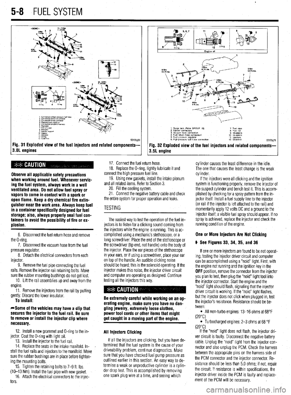
93155gx Fig. 31 Exploded view of the fuel injectors and related components-
s.OL engines
Observe all applicable safety precautions
when working around fuel. Whenever servic-
ing the fuel system, always work in a well
ventilated area. Do not allow fuel spray or
vapors to come in contact with a spark or
open flame. Keep a dry chemical fire extin-
guisher near the work area. Always keep fuel
in a container specifically designed for fuel
storage; also, always properly seal fuel con-
tainers to avoid the possibility of fire or ex-
plosion.
6. Disconnect the fuel return hose and remove
the O-ring.
7. Disconnect the vacuum hose from the fuel
pressure regulator.
8. Detach the electrical connectors from each
injector.
9. Remove the fuel pipe connectmg the fuel
rails. Remove the injector rail retaining bolts. Make
sure the rubber mounting bushings do not get lost.
10. Lift the rail assemblies up and away from the
engine.
11. Remove the injectors from the rail by pulling
gently. Discard the lower insulator.
To install:
*Some of the vehicles may have a clip that
secures the injector to the fuel rail. Be sure
to remove or install the injector clip where
necessary.
12. Install a new grommet and O-ring to the in-
jector. Coat the O-ring with light oil.
13. Install the injector to the fuel rail.
14. Replace the seats in the intake manifold. In-
stall the fuel rails and injectors to the manifold. Make
sure the rubber bushings are in place before tighten-
ing the mounting bolts.
15. Tighten the retaining bolts to 7-9 ft. Ibs.
(W-13 Nm) Install the fuel pipe with new gasket.
16. Attach the electrical connectors to the injec-
tors
Fig. 32 Exploded view of the fuel injectors and related components-
3.5L engine
17. Connect the fuel return hose.
18. Replace the O-ring, lightly lubricate it and
connect the high pressure fuel line.
19. Usmg new gaskets, install the intake plenum
and all related items. Refer to Section 3.
20. Fill the cooling system.
21. Connect the negative battery cable and check
the entire system for proper operation and leaks.
The easiest way to test the operation of the fuel in-
jectors is to listen for a clicking sound coming from
the injectors while the engine IS running. This is ac-
complished using a mechanic’s stethoscope, or a
long screwdriver. Place the end of the stethoscope or
the screwdriver (tip end, not handle) onto the body of
the injector. Place the ear pieces of the stethoscope
in your ears, or if using a screwdriver, place your ear
on top of the handle. An audible chcking noise
should be heard; this is the solenoid operating. If the
injector makes this noise, the injector driver circuit
and computer are operating as designed. Continue
testing all the injectors this way.
Be extremely careful while working on an op-
erating engine, make sure you have no dan-
gling jewelry, extremely loose clothes,
power tool cords or other items that might
get caught in a moving part of the ermine.
All Injectors Clicking
If all the injectors are clicking, but you have de-
termined that the fuel system is the cause of your
driveability problem, continue diagnostics. Make
sure that you have checked fuel pump pressure as
outlined earlier in this section. An easy way to de-
termine a weak or unproductive cylinder is a cylin-
der drop test. This is accomplished by removing
one spark plug wire at a time, and seeing which cylinder causes the least difference in the idle.
The one that causes the least change is the weak
cylinder.
If the injectors were all clicking and the ignition
system is functioning properly, remove the injector of
the suspect cylinder and bench test it. This is accom-
plished by checking for a spray pattern from the in-
jector itself Install a fuel supply line to the injector
(or rail if the injector is left attached to the rail) and
momentarily apply 12 volts DC and a ground to the
injector itself; a visible fuel spray should appear. If no
spray is achieved, replace the injector and check the
running condition of the engine.
One or More Injectors Are Not Clicking
6 See Figures 33, 34, 35, and 36
If one or more injectors are found to be not operat-
ing, testing the injector driver circuit and computer
can be accomplished using a “noid” light. First, with
the engine not running and the ignition key in the
OFF position, remove the connector from the injector
you plan to test, then plug the “noid” light tool into
the injector connector. Start the engine and the
“noid” light should flash, signaling that the injector
driver circuit is working. If the “noid” light flashes,
but the injector does not click when plugged in, test
the injectors resistance. Resistance should be be-
tween:
l All non-turbo engines: 13-16 ohms at 68°F
(20°C)
l Turbocharged engines: 2-3 ohms at 68 “F
(20°C)
If the “noid” light does not flash, the injector dri-
ver circuit is faulty. Disconnect the negative battery
cable. Unplug the “noid” light from the injector con-
nector and also unplug the PCM. Check the harness
between the appropriate pins on the harness side of
the PCM connector and the injector connector. Re-
sistance should be less than 5.0 ohms; if not, repair
the circuit. If resistance
IS within specifications, the
injector driver inside the PCM is faulty and replace-
ment of the PCM will be necessary.
Page 200 of 408
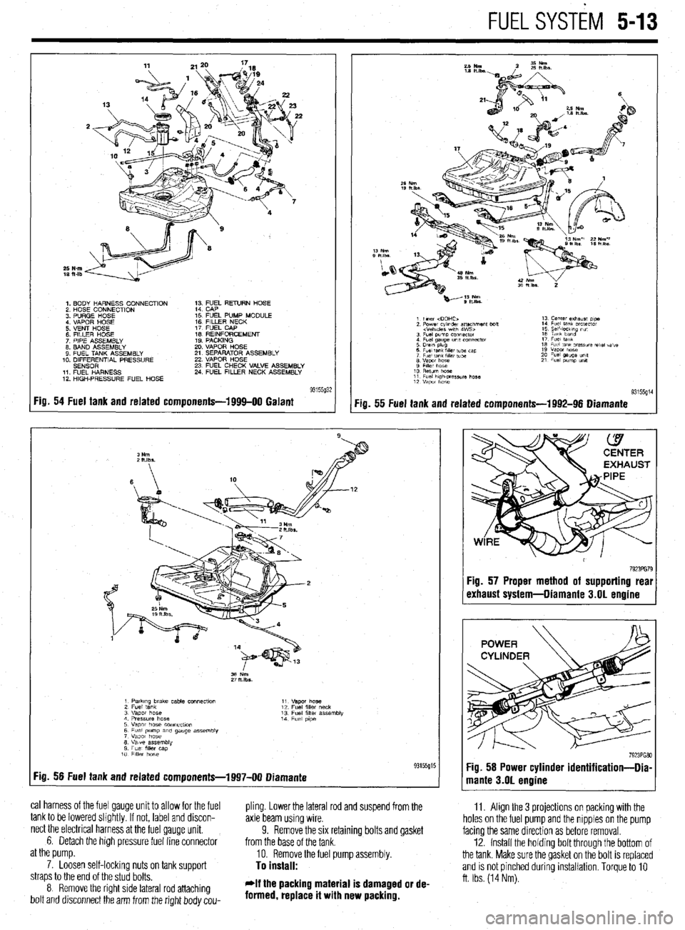
FUELSYSTiM 5-13
1. BODY HARNESS CONNECTION
2 HOSE CONNECTION
3 PURGE HOSE
4 VAPOR HOSE
5 VENT HOSE
6 FllLER HOSE
7 PIPE ASSEMBLY
8. BAND ASSEMBLY
9 FUEL TANK ASSEMBLY
10. DIFFERENTIAL PRESSURE
SENSOR
11 FUEL HARNESS
12 HIGH-PRESSURE FUEL HOSE 1; ;;JL RETURN HOSE
15 FUEL PUMP MODULE
16 FILLER NECK
17 FUEL CAP
IS REINFORCEMENT
19 PACKING
20 VAPOR HOSE
21 SEPARATOR ASSEMBLY
22 VAPOR HOSE
23 FUEL CHECK VALVE ASSEMBLY
24 FUEL FILLER NECK ASSEMBLY
Fig. 54 Fuel tank and related components-1999-00 Galant
:ia. 55 Fuel tank and related components-1992-96 Diamante
11. Align the 3 projections on packing with the
holes on the fuel pump and the nipples on the pump
facing the same direction as before removal.
12. Install the holdrng bolt through the bottom of
the tank. Make sure the gasket on the bolt is replaced
and is not pinched during installation. Torque to 10
ft. Ibs. (14 Nm).
1 PatkIng brake cable COnneCtlo” 11
2 Fuel tank “.qm hose
12 Fuel fllk, neck
3 “apot hose 13 Fuel filler assembly
4 Pressure hose 14
5 Vapor hose COnneCflOn Fuel p,pe
6 Fuel pump am gauge assembly
7 Vapor hose
8 Valve assembly
9 Fuel mer cap
10 FllkY hose
:ig. 56 Fuel tank and related components-1997-00 Diamante 93155g15
cal harness of the fuel gauge unit to allow for the fuel
pling. Lower the lateral rod and suspend from the
tank to be lowered slightly. If not, label and discon-
axle beam using wire.
nect the electrical harness at the fuel gauge unit.
6. Detach the high pressure fuel line connector 9. Remove the six retaining bolts and gasket
from the base of the tank.
at the pump.
10. Remove the fuel pump assembly.
7. Loosen self-lockinq nuts on tank suooort
To install: straps to the end of the stud bolts.
8 Remove the right side lateral rod attaching
bolt and drsconnect the arm from the right body cou- *If the packing material is damaged or de-
formed, replace it with new packing.
7923PG79 :ig. 57 Proper method of supporting real
rxhaust system-Diamante 3.01 engine
Page 213 of 408
640 CHASSIS ELECTRICAL
careful not to allow anything to come in contact with
the air bag unit.
16. Remove the glove box lamp assembly.
17. Remove the remaining instrument panel
mounting screws and remove the instrument panel
from the vehicle.
18. Remove the left side foot shower ductwork,
lap cooler duct and center duct.
19. Remove the front and center reinforcements
and center stay assembly.
20. Remove the air distribution duct assembly.
21. Detach all connectors from heater-box-
mounted items.
22. Remove the heater box mounting screws and
nut, then remove the unit from the vehicle.
23. Disassemble on a workbench. Remove the
heater core from the heater case.
To install:
24. Thoroughly clean and dry the inside of the
case and install the heater core and all related parts.
25. Install the heater unit to the vehicle and install
the mounting screws and nut. Be sure the evaporator
case and heater case are fitted together properly. At-
tach all connectors to heater-box-mounted items.
26. Install the air distribution duct assembly. In-
stall the front and center reinforcements and center
stay assembly.
27. Install the center duct, lap cooler duct and left
side foot shower duct.
28. Install the instrument panel and mounting
screws.
29. Install the glove box lamp assembly.
30. Secure the steering column and attach all
steering column connectors.
31. Install the speedometer cable adapter to the
instrument panel.
32. Install the instrument cluster and the instru-
ment cluster bezel.
33. Install the speakers to the top of the instru-
ment panel.
34. Install the cup holder.
35. Install the climate control system control
head.
36. Install the stereo entertainment system and
bezel.
37. Install the screw below the glove box assem-
bly, and the entire glove box unit.
38. Install the steering column covers.
39. Install the knee protector support bracket, the
protector and the decorative plugs.
40. Install the console and the ashtray. 41. Install the right side foot shower duct.
42. Install the passenger side undercover.
43. Connect the heater hoses to the core tubes.
44. Fill the cooling system.
45. Connect the negative battery cable and check
the entire climate control system for proper operation
and leaks.
Galant
# See Figures 26, 27, and 28
1. Disconnect the negative battery cable.
2. Disarm the air bag. Refer to the procedure
earlier in this section.
3. With the engine cold, set the temperature
control lever to the FULL HOT position. Drain the en-
gine coolant.
4. Disconnect the coolant hoses running to the
heater pipes at the firewall.
5. Remove the center console.
6. Remove the heater cover.
7. Remove the steering wheel.
8. Remove the small steering column panel.
9. Remove the undercover.
10. Remove the upper and lower steering column
covers and detach the wiring connectors.
11. Remove the instrument cluster hood.
12. Remove the mounting screws for the instru-
ment cluster.
13. Pull the cluster out and disconnect the
speedometer adapter behind the cluster. Remove the
cluster.
14. Remove the floor console and the under-
frame.
15. Disconnect and remove the air duct, lap
heater duct, side defroster duct and the vertical de-
froster duct.
16. Remove the glove box.
17. Remove the ashtray and its mount. Discon-
nect the light wiring before removing.
18. Remove the heater control faceplate.
19. Remove the heater control panel and discon-
nect its harness.
20. Remove the right side undercover from the
instrument panel and remove the underframe.
21. On the left side of the instrument panel, re-
move the fuse box cover and unbolt the fusebox from
the instrument panel.
22. Remove the front pillar (windshield pillar
trim) from each pillar.
23. Remove the kick panel trim from each side.
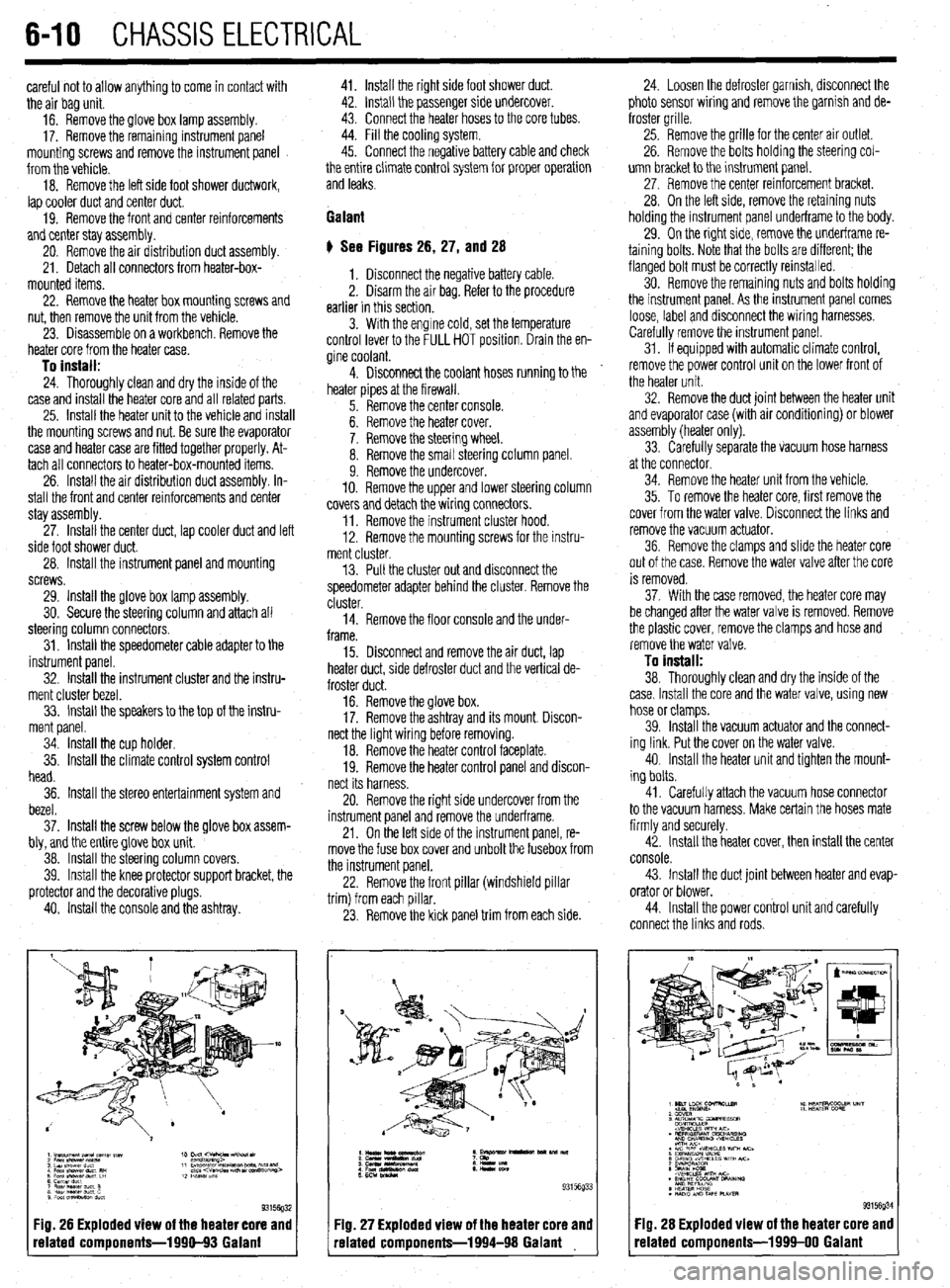
Fig. 26 Exploded view of the heater core and
related components-1990-93 Galant
:IQ. 27 Exploded view of the heater core and
-elated components-1994-98 Galant 24. Loosen the defroster garnish, disconnect the
photo sensor wiring and remove the garnish and de-
froster grille.
25. Remove the grille for the center air outlet.
26. Remove the bolts holding the steering col-
umn bracket to the instrument panel.
27, Remove the center reinforcement bracket.
28. On the left side, remove the retaining nuts
holding the instrument panel underframe to the body.
29. On the right side, remove the underframe re-
taining bolts. Note that the bolts are different; the
flanged bolt must be correctly reinstalled.
30. Remove the remaining nuts and bolts holding
the instrument panel. As the instrument panel comes
loose, label and disconnect the wiring harnesses.
Carefully remove the instrument panel.
31. If equipped with automatic climate control,
remove the power control unit on the lower front of
the heater unit.
32. Remove the duct joint between the heater unit
and evaporator case (with air conditioning) or blower
assembly (heater only).
33. Carefully separate the vacuum hose harness
at the connector.
34. Remove the heater unit from the vehicle.
35. To remove the heater core, first remove the
cover from the water valve. Disconnect the links and
remove the vacuum actuator.
36. Remove the clamps and slide the heater core
out of the case. Remove the water valve after the core
is removed.
37. With the case removed, the heater core may
be changed after the water valve is removed. Remove
the plastic cover, remove the clamps and hose and
remove the water valve.
To install:
38. Thoroughly clean and dry the inside of the
case. Install the core and the water valve, using new
hose or clamps.
39. Install the vacuum actuator and the connect-
ing link. Put the cover on the water valve.
40. Install the heater unit and tighten the mount-
ing bolts.
41. Carefully attach the vacuum hose connector
to the vacuum harness. Make certain the hoses mate
firmly and securely.
42. Install the heater cover, then install the center
console.
43. Install the duct joint between heater and evap-
orator or blower.
44. Install the power control unit and carefully
connect the links and rods.
Fig. 28 Exploded view of the heater core and
related components-1999-00 Galant
Page 239 of 408
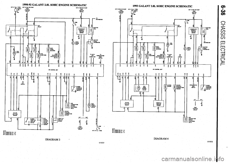
1990-92 GALANT 2.OL SOHC ENGINE SCHEMATIC
1993 GALANT 2.OL SOHC ENGINE SCHEMATIC HOT IN RIB aR START
STEki
CIRCUT HOTINRWORSTART
FROH
16NlTlON
SWITCH
t HOT IN RUR OR STlRT
HOT AT ALL TIMES
HOT IN RU4 DR START
FRDtl
IGNITION
SWITCH
I EEE LIGHT
! a
s ;
--
T m
> CHECK
EN6lNE
LIGHT
%
i E IGNITION
PDWER
4 ’
TRANSISTOR
D
4
&Rl,DR
s
ICNlTlOK
FUWER
TRARSlSTOR
m
TO OATA
LINK SPEED&TEfl/
CONRECTM
REED
( !iWlTCH TO
UC
WI CWJTROL UNIT
IDLE
> SFEED
CONTROL
MOTOR AIT
! n/T.
I 1 0
1
STEK
ClRCUT EGR
TEnFERA~
SENSOR
mLIFoRRlA
WLn
VOLUME
AIR FLOW
SENSOR
I
5
E
! %
FUSE *
I7
IOA
HOT AT ALL TIMES EGR
TEMFERATLRE
SERSDR
, (~~IFORR~A
ONLV) An L MT
.
B m
11
STARTING
CIRCUT NOTE
I’IFI CORRECTOR Cl0 = -A-
WI coRNEcmR CII - 3’
“FI CONNECTOR Cl2 I 77
DIAGRAM 4 93156E02
NOlE
MFI CCMECTOR Cl0 = ‘A-
WI CONNECTOR Cl, = %’
WI CDNNECTOR Cl2 = C
DIAGRAM3 l 93156EOl
Page 241 of 408
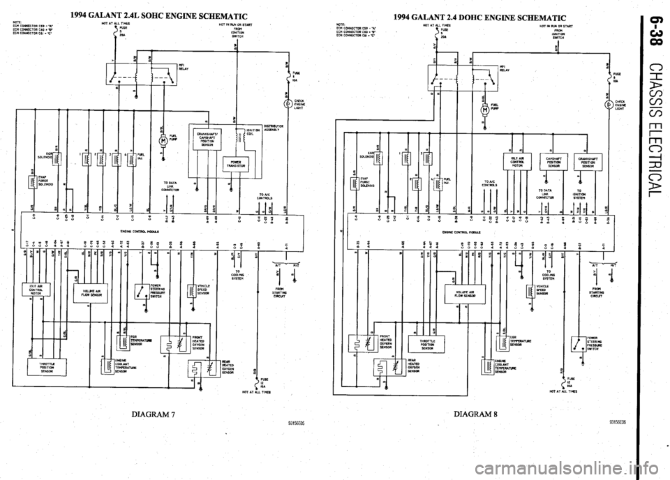
1994 GALANT 2.4L SOHC ENGINE SCHEMATIC
1994 GALANT 2.4 DOHC ENGINE SCHEMATIC NOTE
ECM CONNECTOR CS9 = ‘A’
ECH CONNECTOR C60 = B
ECH CONNECTOR Cti, = -I’ NOTE
ECH CONNECTOR C59 = ‘A-
ECH CONNECTOR C60 = ‘B
ECH CONNECTOR CM = -17 HOT AT ALL Tl?lES
FUSE
s
20A
s HQt IN RUN OR START
FRQ+l
IGNITION
SWITCH *
ON
:li IGI
SI
FVSE
0
IOA
> CHECK
ENGINE
LIGHT CHECU
/ ENOM
LIGHT
-T-T FUEL Pup
TO DATA
LINU
CONNECTOR I
CRANKSHAFT/
CAMSHAFT
POSITION
SENSOR
PQW2R
TRANSISTOR
m
(D
A
a
=
TO AK
CONTROLS
ENGINE CONTROL WCCU.2
m FRONT
H2AT2D
OXYGEN
SENSOR TO
CDDLING
SYSTEM
VEHICLE
SPEED
SENSOR
f FROM
START1116
CIRCWT
EGR
TEllPERATuRE
SENSOR
93156E05
HOT AT !NSlNE
3OLANT
rEMPERATu3E
ENSOR REAR
HEATED
OXYGEN
SENSOR REAR
HUTED
OXYGEN
SENSOA
TIM!3 vJ* HOT AT ALL TlblES
DIAGRAM 7
. DIAGRAM 8