1900 MITSUBISHI DIAMANTE fuel cap
[x] Cancel search: fuel capPage 154 of 408
DRIVEABILITYAND EMISSIONS CONTROLi 4-11
fold. Resistance changes in response to the ambient
air temperature. The sensor has a negative tempera-
ture coefficient. As the temperature of the sensor
rises the resistance across the sensor decreases. Thil
provides a signal to the PCM indicating the tempera-
ture of the incoming air charge. This sensor helps the
PCM to determine spark timing and air/fuel ratio. In-
formation from this sensor is added to the pressure
sensor information to calculate the air mass being
sent to the cylinders. The IAT receives a 5-volt refer-
ence signal and the signal return is based upon the
change in the measured resistance due to tempera-
ture.
TESTING
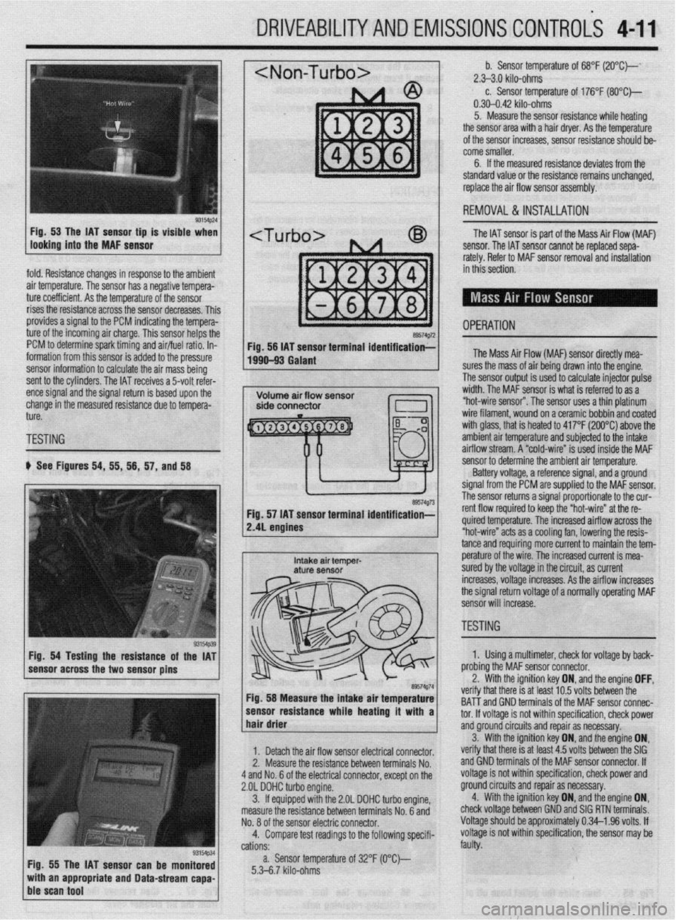
b See Figures 54, 55, 56, 57, and 58
Fig. 54 Testing the resistance of the IAT
sensor across the two sensor pins
Fig. 55 The IAT sensor can be monitored
with an appropriate and Data-stream capa-
ble scan tool
~1 b. Sensor temperature of 68°F (2O”C)--‘ 2.>3.0 kilo-ohms c. Sensor temperature of 176°F (SO*C)-
0.30-0.42 kilo-ohms
5. Measure the sensor resistance while heating
the sensor area with a hair dryer. As the temperature
of the sensor increases, sensor resistance should be-
come smaller.
6. If the measured resistance deviates from the
standard value or the resistance remains unchanged,
replace the air flow sensor assembly.
1 REMOVAL&INSTALLATION
The IAT sensor is part of the Mass Air Flow (MAF)
sensor. The IAT sensor cannot be replaced sepa-
rately. Refer to MAF sensor removal and installation
in this section.
- OPERATION a9574g72 Fig. 56 IAT sensor terminal identification;-
1990-93 Galant The Mass Air Flow (MAF) sensor directly mea-
lres the mass of air being drawn into the engine.
I ?he sensor output is used to calculate injector pulse
width. The MAF sensor is what is referred to as a
“hot-wire sensor”. The sensor uses a thin platinum
wire filament, wound on a ceramic bobbin and coated
with glass, that is heated to 417°F (200°C) above the
amh+en+ nir +PmnPrfijre and subiected to the intake
..I._ ~ ..-.. .“..‘r-,u.. ai mow stream. A “cold-wire” is used inside the MAF
sensor resuirance wnoe nearmg ir wnn a 1
hair drier ‘hat melt: IS al I~“< ,“.., lvllQ UtiLnbtill ,,,=
tnd GND terminals of the MAF sensor connec-
tor. If voltaae is not within specification, check power
1. Detach the air flow sensor electrical connector.
2. Measure the resistance between terminals No.
4 and No. 6 of the electrical connector, except on the
2.OL DOHC turbo engine.
3. ff equipped with the 2.OL DOHC turbo engine,
measure the resistance between terminals No. 6 and
No. 8 of the sensor electric connector.
4. Compare test readings to the following specifi-
cations:
a. Sensor temperature of 32°F (O“C)--
5.3-6.7 kilo-ohms and groundcircuits and repair as necessary.
verify that there is at least 4.5 volts between the SIG 3. With the ignition key ON, and,the engine ON,
and GND terminals of the MAF sensor connector. If
voltage is not within specification, check power and
ground circuits and repair as necessary.
4. With the ignition key ON, and the engine ON,
check voltage between GND and SIG RTN terminals.
Voltage should be approximately 0.34-l .96 volts. If
voltage is not within specification, the sensor may be
faulty.
/ sensor to determine the ambient air temperature.
Battery voltage, a reference signal, and a ground
signal from the PCM are supplied to the MAF sensor.
rho ~pn**r rp+++rns a signal proportionate to the cur-
re. The increased airflow across the
s a cooling fan, lowering the resis-
mo more current to maintain the tem- tance and requir
e^-‘.._^ ^I LL^
I
Intake air temper- pe~a+ure UI me wire. The increased current is mea- aturf sensor sured by the voltage in the circuit, as current
increases, voltage increases. As the airflow increases
the signal return voltage of a normally operating MAF
sensor will increase.
, ~~1 TESTING - II ire” at the re-
89574g74 Fig. 58 Measure the intake air temperature
-----_ ---1-a---- L..- L--1. . . .*a 1. Using a multimeter, check for voltage by back-
nrr\hinn +hn MAF sensor connector.
the ignition key ON, and the engine OFF, .^-^ :- -’ ‘.txt In E; \mltr hahrman tha veriry t
BAT-T i
Page 170 of 408
DRIVEABILITYAND EMISSIONS CONTROLS 4-27
WITHOUTASCANTOOL
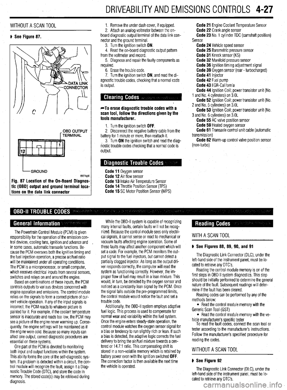
8 See Figure 87. 1. Remove the under dash cover, if equipped.
2. Attach an analoa voltmeter between the on-
board diagnostic outpit terminal of the data link con-
nector and the ground terminal
3. Turn the ignition switch ON.
4. Read the on-board diagnostic output pattern
from the voltmeter and record.
5. Diagnose and repair the faulty components as
required.
OBD OUTPUT
[TERMINAL
tic (OBO) output and ground terminal loca-
tions on the data link connector
6. Erase the trouble code.
7. Turn the ignition swatch ON, and read the di-
agnostic trouble codes, checking that a normal code
is output.
*To erase diagnostic trouble codes with a
scan tool, follow the directions given by the
tools manufacturer.
1. Turn the ignition switch OFF. 2. Disconnect the negative battery cable from the
battery for 1 minute or more, then reattach it.
3. Turn ON the ignition switch and read the diag-
nostic trouble codes checking that a normal code is
output.
Code 11 Oxygen sensor Code 12 Air flow sensor Code 13 Intake Air Temperature Sensor Code 14 Throttle Position Sensor (TPS) Code 15 SC Motor Position Sensor (MPS)
Code 21 Engine Coolant Temperature Sensor Code 22 Crank angle sensor Code 23 No. 1 cylinder TDC (camshaft position)
Sensor
Code 24 Vehicle speed sensor Code 25 Barometric pressure sensor Code 31 Knock sensor (KS) Code 32 Manifold pressure sensor Code 36 Ignition timmg adjustment signal Code 39 Oxygen sensor (rear - turbocharged) Code 41 Injector Code 42 Fuel pump Code 43 EGR-California Code 44 Ignition Coil; power transistor unit (No.
1 and No. 4 cvlinders) on 3.OL
Code 62 ignition Coil; power transistor unit (No.
2 and No. 5 cvlinders) on 3.OL
Code 53 ignition Coil; power transistor unit (No.
3 and No. 6 cylinders) on 3.OL
Code 55 AC valve position sensor Code 59 Heated oxygen sensor Code 61 Transaxle control unit cable (automatic
transmission)
Code 62 Warm-up control valve position sensor
(non-turbo)
The Powertrain Control Module (PCM) is given
responsibrlity for the operation of the emission con-
trol devices, cooling fans, ignition and advance and
in some cases, automatic transaxle functions. Be-
cause the PCM oversees both the ignition timing and
the fuel injection operation, a precise air/fuel ratio
will be maintained under all operating conditions,
The PCM is a microprocessor, or small computer,
which receives electrical inputs from several sensors,
switches and relays on and around the engine.
Based on combinations of these inputs, the PCM
controls outputs to various devices concerned with
engine operation and emissions. The control module
relies on the signals to form a correct picture of cur-
rent vehicle operation. If any of the input signals is
incorrect, the PCM reacts to whatever picture is
painted for it. For example, if the coolant temperature
sensor is inaccurate and reads too low, the PCM may
see a picture of the engine never warming up. Conse-
quently, the engine settings will be maintained as if
the engine were cold. Because so many inputs can
affect one output, correct diagnostic procedures are
essential on these systems,
One part of the PCM is devoted to monitoring
both input and output functions within the system.
This ability forms the core of the self-diagnostic sys-
tem. If a problem is detected within a circuit, the con-
trol module will recognize the fault, assign it a Diag-
nostic Trouble Code (DTC), and store the code in
memory. The stored code(s) may be retrieved during
diagnosis. While the OBD-II system is capable of recognizing
many internal faults, certain faults WIII not be recog-
nized. Because the control module sees only electri-
cal signals, it cannot sense or react to mechanical or
vacuum faults affecting engine operation. Some of
these faults may affect another component which will
set a code. For example, the PCM monitors the out-
put signal to the fuel injectors, but cannot detect a
partially clogged injector. As long as the output dri-
ver responds correctly, the computer will read the
system as functioning correctly. However, the im-
proper flow of fuel may result in a lean mixture. This
would, in turn, be detected by the oxygen sensor and
noticed as a constantly lean signal by the PCM. Once
the signal falls outside the pre-programmed limits,
the control module would notice the fault and set a
trouble code.
Additionally, the OBD-II system employs adaptive
fuel logic. This process is used to compensate for
normal wear and variability within the fuel system.
Once the engine enters steady-state operation, the
control module watches the oxygen sensor signal for
a bias or tendency to run slightly rich or lean. If such
a bias is detected, the adaptive logic corrects the fuel
delivery to bring the air/fuel mixture towards a cen-
tered or 14.7:1 ratio. This compensating shift is
stored In a non-volatile memory which is retained by
battery power even with the ignition switched
OFF. The correction factor is then available the next time
the vehicle is operated.
WITHASCANTOOL
8 See Figures 88, 89, 90, and 91
The Diagnostic Link Connector (DLC), under the
left-hand side of the instrument panel, must be lo-
cated to retrieve any OTC’s
Reading the control module memory is on of the
first steps in OBD II system diagnostics. This step
should be initially performed to determine the general
nature of the fault. Subsequent readings will deter-
mine if the fault has been cleared.
Reading codes can be performed by any of the
methods below:
l Read the control module memory with the
Generic Scan Tool (GST)
l Read the control module memory with the ve-
hicle manufacturers specific tester
To read the fault codes, connect the scan tool or
tester according to the manufacturers instructions.
Follow the manufacturers specified procedure for
reading the codes.
WITHOUTASCANTOOL
8 See Figure 92
The Diagnostic Link Connector (DLC), under the
left-hand side of the instrument panel, must be lo-
cated to retrieve any DTC’s.
Page 190 of 408
FUELSYSTEM 513
l Always replace worn fuel fitting O-rings with
new. Do not substitute fuel hose or equivalent, where
I
The Multi-Point Injection (MPI) system is electroni-
rally controlled by the Engine Control Module (ECM),
based on data from various sensors. The ECM controls
the fuel flow, idle speed and ignition timing. fuel pipe is installed.
Fuel is supplied to the injectors by an electric in-
tank fuel pump and is distributed to the respective in-
jectors via the main fuel pipe. The fuel pressure ap-
plied to the injector is constant and higher than the
pressure in the intake manifold. The pressure is con-
trolled by the fuel pressure regulator. The excess fuel
is returned to the fuel tank through the fuel return pipe.
When an electric current flows in the injector, the
injector valve is fully opened to supply fuel. Since the
fuel pressure is constant, the amount of the fuel in-
jetted from the injector into the manifold is increased
or decreased in proportion to the time the electric
current flows. Based on ECU signals, the injectors in-
ject fuel to the cylinder manifold ports in firing order. Fuel injection systems remain under pres-
sure after the engine has been turned OFF.
Properly relieve fuel pressure before discon-
neeting any fuel lines. Failure to do so may
result in fire or personal injury.
1. Turn the ignition to the OFF position.
2. Loosen the fuel filler cap to release fuel tank
pressure.
I
The flow rate of the air drawn through the air
cleaner is measured by the air flow sensor. The air
enters the air intake plenum or manifold through the
throttle body. In the intake manifold, the air is mixed
with the fuel from the injectors and is drawn into the
cylinder, The air flow rate is controlled according to
the degree of the throttle valve and the servo motor
openings. The system is monitored through a num-
ber of sensors which feed information on engine con-
ditions and requirements to the ECM. The ECM cal-
culates the injection time and rate according to the
signals from the sensors,
Safety is the most important factor when perform-
ing not only fuel system maintenance but any type of
maintenance. Failure to conduct maintenance and re-
pairs in a safe manner may result in serious personal
injury or death. Maintenance and testing of the vehi-
cle’s fuel system components can be accomplished
safely and effectively by adhering to the following
rules and guidelines.
l To avoid the possibility of fire and personal in-
jury, always disconnect the negative battery cable un-
less the repair or test procedure requires that battery
voltage be applied.
l Always relieve the fuel system pressure prior to
disconnecting any fuel system component (injector,
fuel rail, pressure regulator, etc.), fitting or fuel line
connection. Exercise extreme caution whenever re- Observe all applicable safety precautions
when working around fuel. Whenever servic-
ing the fuel system, always work in a well
ventilated area. Do not allow fuel spray or va-
pors to come in contact with a spark or open
flame. Keep a dry chemical fire extinguisher
near the work area. Always keep fuel in a con-
tainer specifically designed for fuel storage;
also, always properly seal fuel containers to
avoid the possibility of fire or explosion.
3. For the Mirage, Diamante, and 1994-00
Galant, remove the rear seat cushion, then remove
the service cover and detach the fuel pump harness
connector.
4. For the 1990-93 FWD Galant, detach the fuel
pump harness connector located in the area of the
fuel tank. It may be necessary to raise the vehicle to
access the connector.
5. For the 1990-93 AWD Galant, remove the car-
pet from the trunk, locate the fuel tank wiring at the
pump access cover, then detach the wiring.
6. Start the vehicle and allow it to run until it
stalls from lack of fuel. Turn the key to the OFF posi-
tion.
7. Disconnect the negative battery cable, then at-
tach the fuel pump connector. Install the access .
cover, cushion or carpet as necessary.
8. Wrap shop towels around the fitting that is be-
ing disconnected to absorb residual fuel in the lines.
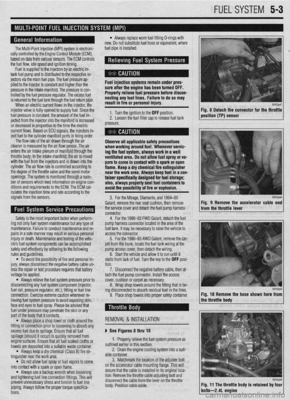
9. Place shop towels into proper safety container. Fig, 8 Detach the connector for the throttle
position (TP) sensor
93153ps5 Fig, 9 Remove the accelerator cable end
from the throttle lever
Fig. IO Remove the hose shown here from
lieving fuel system pressure to avoid exposing skin,
face and eyes to fuel spray. Please be advised that
fuel under pressure may penetrate the skin or any
part of the body that it contacts.
l Always place a shop towel or cloth around the
fitting or connection prior to loosening to absorb any
excess fuel due to spillage. Ensure that all fuel
spillage (should it occur) is quickly removed from
enginesurfaces. Ensure that all fuel soaked cloths or
towels are deposited into a suitable waste container.
l Always keep a dry chemical (Class B) fire ex-
tinguisher near the work area.
l Do not allow fuel spray or fuel vapors to come
into contact with a spark or open flame.
l Always use a backup wrench when loosening’
and tightening fuel line connection fittings. This will
prevent unnecessary stress and torsion to fuel line
piping. Always follow the proper torque specifica-
tions. REMOVAL &INSTALLATION
p See Figures 8 thru 18
1. Properly relieve the fuel system pressure as
outlined earlier in this section.
2. Drain the engine cooling system into a suit-
able container.
3. Matchmark the jocation of the adjuster bolt
on the accelerator cable mounting flange. This will
assure that the cable is installed in its original loca-
tion. Remove the throttle cable adjusting bolt and
disconnect the cable from the lever on the throttle
body. Position cable aside.
Page 200 of 408
FUELSYSTiM 5-13
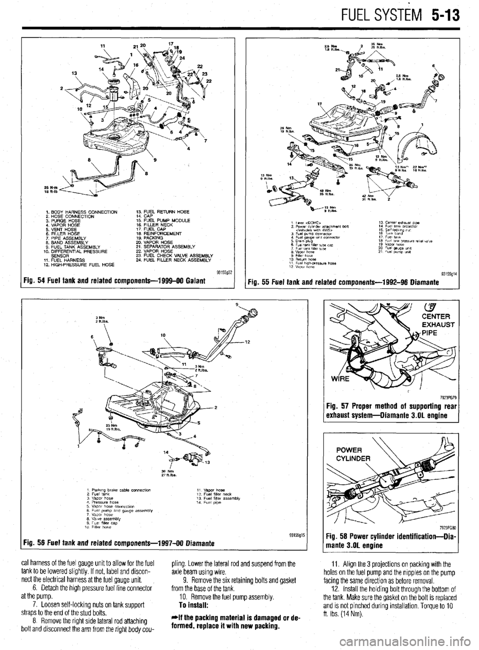
1. BODY HARNESS CONNECTION
2 HOSE CONNECTION
3 PURGE HOSE
4 VAPOR HOSE
5 VENT HOSE
6 FllLER HOSE
7 PIPE ASSEMBLY
8. BAND ASSEMBLY
9 FUEL TANK ASSEMBLY
10. DIFFERENTIAL PRESSURE
SENSOR
11 FUEL HARNESS
12 HIGH-PRESSURE FUEL HOSE 1; ;;JL RETURN HOSE
15 FUEL PUMP MODULE
16 FILLER NECK
17 FUEL CAP
IS REINFORCEMENT
19 PACKING
20 VAPOR HOSE
21 SEPARATOR ASSEMBLY
22 VAPOR HOSE
23 FUEL CHECK VALVE ASSEMBLY
24 FUEL FILLER NECK ASSEMBLY
Fig. 54 Fuel tank and related components-1999-00 Galant
:ia. 55 Fuel tank and related components-1992-96 Diamante
11. Align the 3 projections on packing with the
holes on the fuel pump and the nipples on the pump
facing the same direction as before removal.
12. Install the holdrng bolt through the bottom of
the tank. Make sure the gasket on the bolt is replaced
and is not pinched during installation. Torque to 10
ft. Ibs. (14 Nm).
1 PatkIng brake cable COnneCtlo” 11
2 Fuel tank “.qm hose
12 Fuel fllk, neck
3 “apot hose 13 Fuel filler assembly
4 Pressure hose 14
5 Vapor hose COnneCflOn Fuel p,pe
6 Fuel pump am gauge assembly
7 Vapor hose
8 Valve assembly
9 Fuel mer cap
10 FllkY hose
:ig. 56 Fuel tank and related components-1997-00 Diamante 93155g15
cal harness of the fuel gauge unit to allow for the fuel
pling. Lower the lateral rod and suspend from the
tank to be lowered slightly. If not, label and discon-
axle beam using wire.
nect the electrical harness at the fuel gauge unit.
6. Detach the high pressure fuel line connector 9. Remove the six retaining bolts and gasket
from the base of the tank.
at the pump.
10. Remove the fuel pump assembly.
7. Loosen self-lockinq nuts on tank suooort
To install: straps to the end of the stud bolts.
8 Remove the right side lateral rod attaching
bolt and drsconnect the arm from the right body cou- *If the packing material is damaged or de-
formed, replace it with new packing.
7923PG79 :ig. 57 Proper method of supporting real
rxhaust system-Diamante 3.01 engine
Page 203 of 408
.
5-16 FUELSYSTEM
6. Disconnect the return hose and the high
pressure fuel hose.
7. Using special tool MB991480 or equivalent,
remove the fuel pump retaining cap and remove the
pump assembly.
Observe all applicable safety precautions
when working around fuel. Whenever servic-
ing the fuel system, always work in a well
ventilated area. Do not allow fuel spray or
vapors to come in contact with a spark or
open flame. Keep a dry chemical fire extin-
guisher near the work area. Always keep fuel
in a container specifically designed for fuel
storage; also, always properly seal fuel con-
tainers to avoid the possibility of fire or ex-
plosion.
To install:
*If the packing material is damaged or de-
formed, replace it with new packing.
8. Install the packing to the fuel tank.
9. Install the fuel pump assembly to the tank
and align the mating marks on the pump and the
floorpan.
10. Tighten the fuel pump retaining cap using
tool MB991480 or equrvalent.
11. Connect the high pressure hose, return hose
and the fuel tank wirmg.
12. Connect the negative battery cable.
13. Check the fuel pump for proper pressure and
inspect the entire system for leaks.
14. Apply sealant to the access cover and install
the cover.
15. Install the rear seat cushion.
TESTING
1. Relieve fuel system pressure.
2. Disconnect the battery negative cable.
3. Disconnect the fuel hrgh pressure hose at the
delivery pipe side.
Observe all applicable safety precautions
when working around fuel. Whenever servic-
ing the fuel system, always work in a well
ventilated area. Do not allow fuel spray or
vapors to come in contact with a spark or
open flame. Keep a dry chemical fire extin-
guisher near the work area. Always keep fuel
in a container specifically designed for fuel
storage; also, always properly seal fuel con-
tainers to avoid the possibility of fire or ex-
alosion.
4. Connect a fuel pressure gauge to tools
MD998709 and MD998742 or exact equivalent, with
appropriate adapters, seals and/or gaskets to prevent
leaks during the test. Install the gauge and adapter
between the delivery pipe and high pressure hose. In-
stall carefully to prevent leaks.
5. Connect the negative battery cable.
6. Apply battery voltage to the terminal for fuel
pump activation (located in the engine compartment)
to run the fuel pump, and check for leaks.
7. Start the engine and run at curb idle speed.
8. Measure the fuel pressure and compare to
the specifications listed in the chart in Section 1.
9. Locate and disconnect the vacuum hose run-
ning to the fuel pressure regulator. Plug the end of
the hose and record the fuel pressure again. The fuel
pressure should have increased approximately IO
psi. 10. Reconnect the vacuum hose the fuel pressure
regulator. After the fuel pressure stabilizes, race the
engine 2-3 times and check that the fuel pressure
does not fall when the engine is running at idle.
il. Check to be sure there is fuel pressure in the
return hose by gently pressing the fuel return hose
with fingers while racing the engine. There will be no
fuel pressure in the return hose when the volume of
fuel flow is low.
12. If fuel pressure is too low, check for a
clogged fuel filter, a defective fuel pressure regulator
or a defective fuel pump, any of which will require re-
placement.
13. If fuel pressure is too high, the fuel pressure
regulator is defective and will have to be replaced or
the fuel return is bent or clogged. If the fuel pressure
readmg does not change when the vacuum hose is
disconnected, the hose is clogged or the valve is
stuck in the fuel pressure regulator and it will have to
be replaced.
14. Stop the engine and check for changes in the
fuel pressure gauge. It should not drop. If the gauge
reading does drop, watch the rate of drop. If fuel
pressure drops slowly, the likely cause is a leaking
injector which will require replacement. If the fuel
pressure drops immediately after the engine is
stopped, the check valve in the fuel pump isn’t clos-
ing and the fuel pump will have to be replaced.
15. Relieve fuel system pressure.
16. Disconnect the high pressure hose and re-
move the fuel pressure gauge from the delivery pipe.
17. Install a new O-ring in the groove of the high
pressure hose. Connect the hose to the delivery pipe
and tighten the screws. After Installation, apply bat-
tery voltage to the terminal for fuel pump activation to
run the fuel pump. Check for leaks.
Page 389 of 408
TROUBLESHOOiNG 11-7
4. Starter motor spins, but does not engage
a. Check the starter motor for a seized or binding pinion gear.
b. Remove the flywheel inspection plate and check for a damaged ring gear.
Gasoline Engines
1. Engine runs poor/y, hesiiates
a. Check the engine ignition system operation and adjust if possible, or replace defective
parts.
b. Check for restricted fuel injectors and replace as necessary.
c. Check the fuel pump output and delivery. Inspect fuel lines for restrictions. If the fuel
pump pressure is below specification, replace the fuel pump.
d. Check the operation of the engine management system and repair as necessary.
2. Enfline lacks power
a. Check the engine’s tune-up status. Note the tune-up specifications and check for items
such as severely worn spark plugs; adjust or replace as needed. On vehicles with
manually adjusted valve clearances, check for tight valves and adjust to specification.
b. Check the air filter and air intake system. Replace the air filter if it is dirty or contami-
nated. Check the fresh air intake system for restrictions or blockage.
c. Check the operation of the engine fuel and ignition management systems. Check the
sensor operation and wiring. Check for low fuel pump pressure and repair or replace
components as necessary.
d. Check the throttle linkage adjustments. Check to make sure the linkage is fully open-
ing the throttle. Replace any worn or defective bushings or linkages.
e. Check for a restricted exhaust system. Check for bent or crimped exhaust pipes, or in-
ternally restricted mufflers or catalytic converters. Compare inlet and outlet tempera-
tures for the converter or muffler. If the inlet is hot, but outlet cold, the component is
restricted.
f. Check for a loose or defective knock sensor. A loose, improperly torqued or defective
knock sensor will decrease spark advance and reduce power. Replace defective knock
sensors and install using the recommended torque specification.
g. Check for engine mechanical conditions such as low compression, worn piston rings,
worn valves, worn camshafts and related parts. An engine which has severe mechani-
cal wear, or has suffered internal mechanical damage must be rebuilt or replaced to re-
store lost power.
h. Check the engine oil level for being overfilled. Adjust the engine’s oil level, or change
the engine oil and filter, and top off to the correct level.
i. Check for an intake manifold or vacuum hose leak. Replace leaking gaskets or worn
vacuum hoses.
j. Check for dragging brakes and replace or repair as necessary.
k. Check tire air pressure and tire wear. Adjust the pressure to the recommended set-
tings. Check the tire wear for possible alignment problems causing increased rolling
resistance, decreased acceleration and increased fuel usage.
I. Check the octane rating of the fuel used during refilling, and use a higher octane rated
fuel.
3. Poor fuel economy
a. Inspect the air filter and check for any air restrictions going into the air filter housing.
Replace the air filter if it is dirty or contaminated.
b. Check the engine for tune-up and related adjustments. Replace worn ignition parts,
check the engine ignition timing and fuel mixture, and set to specifications if possible.
c. Check the tire size, tire wear, alignment and tire pressure. Large tires create more
rolling resistance, smaller tires require more engine speed to maintain a vehicle’s road
speed. Excessive tire wear can be caused by incorrect tire pressure, incorrect wheel
alignment or a suspension problem. All of these conditions create increased rolling
resistance, causing the engine to work harder to accelerate and maintain a vehicle’s
speed.
d. Inspect the brakes for binding or excessive drag. A sticking brake caliper, overly ad-
justed brake shoe, broken brake shoe return spring, or binding parking brake cable or
linkage can create a significant drag, brake wear and loss of fuel economy. Check the
brake system operation and repair as necessary.
4. Engine runs on (diesels) when turned off
a. Check for idle speed set too high and readjust to specification.
b. Check the operation of the idle control valve, and replace if defective.
c. Check the ignition timing and adjust to recommended settings.
Check for defective
sensors or related components and replace if defective.
d. Check for a vacuum leak at the intake manifold or vacuum hose
and replace defective
gaskets or hoses.
e. Check the engine for excessive carbon build-up in the combustion chamber. Use a
recommended decarbonizing fuel additive or disassemble the cylinder head to remove
the carbon.
f. Check the operation of the engine fuel management system and replace defective sen-
sors or control units.
g. Check the engine operating temperature for overheating and repair as necessary. 5. Engine knocks and pinfls during heavy accele/ation, and on steep hills
a. Check the octane rating of the fuel used during refilling, and use a higher octane rated
fuel.
b. Check the ignition timing and adjust to recommended settings. Check for defective
sensors or related components and replace if defective.
c. Check the engine for excessive carbon build-up in the combustion chamber. Use a
recommended decarbonizing fuel additive or disassemble the cylinder head to remove
the carbon.
d. Check the spark plugs for the correct type, electrode gap and heat range. Replace worn
or damaged spark plugs. For severe or continuous high speed use, install a spark plug
that is one heat range colder.
e. Check the operation of the engine fuel management system and replace defective sen-
sors or control units.
f. Check for a restricted exhaust system. Check for bent or crimped exhaust pipes, or in-
ternally restricted mufflers or catalytic converters. Compare inlet and outlet tempera-
tures for the converter or muffler. If the inlet is hot, but outlet cold, the component is
restricted.
6. Engine atxelerates, but vehicle does not gain speed
a. On manual transmission vehicles, check for causes of a slipping clutch. Refer to the
clutch troubleshooting section for additional information.
b. On automatic transmission vehicles, check for a slipping transmission” Check the
transmission fluid level and condition. If the fluid level is too high, adjust to the cor-
rect level. If the fluid level is low, top off using the recommended fluid type. If the fluid
exhibits a burning odor, the transmission has been slipping internally. Changing the
fluid and filter may help temporarily, however in this situation a transmission may re-
quire overhauling to ensure long-term reliability.
Diesel Engines
1. Engine runs pOOr!y a. Check the injection pump timing and adjust to specification.
b. Check for air in the fuel lines or leaks, and bleed the air from the fuel system.
c. Check the fuel filter, fuel feed and return lines for a restriction and repair as necessary.
d. Check the fuel for contamination, drain and flush the fuel tank and replenish with fresh
fuel.
2. Enfline lacks power
a. Inspect the air intake system and air filter for restrictions and, if necessary, replace the
air filter.
b. Verify the injection pump timing and reset if out of specification.
c. Check the exhaust for an internal restriction and replace failed parts.
d. Check for a restricted fuel filter and, if restricted, replace the filter.
e. Inspect the fuel filler cap vent. When removing the filler cap, listen for excessive hiss-
ing noises indicating a blockage in the fuel filler cap vents, If the filler cap vents are
blocked, replace the cap.
f. Check the fuel system for restrictions and repair as necessary.
g. Check for low engine compression and inspect for external leakage at the glow plugs
or nozzles. If no external leakage is noted, repair or replace the engine.
ENGINE PERFORMANCE TROUBLESHOOTING HINTS When troubleshooting an engine running or performance condition, the mechanical
condition of the engine should be determined before lengthy troubleshooting procedures
are performed.
The engine fuel management systems in fuel injected vehicles rely on electronic sen-
sors to provide information to the engine control unit for precise fuel metering. Unlike
carburetors, which use the incoming air speed to draw fuel through the fuel metering jets
in order to provide a proper fuel-to-air ratio, a fuel injection system provides a specific
amount of fuel which is introduced by the fuel injectors into the intake manifold or intake
port, based on the information provided by electronic sensors.
The sensors monitor the engine’s operating temperature, ambient temperature and the
amount of air entering the engine, engine speed and throttle position to provide informa-
tion to the engine control unit, which, in turn, operates the fuel injectors by electrical
pulses. The sensors provide information to the engine control unit using low voltage
electrical signals. As a result, an unplugged sensor or a poor electrical contact could
cause a poor running condition similar to a failed sensor.
When troubleshooting a fuel related engine condition on fuel injected vehicles, care-
fully inspect the wiring and electrical connectors to the related components. Make sure
the electrical connectors are fully connected, clean and not physically damaged. If neces-
sary, clean the electrical contacts using electrical contact cleaner. The use of cleaning
agents not specifically designed for electrical contacts should not be used, as they could
leave a surface film or damage the insulation of the wiring.
The engine electrical system provides the necessary electrical power to operate the ve-
hicle’s electrical accessories, electronic control units and sensors. Because engine man-
agement systems are sensitive to voltage changes, an alternator which over or under-
charges could cause engine running problems or component failure. Most alternators
utilize internal voltage regulators which cannot be adjusted and must be replaced indi-
vidually or as a unit with the alternator.
Page 390 of 408
11-8 TROUBLESHOOTING
Ignition systems may be controlled by, or linked to, the engine fuel management sys-
tem. Similar to the fuel injection system, these ignition systems rely on electronic sen-
sors for information to determine the optimum ignition timing for a given engine speed
and load. Some ignition systems no longer allow the ignition timing to be adjusted.
Feedback from low voltage electrical sensors provide information to the control unit to
determine the amount of ignition advance. On these systems, if a failure occurs the failed
component must be replaced. Before replacing suspected failed electrical components,
carefully inspect the wiring and electrical connectors to the related components. Make
sure the electrical connectors are fully connected, clean and not physically damaged. If
necessary, clean the electrical contacts using electrical contact cleaner. The use of clean-
ing agents not specifically designed for electrical contacts should be avoided, as they
could leave a surface film or damage the insulation of the wiring.
1. Engine makes a knocking or pinging noise when accelerating
a. Check the octane rating of the fuel being used. Depending on the type of driving or
driving conditions, it may be necessary to use a higher octane fuel.
b. Verify the ignition system settings and operation. Improperly adjusted ignition timing
or a failed component, such as a knock sensor, may cause the ignition timing to ad-
vance excessively or prematurely. Check the ignition system operation and adjust, or
replace components as needed.
c. Check the spark plug gap, heat range and condition. If the vehicle is operated in se-
vere operating conditions or at continuous high speeds, use a colder heat range spark
plug. Adjust the spark plug gap to the manufacturer’s recommended specification and
replace worn or damaged spark plugs.
2. Sfarter motor grinds when used
a. Examine the starter pinion gear and the engine ring gear for damage, and replace dam-
aged parts.
b. Check the starter mounting bolts and housing. If the housing is cracked or damaged
replace the starter motor and check the mounting bolts for tightness.
3. Engine makes a screeching noise
a. Check the accessory drive belts for looseness and adjust as necessary.
b. Check the accessory drive belt tensioners for seizing or excessive bearing noises and
replace if loose, binding, or excessively noisy.
c. Check for a seizing water pump. The pump may not be leaking; however, the bearing
may be faulty or the impeller loose and jammed. Replace the water pump.
4. Engine makes a growling noise
a. Check for a loose or failing water pump. Replace the pump and engine coolant.
b. Check the accessory drive belt tensioners for excessive bearing noises and replace if
loose or excessively noisy.
5. Engine makes a ticking or tapping noise
a. On vehicles with hydraulic lash adjusters, check for low or dirty engine oil and top off
or replace the engine oil and filter.
b. On vehicles with hydraulic lash adjusters, check for collapsed lifters and replace failed
components.
c. On vehicles with hydraulic lash adjusters, check for low oil pressure caused by a re-
stricted oil filter, worn engine oil pump, or oil pressure relief valve.
d. On vehicles with manually adjusted valves, check for excessive valve clearance or
worn valve train parts. Adjust the valves to specification or replace worn and defective
parts.
e. Check for a loose or improperly tensioned timing belt or timing chain and adjust or re-
place parts as necessary.
f. Check for a bent or sticking exhaust or intake valve. Remove the engine cylinder head
to access and replace.
6. Engine makes a heavy knocking noise
a. Check for a loose crankshaft pulley or flywheel; replace and torque the mounting
bolt(s) to specification.
b. Check for a bent connecting rod caused by a hydro-lock condition. Engine disassem-
bly is necessary to inspect for damaged and needed replacement parts.
c. Check for excessive engine rod bearing wear or damage. This condition is also asso-
ciated with low engine oil pressure and will require engine disassembly to inspect for
damaged and needed replacement parts,
7. Vehicle has a fuel odor when driven ’ a. Check the fuel gauge level. If the fuel gauge registers full, it is possible that the odor is
caused by being filled beyond capacity, or some spillage occurred during refueling.
The odor should clear after driving an hour, or twenty miles, allowing the vapor canis-
ter to purge.
b. Check the fuel filler cap for looseness or seepage. Check the cap tightness and, if
loose, properly secure. If seepage is noted, replace the filler cap.
c. Check for loose hose clamps, cracked or damaged fuel delivery and return lines, or
leaking components or seals, and replace or repair as necessary. d. Check the vehicle’s fuel economy. If fuel consumption has increased due to a failed
component, or if the fuel is not properly ignited due to an ignition related failure, the
catalytic converter may become contaminated. This condition may also trigger the
check engine warning light. Check the spark plugs for a dark, rich condition or verify
the condition by testing the vehicle’s emissions. Replace fuel fouled spark plugs, and
test and replace failed components as necessary.
5. Vehicle has a rotten egg odor when driven
a. Check for a leaking intake gasket or vacuum leak causing a lean running condition. A
lean mixture may result in increased exhaust temperatures, causing the catalytic con-
verter to run hotter than normal. This condition may also trigger the check engine
warning light. Check and repair the vacuum leaks as necessary.
b. Check the vehicle’s alternator and battery condition. If the alternator is overcharging,
the battery electrolyte can be boiled from the battery, and the battery casing may begin
to crack, swell or bulge, damaging or shorting the battery internally. If this has oc-
curred, neutralize the battery mounting area with a suitable baking soda and water
mixture or equivalent, and replace the alternator or voltage regulator. Inspect, service,
and load test the battery, and replace if necessary.
9. Vehicle has a sweet odor when driven
a. Check for an engine coolant leak caused by a seeping radiator cap, loose hose clamp,
weeping cooling system seal, gasket or cooling system hose and replace or repair as
needed.
b. Check for a coolant leak from the radiator, coolant reservoir, heater control valve or
under the dashboard from the heater core, and replace the failed part as necessary.
c. Check the engine’s exhaust for white smoke in addition to a sweet odor. The presence
of white, steamy smoke with a sweet odor indicates coolant leaking into the combus-
tion chamber. Possible causes include a failed head gasket, cracked engine block or
cylinder head. Other symptoms of this condition include a white paste build-up on the
inside of the oil filler cap, and softened, deformed or bulging radiator hoses.
19. Engine vibraies when idling
a. Check for loose, collapsed, or damaged engine or transmission mounts and repair or
replace as necessary.
b. Check for loose or damaged engine covers or shields and secure or replace as neces-
sary.
11. Engine vibrates during acceleration
a. Check for missing, loose or damaged exhaust system hangers and mounts; replace or
repair as necessary.
b. Check the exhaust system routing and fit for adequate clearance or potential rubbing;
repair or adjust as necessary.
7. Battery goes dead while driving
a. Check the battery condition. Replace the battery if the battery will not hold a charge or
fails a battery load test. If the battery loses fluid while driving, check for an overcharg-
ing condition. If the alternator is overcharging, replace the alternator or voltage regula-
tor. (A voltage regulator is typically built into the alternator, necessitating alternator re-
placement or overhaul.)
b. Check the battery cable condition. Clean or replace corroded cables and clean the bat-
tery terminals.
c. Check the alternator and voltage regulator operation. If the charging system is over or
undercharging, replace the alternator or voltage regulator, or both.
d. Inspect the wiring and wire connectors at the alternator for looseness, a missing .
ground or defective terminal, and repair as necessary.
e. Inspect the alternator drive belt tension, tensioners and condition. Properly tension the
drive belt, replace weak or broken tensioners, and replace the drive belt if worn or
cracked.
2. Battery goes dead overnight
a. Check the battery condition. Replace the battery if the battery will not hold a charge or
fails a battery load test.
b. Check for a voltage draw, such as a trunk light, interior light or glove box light staying
on. Check light switch position and operation, and replace if defective.
c. Check the alternator for an internally failed diode, and replace the alternator if defec-
tive.
1. Engine overheats
a. Check the coolant level. Set the heater temperature to full hot and check for internal air
pockets, bleed the cooling system and inspect for leakage. Top off the cooling system
with the correct coolant mixture.
b. Pressure test the cooling system and radiator cap for leaks. Check for seepage caused
by loose hose clamps, failed coolant hoses, and cooling system components such as
the heater control valve, heater core, radiator, radiator cap, and water pump. Replace
defective parts and fill the cooling system with the recommended coolant mixture.
Page 399 of 408
GLOSSARY 11-17
AIR/FUEL RATIO: The ratio of air-to-gasoline by weight in the fuel mixture
drawn into the engine.
AIR INJECTION: One method of reducing harmful exhaust emissions by in-
jecting air into each of the exhaust ports of an engine. The fresh air entering
the hot exhaust manifold causes any remaining fuel to be burned before it can
exit the tailpipe.
ALTERNATOR: A device which produces AC (alternating current) which is
converted to DC (direct current) to charge the car battery.
AMMETER: An instrument, calibrated in amperes, used to measure the flow
of an electrical current in a circuit. Ammeters are always connected in series
with the circuit being tested.
AMPERE: The rate of flow of electrical current present when one volt of elec-
trical pressure is applied against one ohm of electrical resistance.
ANALOG COMPUTER: Any microprocessor that uses similar (analogous)
electrical signals to make its calculations.
ARMATURE: A laminated, soft iron core wrapped by a wire that converts elec-
trical energy to mechanical energy as in a motor or relay. When rotated in
a magnetic field, it changes mechanical energy into electrical energy as in a
generator.
ATMOSPHERIC PRESSURE: The pressure on the Earth’s surface caused
by the weight of the air in the atmosphere. At sea level, this pressure is 14.7
psi at 32°F (101 kPa at OOC).
ATOMIZATION: The breaking down of a liquid into a fine mist that can be
suspended in air.
AXIAL PLAY: Movement parallel to a shaft or bearing bore.
BACKFIRE: The sudden combustion of gases in the intake or exhaust sys-
tem that results in a loud explosion.
BACKLASH: The clearance or play between two parts, such as meshed gears.
BACKPRESSURE: Restrictions in the exhaust system that slow the exit of
exhaust gases from the combustion chamber.
BAKELITE[reg]: A heat resistant, plastic insulator material commonly used
in printed circuit boards and transistorized components.
BALL BEARING: A bearingmade up of hardened inner and outer races be-
tween which hardened steel’balls roll.
BALLAST RESISTOR: A resistor in the primary ignition circuit that lowers
voltage after the engine is started to reduce wear on ignition components.
BEARING: A friction reducing, supportive device usually located between a
stationary part and a moving part.
BI-METAL TEMPERATURE SENSOR: Anv sensor or switch made of two
dissimilar types of metal that bend when heated or cooled due to the different
expansion rates of the alloys. These types of sensors usually function as an
on/off switch. BLOW-BY: Combustion gases, composed of water vapor and unburned fuel,
that leak past the piston rings into the crankcase during normal engine oper-
ation. These gases are removed by the PCV system to prevent the buildup of
harmful acids in the crankcase.
BRAKE PAD: A brake shoe and lining assembly used with disc brakes.
BRAKE SHOE: The backing for the brake lining. The term is, however, usu-
ally applied to the assembly of the brake backing and lining.
BUSHING: A liner, usually removable, for a bearing; an anti-friction liner used
in place of a bearing.
CALIPER: A hydraulically activated device in a disc brake system, which is
mounted straddling the brake rotor (disc). The caliper contains at least one
piston and two brake pads. Hydraulic pressure on the piston(s) forces the pads
against the rotor.
CAMSHAFT: A shaft in the engine on which are the lobes (cams) which op-
erate the valves. The camshaft is driven by the crankshaft, via a belt, chain or
gears, at one half the crankshaft speed.
CAPACITOR: A device which stores an electrical charge.
CARBON MONOXIDE (CO): A colorless, odorless gas given off as a nor-
mal byproduct of combustion. It is poisonous and extremely dangerous in con-
fined areas, building up slowly to toxic levels without warning if adequate ven-
tilation is not available.
CARBURETOR: A device, usually mounted on the intake manifold of an en-
gine, which mixes the air and fuel in the proper proportion to allow even com-
bustion
CATALYTIC CONVERTER: A device installed in the exhaust system, like a
muffler, that converts harmful byproducts of combustion into carbon dioxide
and water vapor by means of a heat-producing chemical reaction.
CENTRIFUGAL ADVANCE: A mechanical method of advancing the spark
timing by using flyweights in the distributor that react to centrifugal force gen-
erated by the distributor shaft rotation.
CHECK VALVE: Any one-way valve installed to permit the flow of air, fuel or
vacuum in one direction only.
CHOKE: The valve/plate that restricts the amount of air entering an engine on
the induction stroke, thereby enriching the air:fuel ratio.
CIRCUIT: Any unbroken path through which an electrical current can flow.
Also used to describe fuel flow in some instances.
CIRCUIT BREAKER: A switch which protects an electrical circuit from
overload by opening the circuit when the current flow exceeds a pre-
determined level. Some circuit breakers must be reset manually, while most
reset automatically.
COIL (IGNITION): Part of the ignition system that boosts the relatively low
voltage supplied by the car’s electrical system to the high voltage required to
fire the spark plugs.