1900 MITSUBISHI DIAMANTE fuel cap
[x] Cancel search: fuel capPage 67 of 408
.
3-6 ENGINEANDENGINEOVERHAUL
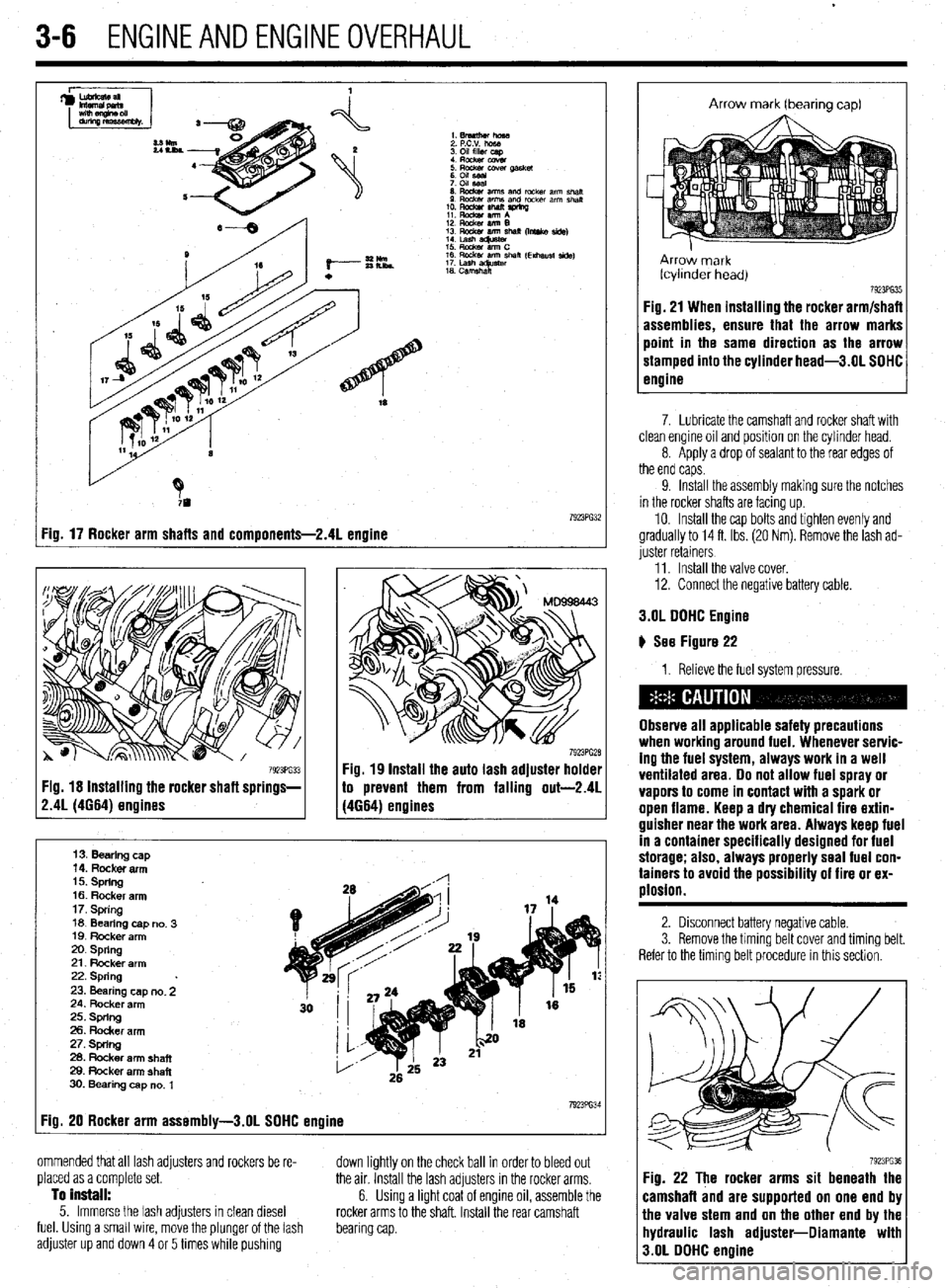
I Fig. 17 Rocker arm shafts and components-2.41 engine
Fig. 18 Installing the rocker shaft springs- 79231632
13. Bearing cap
14. Rocker arm
15. spring
16. Rocker arm
17. Spring
16 Bearing no. cap 3
IQ. Rocker arm
20. spring
21. Rocker arm
22. Spring
23. Bearing no. cap 2
24. Rocker arm
25. spring
26. Rocker arm
27. Spring
28. Rocker arm shaft
29. Rocker arm shaft
30. Bearing no. cap 1
Fig. 20 Rocker arm assembly-3.01 SOHC engine 7923PG3
ommended that all lash adjusters and rockers be re-
placed as a complete set.
To install:
5. Immerse the lash adjusters in clean diesel
fuel. Using a small wire, move the plunger of the lash
adjuster up and down 4 or 5 times while pushing down lightly on the check ball in order to bleed out
the air. Install the lash adjusters in the rocker arms.
6. Using a light coat of engine oil, assemble the
rocker arms to the shaft. Install the rear camshaft
bearing cap.
Arrow mark (bearing cap)
Arrow mark
fcyllnder head)
7923PG35 Fig. 21 When installing the rocker arm/shafi
assemblies, ensure that the arrow marks
point in the same direction as the arrow
stamped into the cylinder head-3.01 SOHC
engine
7. Lubricate the camshaft and rocker shaft with
clean engine oil and position on the cylinder head.
8. Apply a drop of sealant to the rear edges of
the end caps.
9. Install the assembly making sure the notches
in the rocker shafts are facing up.
10. Install the cap bolts and tighten evenly and
gradually to 14 ft. Ibs. (20 Nm). Remove the lash ad-
juster retainers
11. Install the valve cover.
12. Connect the negative battery cable.
3.OL OOHC Engine
) See Figure 22
1. Relieve the fuel system pressure.
Observe all applicable safety precautions
when working around fuel. Whenever servic-
ing the fuel system, always work in a well
ventilated area. 00 not allow fuel spray or
vapors to come in contact with a spark or
open flame. Keep a dty chemical fire extin-
guisher near the work area. Always keep fuel
in a container specifically designed for fuel
storage; also, always properly seal fuel con-
tainers to avoid the possibility of fire or ex-
plosion.
2. Disconnect battery negative cable.
3. Remove the timino belt cover and timina belt.
Refer to the timing belt procedure in this section.
7923PG3 Fig. 22 The rocker arms sit beneath the
camshaft and are supported on one end bl
the valve stem and on the other end by the
hydraulic lash adjuster-Oiamante wit1
3.OL OOHC engine
Page 86 of 408
ENGINEANDENGINEOVERHAUL 3-25
When removina the cvlinder head. take care
not to bend or iamag;! the plug guide. The
plug guide can not be replaced.
To install:
22. Thoroughly clean the mating surfaces of the
head and block.
23. Place a new head gasket on the cylinder
block with the identification marks facing upward. Do
not use sealer on the gasket.
24. Carefully install the cylinder head on the
block.
25. Measure the cylinder head bolts prior to in-
stallation Replace any that exceed 3.795 in.
(96.4mm)
26. Apply a small amount of engine oil to the
thread section of the bolt and install so the chamfer
of the washer faces upward.
27. Tighten the cylinder head bolts as follows:
a. In the proper tightening sequence, torque
bolts to 54 ft. Ibs. (75 Nm).
b. In the reverse order of the tightening se-
quence, fully loosen all bolts.
c In the proper trghtening sequence, torque
bolts to 14 ft. Ibs. (20 Nm).
d. In the proper tightening sequence, tighten
bolts 1/4 turn (90 degrees).
e. In the proper tightening sequence, tighten
bolts an additional 1/4 turn (90 degrees).
28. Install the camshaft sprocket and tighten the
bolt to 65 ft. Ibs (90 Nm), while holding the sprocket
in place using the appropriate wrench. Confirm
proper timing mark alignment.
29. Install the upper timing belt cover and rocker
cover. Torque the rocker cover bolts to 29 inch Ibs.
(3 Nm).
30. Loosen the water pipe mounting bolt for ease
of thermostat housing installation.
31. Apply a thin bead of sealant MD970389 or
equivalent, to the water tube connection on the ther-
mostat case.
32. Apply a small amount of water to the O-ring
of the water inlet pipe and press the thermostat case
assembly onto the water inlet pipe. Install the ther-
mostat case assembly mounting bolt tightening to 16
ff. Ibs. (22 Nm).
l ECT sensor and gauge sender l IAC motor 33. Tighten the water pipe mounting bolt.
34. Install the thermostat into the housing so the
jiggle valve is located at the top. Tighten the housing
bolts to 10 ft. Ibs (14 Nm).
35. Attach the wiring to the following compo-
nents:
l HO& sensor
l EGR temperature sensor l TP sensor l Knock sensor l Fuel injectors
36. Connect the upper radiator hose to the ther-
mostat housing.
37. Connect the accelerator cable connection to
the throttle body.
38. Connect the oil pressure switch.
39. Install the spark plug wires,
40. Connect the control harness assembly.
41. Replace the O-ring for the high pressure hose
and install a new clamp on the return hose and re-
connect the fuel lines. 42. Install the air intake hose. Connect the
breather hose and air cleaner case cover
43. Reconnect the brake booster and the PCV
vacuum hoses.
44. Fill the system with coolant.
45. Connect the negative battery cable
2.01 SOHC Engine
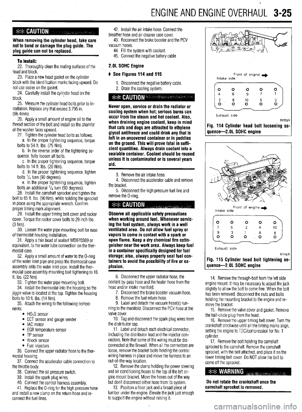
# See Figures 114 and 115
1. Disconnect the negative battery cable.
2. Drain the coolrng system.
Never open, service or drain the radiator or
cooling system when hot; serious burns can
occur from the steam and hot coolant. Also,
when draining engine coolant, keep in mind
that cats and dogs are attracted to ethylene
glycol antifreeze and could drink any that is
left in an uncovered container or in puddles
on the ground. This will prove fatal in suffi-
cient quantities. Always drain coolant into a
sealable container. Coolant should be reused
unless it is contaminated or is several years
old.
3. Remove the air intake hose.
4. Disconnect the accelerator cable and remove
the bracket.
5. Disconnect the high pressure fuel line and
remove the O-ring.
Observe all applicable safety precautions
when working around fuel. Whenever servic-
ing the fuel system, always work in a well
ventilated area. Do not allow fuel spray or
vapors to come in contact with a spark or
open flame. Keep a dry chemical fire extin-
guisher near the work area. Always keep fuel
in a container specifically designed for fuel
storage; also, always properly seal fuel con-
tainers to avoid the possibility of fire or ex-
plosion.
6. Disconnect the upper radiator hose, the
coolant by-pass hose and the heater hose from the
head and/or intake manifold.
7. Disconnect the brake booster vacuum hose.
8. Remove the fuel return hose.
9. Label and detach the vacuum hose(s) run-
ning to the manifold. Disconnect the PCV hose at the
valve cover.
10. Tag and disconnect the spark plug wires from
the drstnbutor cap
11. Label and detach each electrical connector,
including the distributor lead and the injector con-
nectors Note that some of the wiring must be drs-
connected at the firewall. When all the connectors are
loose, remove the bracket bolts holding the control
wiring harness rn place and move the harness to an
out-of-the-way location.
12. Remove the clamp holding the power steering
and air conditioning hoses to the top of the left en-
gine mount bracket. Move the hoses out of the way
but don’t drsconnect either hose from its system.
13. Position a floor lack and a broad piece of
lumber under the engine. Elevate the jack lust enough
to support the engine without raising it.
Front of engne I)
Intake side
~~
Exhaust side
93153~24 Fig. 114 Cylinder head bolt loosening se-
quence-2.01 SOHC engine
Front of engme I)
Intake side
Exhaust side
93153g25 Fig. 115 Cylinder head bolt tightening se-
quence-2.01 SDHC engine
14. Remove the through-bolt from the left side
engine mount. It may be necessary to adjust the jack
slightly to allow the bolt to come free When the bolt
has been removed, disconnect the nuts and bolts
holding the mounting bracket to the engine and re-
move the bracket
15. Remove the valve cover and gasket. Remove
the half-circle plug from the head.
16. Remove the upper timing belt cover. Turn the
crankshaft clockwise until all the timing marks align,
setting the engine to TDUcompression for No. 1
cylinder.
17. Remove the bolt holding the camshaft
sprocket to the camshaft. Remove the camshaft
sprocket, with the belt attached, and place it on the
lower timing belt cover. Do NOT allow the belt to
come off the sprocket
Do not rotate the crankshaft once the
camshaft sorocket is removed.
Page 87 of 408
3-26 ENGINEANDENGINEOVERHAUL
18. Remove the self-locking nuts and the small
retaining bolt holding the exhaust pipe to the bottom
of the exhaust manifold. Separate the pipe from the
manifold and remove the gasket.
19. Remove the bolts holding the support brace
to the bottom of the intake manifold.
20. Use the special hex wrench (MB 998051-01)
and loosen the head bolts in the order shown in 2 or
3 passes. When all are finger loose, remove the bolts.
21. Rock the head gently to break it loose; if tap-
ping is necessary, do so with a rubber or wooden
mallet at the corners of the head. DO NOT pry the
head up by wedging tools between the head and the
block.
22. Lift the head free of the engine. It is coming
off with both manifolds and the intake plenum at-
tached; the help of an assistant is recommended for
lifting. Support the head assembly on wooden blocks
on a suitable workbench. Refer to Cleaning and In-
spection in this section for work to be done before in-
stalling the head. If the head has been removed for
work other than gasket replacement, the rocker as-
sembly and camshaft or other components may be
removed.
Before reinstallation, the head should be com-
pletely assembled on the bench. This allows proper
location and tightening of all the external items.
To install: 23. Place a new gasket on the engine so that the
identifying mark faces up (towards the head) and is at
the timing belt end of the block. Install a new gasket
on the exhaust pipe.
Do not apply sealant to the head gasket or
mating surfaces.
24. Install the head straight down onto the block.
Try to eliminate most of the side-to-side adjust-
ments as this may move the gasket out of position.
Install the bolts by hand and just start each bolt 1 or
2 turns on the threads.
25. The head bolt torque specification is 68 ft.
Ibs. (92 Nm) for a cold engine. The bolts must be
tightened in the order shown in 3 steps. On the first
pass, tighten all the bolts to about 22 ft. Ibs. (30 Nm),
then proceed through the order tightening each bolt
to about 45 ft. Ibs. (61 Nm). The final torque is
achieved on the third pass.
26. Install the intake manifold support brace to
the manifold and tighten the bolts to 16 ft. Ibs. (22
Nm). 27. Making sure the gasket is still in place, con-
nect the exhaust pipe to the base of the exhaust man-
ifold. Use new self-locking nuts; tighten the nuts and
the small bracket bolt to 26 ft. Ibs. (35 Nm).
28. Make sure the camshaft has not changed po-
sition during repalrs. Carefully install the camshaft
sprocket and belt onto the camshaft. Tighten the re-
taining bolt to 66 ft. Ibs. (91 Nm).
29. Install the upper timing belt cover, then
tighten the bolts to 8 ft. Ibs. (11 Nm).
30. Apply sealant to the contact surfaces of the
half-circle plug and install the plug in the head In-
stall the valve cover and gasket.
31. Install the engine mount bracket to the en-
gine. Tighten the mounting nuts and bolts to 42 ft.
Ibs. (57 Nm).
32. Adjust the jack (if necessary) so that the en-
gine mount bushing aligns with the bodywork
bracket. Install the through-bolt and tighten the nuts
snug.
33. Slowly release tension on the floor jack so
that the weight of the engine bears fully on the
mount. Tighten the through-bolt to 52 ft. Ibs. (71
Nm) and the small safety nut to 26 ft. tbs. (36 Nm).
34. Install the bracket holding the power steering
hose and air conditioning hose to the top of the en-
gine mount.
35. Position the control wiring harness and in-
stall the retaining bolts. Attach each electrical con-
nector to its proper location, making sure the wires
are properly routed and firmly connected.
36. Install the spark plug wires in the distributor
cap.
37. Connect the PCV hose and the vacuum
hose(s).
38. Connect the fuel return line. Connect the
brake booster vacuum hose.
39. Install the heater hose, the coolant by-pass
hose and.the upper radiator hose. Pay close attention
to the position and routing of these hoses and insure
that they are not crimped or constricted. Install the
clamps in the same location as before removal.
40. Install a new O-ring on the high pressure fuel
line and lubricate it with a coating of gasoline. Care-
fully connect the high pressure fuel line to the fuel
rail, taking care not to damage the O-ring. Tighten the
bolts only to 4 ft. Ibs. (6 Nm).
41. Connect the accelerator cable and adjust it as
necessary.
42. Install the air intake hose.
43. Fill the cooling system with coolant.
44. Changing the oil and filter is recommended
to eliminate pollutants in the oil.
Intake side
I Front of
engine
Exhaust side
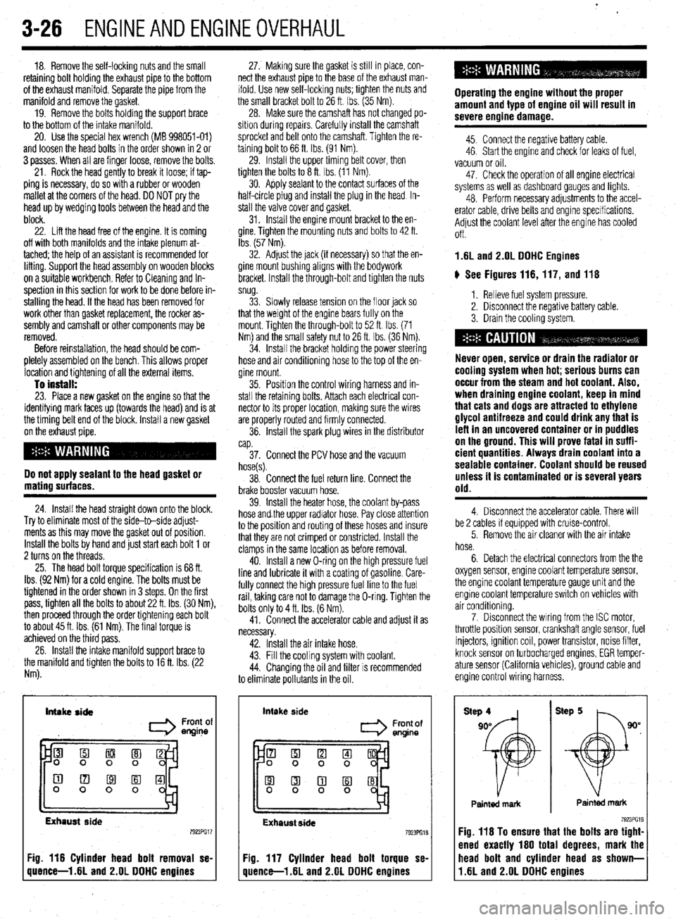
Fig. 116 Cylinder head bolt removal se-
quence-l .6L and 2.OL DDHC engines intake
side
Front of
entine
Exhaust side 7923PG18
Fig. 117 Cylinder head bolt torque se-
quence-l .6L and 2.OL DDHC engines Operating the engine without the proper
amount and type of engine oil will result in
severe engine damage.
45. Connect the negative battery cable.
46. Start the engine and check for leaks of fuel,
vacuum or oil.
47. Check the operation of all engine electrical
systems as well as dashboard gauges and lights.
48. Perform necessary adjustments to the accel-
erator cable, drive belts and engine specifications.
Adjust the coolant level after the engine has cooled
Off.
1.6L and 2.OL DDHC Engines
ti See Figures 116,117, and 116
1. Relieve fuel system pressure.
2. Disconnect the negative battery cable.
3. Drain the cooling system.
Never open, service or drain the radiator or
cooling system when hot; serious burns can
occur from the steam and hot coolant. Also,
when draining engine coolant, keep in mind
that cats and dogs are attracted to ethylene
glycol antifreeze and could drink any that is
left in an uncovered container or in puddles
on the ground. This will prove fatal in suffi-
cient quantities. Always drain coolant into a
sealable container. Coolant should be reused
unless it is contaminated or is several years
old.
4. Disconnect the accelerator cable. There will
be 2 cables if equipped with cruise-control.
5. Remove the air cleaner with the air intake
hose.
6. Detach the electrical connectors from the the
oxygen sensor, engine coolant temperature sensor,
the engine coolant temperature gauge unit and the
engine coolant temperature switch on vehicles with
air conditioning.
7. Disconnect the wiring from the ISC motor,
throttle position sensor, crankshaft angle sensor, fuel
injectors, ignition coil, power transistor, noise filter,
knock sensor on turbocharged engines, EGR temper-
ature sensor (California vehicles), ground cable and
engine control wiring harness.
Painted mark Painted mark
Fig. 116 To ensure that the bolts are tight-
ened exactly 160 total degrees, mark the
11.6L and 2.OL DDHC engines head bolt and cylinder head as shown-
Page 111 of 408
.
3-50 ENGINEANDENGINEOVERHALJL
F
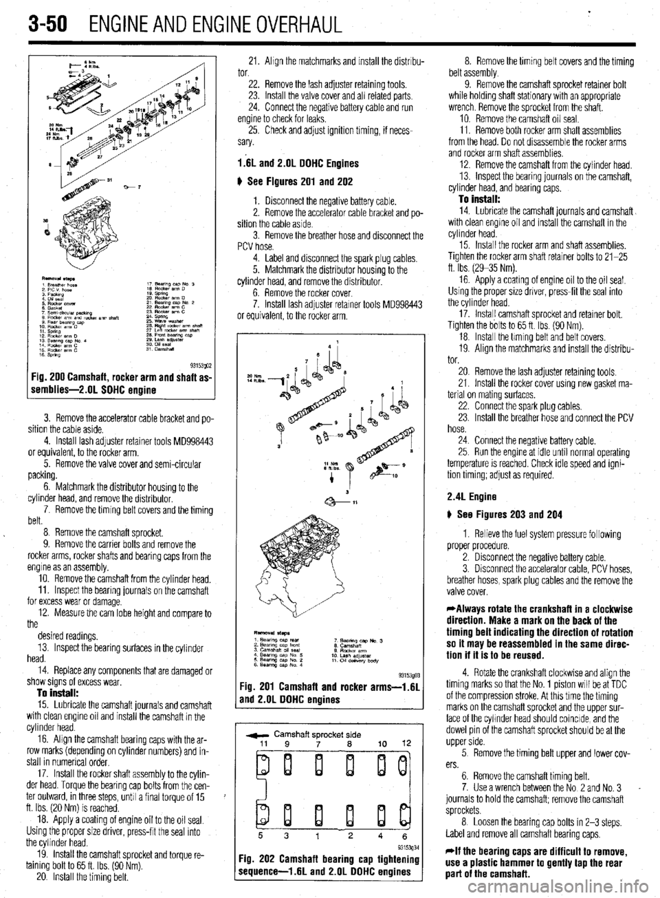
1 s 93153QO2 :ig. 200 Camshaft, rocker arm and shaft as-
iemblies-2.01 SOHC ermine
3. Remove the accelerator cable bracket and po-
sition the cable aside.
4. Install lash adjuster retainer tools MD998443
or equivalent, to the rocker arm.
5. Remove the valve cover and semi-circular
packing.
6. Matchmark the distributor housing to the
cylinder head, and remove the distributor,
7. Remove the timing belt covers and the timing
belt.
8 Remove the camshaft sprocket.
9. Remove the carrier bolts and remove the
rocker arms, rocker shafts and bearing caps from the
engine as an assembly.
10. Remove the camshaft from the cylinder head.
11. Inspect the bearing journals on the camshaft
for excess wear or damage.
12. Measure the cam lobe height and compare to
the
desired readings.
13. Inspect the bearing surfaces in the cylinder
head.
14. Replace any components that are damaged or
show signs of excess wear,
To install:
15. Lubricate the camshaft journals and camshaft
with clean engine oil and install the camshaft in the
cylinder head.
16. Align the camshaft bearing caps with the ar-
row marks (depending on cylinder numbers) and in-
stall in numerical order,
17. Install the rocker shaft assembly to the cylin-
der head. Torque the bearing cap bolts from the cen-
ter outward, in three steps, unh a final torque of 15
ft. Ibs. (20 Nm) is reached.
18. Apply a coating of engine oil to the oil seal.
Using the proper size driver, press-frt the seal into
the cylinder head.
19. install the camshaft sprocket and torque re-
taining bolt to 65 ft. Ibs. (90 Nm).
20. Install the timing belt. 21. Ahgn the matchmarks and install the distrrbu- 8. Remove the timing belt covers and the timing
tor. belt assembly.
22. Remove the lash adjuster retaining tools.
23. Install the valve cover and all related parts
24. Connect the negative battery cable and run
engine to check for leaks,
25. Check and adjust ignition timing, if neces-
sary.
l.‘6L and 2.lJL DOHC Engines
6 See Figures 201 and 202
1. Disconnect the negative battery cable.
2. Remove the accelerator cable bracket and po-
sition the cable aside.
3. Remove the breather hose and disconnect the
PCV hose. 9. Remove the camshaft sprocket retainer bolt
while holding shaft stationary with an appropriate
wrench. Remove the sprocket from the shaft.
10. Remove the camshaft oil seal.
11. Remove both rocker arm shaft assemblies
from the head. Do not drsassemble the rocker arms
and rocker arm shaft assemblies.
12. Remove the camshaft from the cylinder head.
13. inspect the bearing journals on the camshaft,
cylinder head, and bearing caps.
To install:
14. Lubricate the camshaft journals and camshaft
with clean engine oil and install the camshaft in the
cylinder head.
4. Label and disconnect the spark plug cables.
5. Matchmark the distributor housing to the
cylinder head, and remove the distributor.
6. Remove the rocker cover.
7. Install lash adjuster retarner tools MD998443
or equivalent, to the rocker arm. 15. Install the rocker arm and shaft assemblies.
Tighten the rocker arm shaft retainer bolts to 21-25
ft. Ibs. (2935 Nm).
16 Apply a coating of engine oil to the oil seal.
Using the proper size driver, press-fit the seal into
the cylinder head.
17. Instal! camshaft sprocket and retainer bolt.
Tighten the bolts to 65 ft. Ibs. (90 Nm).
18. Install the hming belt and belt covers.
19. Align the matchmarks and install the distribu-
tor.
93153gO: :ig. 201 Camshaft and rocker arms-i.61
rnd 2.OL DOHC engines
r ,
w Camshaft sprocket side
ei i i ij
20. Remove the lash adjuster retaining tools,
21. Install the rocker cover using new gasket ma-
terial on mating surfaces,
22. Connect the spark plug cables.
23. Install the breather hose and connect the PCV
hose.
24. Connect the negative battery cable.
25. Run the engme at idle until normal operating
temperature is reached. Check idle speed and igni-
tion timing; adjust as required.
2.4L Engine
) See Figures 203 and 204
1. Relieve the fuel system pressure following
proper procedure.
2. Disconnect the negative battery cable.
3. Disconnect the accelerator cable, PCV hoses,
breather hoses, spark plug cables and the remove the
valve cover.
*Always rotate the crankshaft in a clockwise
direction. Make a mark on the back of the
timing belt indicating the direction of rotation
so it may be reassembled in the same direc-
tion if it is to be reused.
4. Rotate the crankshaft clockwise and align the
timing marks so that the No. 1 piston will be at TDC
of the compression stroke. At this time the timing
marks on the camshaft sprocket and the upper sur-
face of the cyhnder head should coincide, and the
dowel pin of the camshaft sprocket should be at the
upper side.
5 Remove the timing belt upper and lower cov-
ers.
6. Remove the camshaft timing belt.
7. Use a wrench between the No 2 and No. 3
journals to hold the camshaft; remove the camshaft
sprockets.
8 Loosen the bearing cap bolts in 2-3 steps.
Label and remove all camshaft bearing caps,
*If the bearing caps are difficult to remove,
use a plastic hammer to gently tap the rear
part of the camshaft.
Page 112 of 408
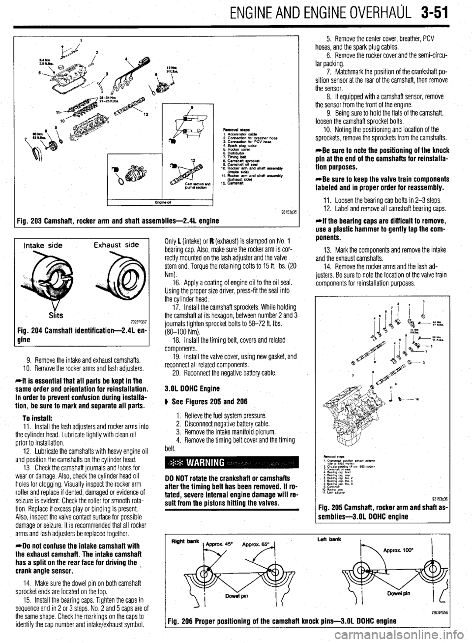
ENGlNEANDENGlNEOVERHALiL 3-51
:ig. 203 Camshaft, rocker arm and shaft assemblies-2.41 engine 9315393'
Intake side Exhaust side
7923PG57 Fig. 204 Camshaft identification-2.41 en-
gine
9. Remove the intake and exhaust camshafts.
10. Remove the rocker arms and lash adjusters
*It is essential that all parts be kept in the
same order and orientation for reinstallation.
In order to prevent confusion during installa-
tion, be sure to mark and separate all parts.
To install:
11. Install the lash adjusters and rocker arms into
the cylinder head. Lubricate lightly with clean oil
prior to installation.
12. Lubricate the camshafts with heavy engine oil
and position the camshafts on the cylinder head.
13 Check the camshaft journals and lobes for
wear or damage. Also, check the cylinder head oil
holes for clogging. Visually inspect the rocker arm
roller and replace if dented, damaged or evidence of
seizure is evident. Check the roller for smooth rota-
tion. Replace If excess play or binding is present.
Also, inspect the valve contact surface for possible
damage or seizure. It is recommended that all rocker
arms and lash adjusters be replaced together.
*Do not confuse the intake camshaft with
the exhaust camshaft. The intake camshaft
has a split on the rear face for driving the ,
crank angle sensor.
14. Make sure the dowel pin on both camshaft
sprocket ends are located on the top.
15. Install the bearing caps. Tighten the caps in
sequence and rn 2 or 3 steps. No 2 and 5 caps are of
the same shape. Check the markings on the caps to
identify the cap number and intake/exhaust symbol. Only 1 (intake) or I? (exhaust) is stamped on No. 1
bearing cap Also, make sure the rocker arm is cor-
rectly mounted on the lash adjuster and the valve
stem end. Torque the retaining bolts to 15 ft. Ibs. (20
Nm).
16. Apply a coating of engine oil to the oil seal.
Using the proper size driver, press-fit the seal into
the cylinder head.
17. Install the camshaft sprockets. While holding
the camshaft at its hexagon, between number 2 and 3
journals tighten sprocket bolts to 58-72 ft. Ibs.
(80-l 00 Nm).
18. Install the timing belt, covers and related
components.
19. Install the valve cover, using new gasket, and
reconnect all related components
20. Reconnect the negative battery cable.
3.OL DOHC Engine
# See Figures 205 and 206
1. Relieve the fuel system pressure.
2. Disconnect negative battery cable.
3. Remove the intake manifold plenum.
4. Remove the timing belt cover and the timing
belt.
DO NOT rotate the crankshaft or camshafts
after the timing belt has been removed. If ro-
tated, severe internal engine damage will re-
sult from the pistons hitting the valves.
5. Remove the center cover, breather, PCV
hoses, and the spark plug cables.
6. Remove the rocker cover and the semi-circu-
lar packing.
7. Matchmark the position of the crankshaft po-
sition sensor at the rear of the camshaft, then remove
the sensor.
8. If equipped with a camshaft sensor, remove
the sensor from the front of the engine.
9 Being sure to hold the flats of the camshaft,
loosen the camshaft sprocket bolts.
10. Noting the positionmg and location of the
sprockets, remove the sprockets from the camshafts.
*Be sure to note the positioning of the knock
pin at the end of the camshafts for reinstalla-
tion purposes.
*Be sure to keep the valve train components
labeled and in proper order for reassembly.
11. Loosen the bearing cap bolts in 2-3 steps.
12. Label and remove all camshaft bearing caps.
*If the bearing caps are difficult to remove,
use a plastic hammer to gently tap the com-
ponents.
13. Mark the components and remove the intake
and the exhaust camshafts.
14. Remove the rocker arms and the lash ad-
justers. Be sure to note the location of the valve train
components for reinstallation purposes.
1 semblies-3.01 DOHC engine
I
Left bank
7923PG58 Fig. 206 Proper positioning of the camshaft knock pins-3.01 DOHC engine
Page 145 of 408
4-2 DRIVEABILITYAND EMISSIONS CONTROLS
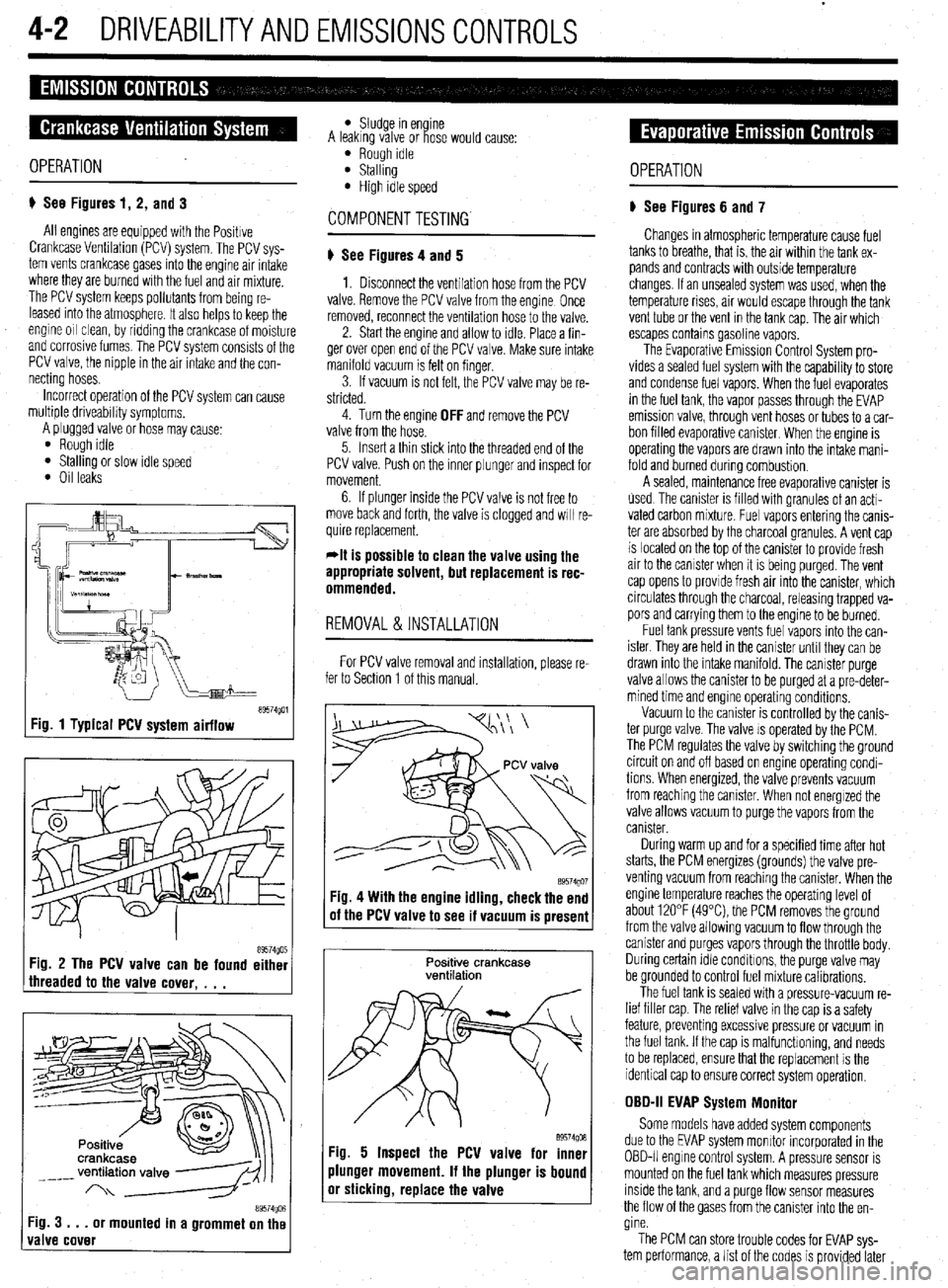
OPERATION
p See Figures 1, 2, and 3
All engines are equipped with the Positive
Crankcase Venhlation (PCV) system. The PCV sys-
tem vents crankcase gases into the engine air intake
where they are burned with the fuel and air mrxture.
The PCV system keeps pollutants from being re-
leased into the atmosphere It also helps to keep the
engine 011 clean, by ridding the crankcase of moisture
and corrosive fumes. The PCV system consists of the
PCV valve, the nipple in the air intake and the con-
necting hoses.
Incorrect operation of the PCV system can cause
multiple driveability symptoms.
A plugged valve or hose may cause’
l Rough Idle l Stalling or slow idle speed l Oil leaks
tT9574goi Fig. 1 Typical PCV system airflow
89574g0r5 Fig. 3 . . .
or mounted in a grommet on the
valve cover
l Sludge in en ine
A leakrng valve or ose would cause: i?
l Rough idle l Stalling l High idle speed
p See Figures 4 and 5
1. Disconnect the ventilation hose from the PCV
valve. Remove the PCV valve from the engine Once
removed, reconnect the ventilation hose to the valve.
2. Start the engine and allow to idle. Place a fin-
ger over open end of the PCV valve. Make sure intake
manifold vacuum is felt on finger.
3. If vacuum is not felt, the PCV valve may be re-
stricted.
4. Turn the engine
OFF and remove the PCV
valve from the hose.
5. Insert a thin stick into the threaded end of the
PCV valve. Push on the inner plunger and inspect for
movement.
6. If plunger inside the PCV valve is not free to
move back and forth, the valve is clogged and WIII re-
quire replacement.
*It is possible to clean the valve using the
appropriate solvent, but replacement is rec-
ommended.
REMOVAL&INSTALLATION
For PCV valve removal and installation, please re-
fer to Section 1 of this manual.
89574QO’ Fig. 4 With the engine idling, check the end
of the PCV valve to see if vacuum is present
Positive crankcase
ventilation
89574go6 Fig. 5 Inspect the PCV valve for inner
plunger movement. If the plunger is bound
or sticking, replace the valve OPERATION
p See Figures 6 and 7
Changes in atmospheric temperature cause fuel
tanks to breathe, that is, the air within the tank ex-
pands and contracts with outside temperature
changes. If an unsealed system was used, when the
temperature rises, air would escape through the tank
vent tube or the vent in the tank cap. The air which
escapes contains gasoline vapors.
The Evaporative Emission Control System pro-
vides a sealed fuel system with the capability to store
and condense fuel vapors. When the fuel evaporates
in the fuel tank, the vapor passes through the EVAP
emission valve, through vent hoses or tubes to a car-
bon filled evaporative canister. When the engine is
operahng the vapors are drawn into the intake mani-
fold and burned during combustion.
A sealed, maintenance free evaporative canister is
used The canister is filled wrth granules of an acti-
vated carbon mixture. Fuel vapors entering the canis-
ter are absorbed by the charcoal granules. A vent cap
is located on the top of the canister to provide fresh
air to the canister when it is being purged. The vent
cap opens to provide fresh air into the canister, which
circulates through the charcoal, releasing trapped va-
pors and carrying them to the engine to be burned.
Fuel tank pressure vents fuel vapors into the can-
ister. They are held in the canister until they can be
drawn into the intake manifold. The canister purge
valve allows the canister to be purged at a pre-deter-
mined time and engine operating conditions.
Vacuum to the canister is controlled by the canis-
ter purge valve. The valve IS operated by the PCM.
The PCM regulates the valve by switching the ground
circuit on and off based on engine operating condi-
tions When energized, the valve prevents vacuum
from reaching the canister. When not energized the
valve allows vacuum to purge the vapors from the
canister.
During warm up and for a specified time after hot
starts, the PCM energizes (grounds) the valve pre-
venting vacuum from reaching the canrster. When the
engine temperature reaches the operating level of
about 120°F (49°C) the PCM removes the ground
from the valve allowing vacuum to flow through the
canister and purges vapors through the throttle body.
During certain Idle conditions, the purge valve may
be grounded to control fuel mixture calibrations.
The fuel tank is sealed with a pressure-vacuum re-
lief filler cap. The relief valve in the cap is a safety
feature, preventing excessive pressure or vacuum in
the fuel tank. If the cap is malfunctioning, and needs
to be replaced, ensure that the replacement is the
identical cap to ensure correct system operation,
OBD-II EVAP System Monitor
Some models have added system components
due to the EVAP system monitor incorporated in the
OBD-II engrne control system. A pressure sensor is
mounted on the fuel tank which measures pressure
inside the tank, and a purge flow sensor measures
the flow of the gases from the canister into the en-
gine.
The PCM can store trouble codes for EVAP sys-
tem performance, a list of the codes is provided later
Page 151 of 408
.
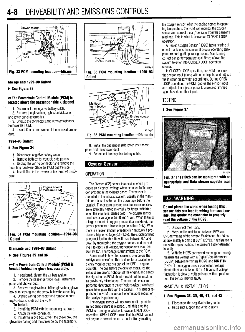
4-8 DRIVEABILITYAND EMISSIONS CONTROLS
93154g17 Fig. 33 PCM mounting location-Mirage
Mirage and 1999-00 Galant
) See Figure 33
*The Powertrain Control Module (PCM) is
located above the passenger side kickpanel.
1. Disconnect the negative battery cable.
2. Remove the @love box, right side kickpanel
and lower panel assemblies.
3. Unplug the connectors and remove fasteners.
Remove the PCM.
4. Installation is the reverse of the removal proce-
dure.
1994-98 Galant
+ See Figure 34
1, Disconnect negative battery cable.
2. Remove both center console side panels.
3. Unplug the wiring connector and remove the
mounting hardware. Slide the PCM out the side.
4. installation is the reverse of the removal proce-
dure.
Diamante and 1990-93 Galant
) See Figures 35 and 38
*The Powertrain Control Module (PCM) is
located behind the glove box assembly.
1, If equipped, disarm the air bag system
2. Remove the passenger side lower instrument
panel and shower duct.
3. Remove the glove box striker, glove box, glove
box outer casing and the screw below the assembly.
4. Unplug wiring connector and remove mount-
ing hardware. Slide out the PCM.
To install: 5. Install the PCM with the mounting hardware.
6. Attach the wire connector.
7. Install the glove box striker, the glove box, the
glove box casing and the screw below the assembly.
Q3154g15 Fig. 35 PCM mounting location-1990-93
Galant
93154g16 Fig. 38 PCM mounting location-Diamante
8. Install the passenger side lower instrument
panel and the shower duct.
9. Reconnect the negative battery cable
OPERATION
The Oxygen (02) sensor is a device which pro-
duces an electrical voltage when exposed to the oxy-
gen present in the exhaust gases. The sensor is
mounted in the exhaust system, usually in the mani-
fold or a boss located on the down pipe before the
catalyst. The oxygen sensors used on some models
are electrically heated internally for faster switching
when the engine is started cold. The oxygen sensor
produces a voltage within 0 and 1 volt. When there is
a large amount of oxygen present (lean mixture), the
sensor produces a low voltage (less than 0.4~). When
there is a lesser amount present (rich mixture) it pro-
duces a higher voltage (0.6-I .Ov). The stoichiometric
or correct fuel to air ratio will read between 0.4 and
0.6~. By monitoring the oxygen content and convert-
ing it to electrical voltage, the sensor acts as a rich-
lean switch. The voltage is transmitted to the PCM.
Some models have two sensors, one before the
catalyst and one after. This is done for a catalyst eff i-
ciency monitor that is a part of the OBD-II engine
controls. The one before the catalyst measures the
exhaust emissions right out of the engine, and sends
the signal to the PCM about the state of the mixture
as previously talked about. The second sensor re-
ports the difference in the emissions after the exhaust
gases have gone through the catalyst. This sensor re-
ports to the PCM the amount of emissions reduction
the catalyst is performing.
The oxygen sensor will not work until a predeter-
mined temperature is reached, until this time the
PCM is running in what as known as OPEN LOOP
operation. OPEN LOOP means that the PCM has not
yet begun to correct the air-to-fuel ratio by reading the oxygen sensor. After the engine comes to operat-
ing temperature, the PCM will monitor the oxygen
sensor and correct the air/fuel ratio from the sensor’s
readings. This is what is known as CLOSED LOOP
operation.
A Heated Oxygen Sensor (H02S) has a heating el-
ement that keeps the sensor at proper operatmg tem-
perature during all operating modes. Maintaining
correct sensor temperature at all times allows the
system to enter into CLOSED LOOP operation
sooner.
In CLOSED LOOP operation, the PCM monitors
the sensor input (along with other inputs) and adjusts
the injector pulse width accordingly. During OPEN
LOOP operation, the PCM ignores the sensor input
and adjusts the injector pulse to a preprogrammed
value based on other inputs.
TESTING
# See Figure 37
93154p36 Fig. 37 The HD2S can be monitored with an
appropriate and Data-stream capable scan
tool
Do not pierce the wires when testing this
sensor; this can lead to wiring harness dam-
age. Backprobe the connector to properly
read the voltage of the HD2S.
1. Disconnect the H02S.
2. Measure the resistance between PWR and
GND terminals of the sensor. Resistance should be
approximately 6 ohms at 68°F (20°C) If resistance is
not within specification, the sensor’s heater element
is faulty.
3. With the H02S connected and engine running,
measure the voltage with a Digital Volt-Ohmmeter
(DVOM) between terminals
HD2S and SIG RTN (GND) of the oxygen sensor connector. Voltage
should fluctuate between 0.01-l .O volts. If voltage
fluctuation is slow or voltage is not within specifica-
tion, the sensor may be faulty.
REMOVAL &INSTALLATION
) See Figures 38, 39, 40, 41, and 42
1. Disconnect the negative battery cable
2. Raise and support the vehicle safely.
Page 153 of 408
4-10 DRIVEABILITYAND EMISSIONS CONTROLS
I
OPERATION
The Engine Coolant Temperature (ECT) sensor re-
sistance changes in response to engine coolant tem-
perature. The sensor resistance decreases as the
coolant temperature increases, and increases as the
coolant temperature decreases. This provides a refer-
ence signal to the PCM, which indicates engine
coolant temperature. The signal sent to the PCM by
the ECT sensor helps the PCM to determine spark-
advance, EGR flow rate, air/fuel ratio, and engine
temperature. The ECT is a two wire sensor, a 5volt
3. Place the temperature sensing portion of the
sensor into a pan of hot water. Use a thermometer to
monitor the water temperature.
4. Measure the resistance across the sensor ter-
minals while the sensor is in the water. Comoare ob- Fig. 47 Another method of testing the EC1 Fig. 50 Use a deep socket and an extension
is to submerge it in cold or hot water and to reach the ECT sensor. 1 ,
reference signal is sent to the sensor and the signal
return is based upon the change in the measured re-
sistance due to temperature. 1 check resistance
TESTING
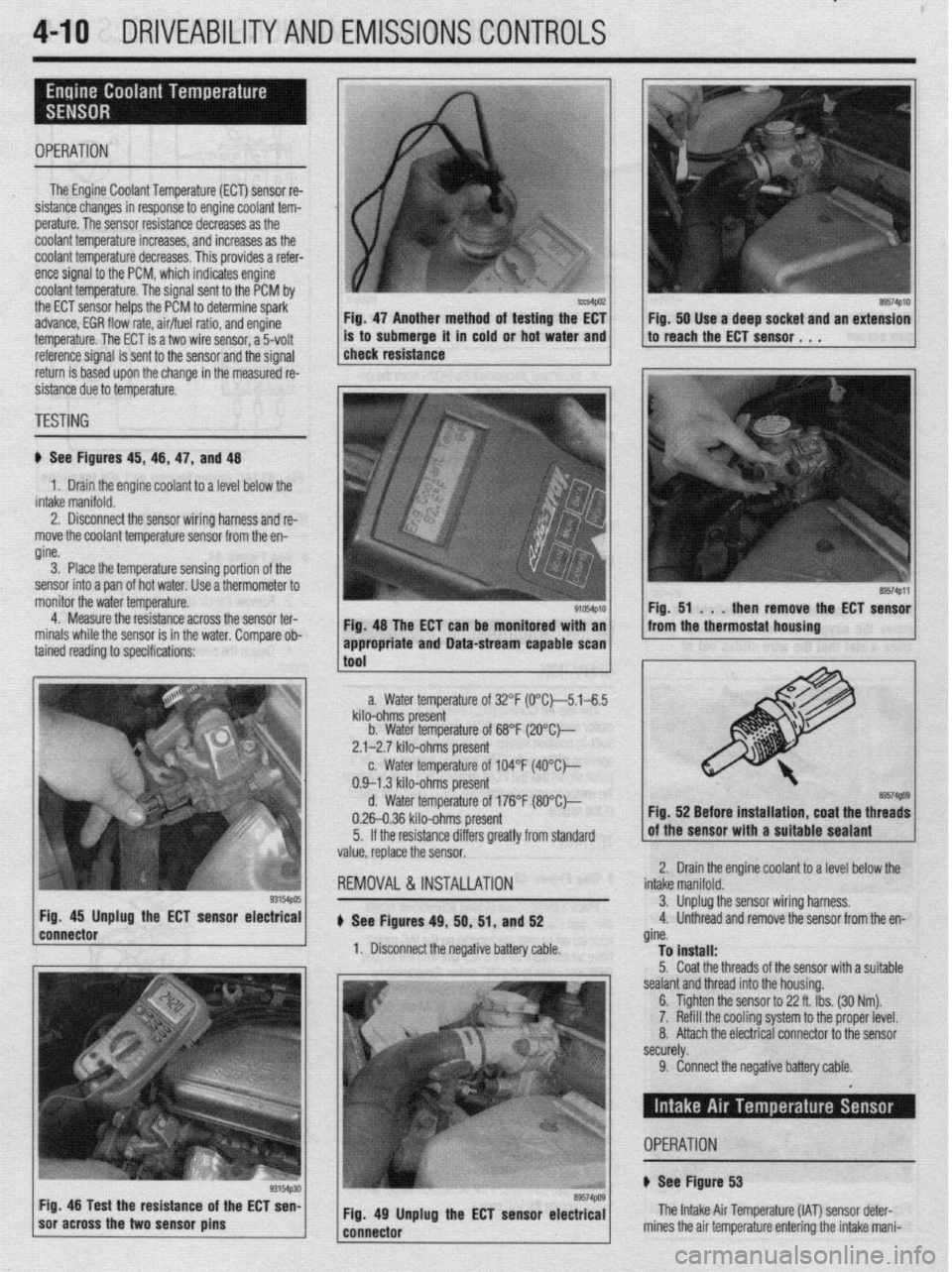
ti See Figures 45, 46, 47, and 48
1. Drain the engine coolant to a level below the
intake manifold.
2. Disconnect the sensor wiring harness and re-
move the coolant temperature sensor from the en-
gine.
Fig. 48 The ECT can be monitored with an
tained reading to specifications: ’
93154pos Fig. 45 Unplug the ECT sensor electrical
connector
1 soracross the two sensor pins g3154p30 Fig 48 Test the resistance of the ECT sen-
89574PlO
89574Pll
Fig. 51 . . .
then remove the ECT sensor
from the thermostat housing
a. Water temperature of 32°F (0°C~5.1-6.5
kilo-ohms present
b. Water temperature of 68°F (2O”C)--
2.1-2.7 kilo-ohms present
c. Water temperature of 104°F (4O”C)---
0.9-l .3 kilo-ohms present
d. Water temperature of 176°F (8O”Ck,
0.26-0.36 kilo-ohms present
5. If the resistance differs greatly from standard
value, replace the sensor.
REMOVAL &INSTALLATION
u See Figures 49, 50, 51, and 52
1. Disconnect the negative battery cable. Fig. 52 Before installation, coat the threads
Iolant to a level below the 2. Drain the engine c(
intake manifold.
3. Unplug1 the sensor wiring harness,
4. Unthreac
d and remove the sensor from the en-
gine.
To install:
5. Coat the threads of the sensor with a suitable
sealant and thread into the housing.
6. Tighten the sensor to 22 ft. Ibs. (30 Nm).
7. Refill the cooling system to the proper level.
8. Attach the electrical connector to the sensor
securely. appropriate and Data-stream capable scan 1
1
tnnl
9. Connect the negative battery cable.
Fig. 49 Unplug the ECT sensor electrical
---..^-s-- The Intake Air Temperature (IAT) sensor det
mines the air temnerature enterinn the! intake n er-
- ._ r_ -.-._ _. ._. J . _ ..-. ._
iani- OPERATION
+ See Figure 53