1900 MITSUBISHI DIAMANTE check engine
[x] Cancel search: check enginePage 146 of 408
DRIVEABILITYAND EMISSIONS CONTROLS 4-3
895?4Q3:
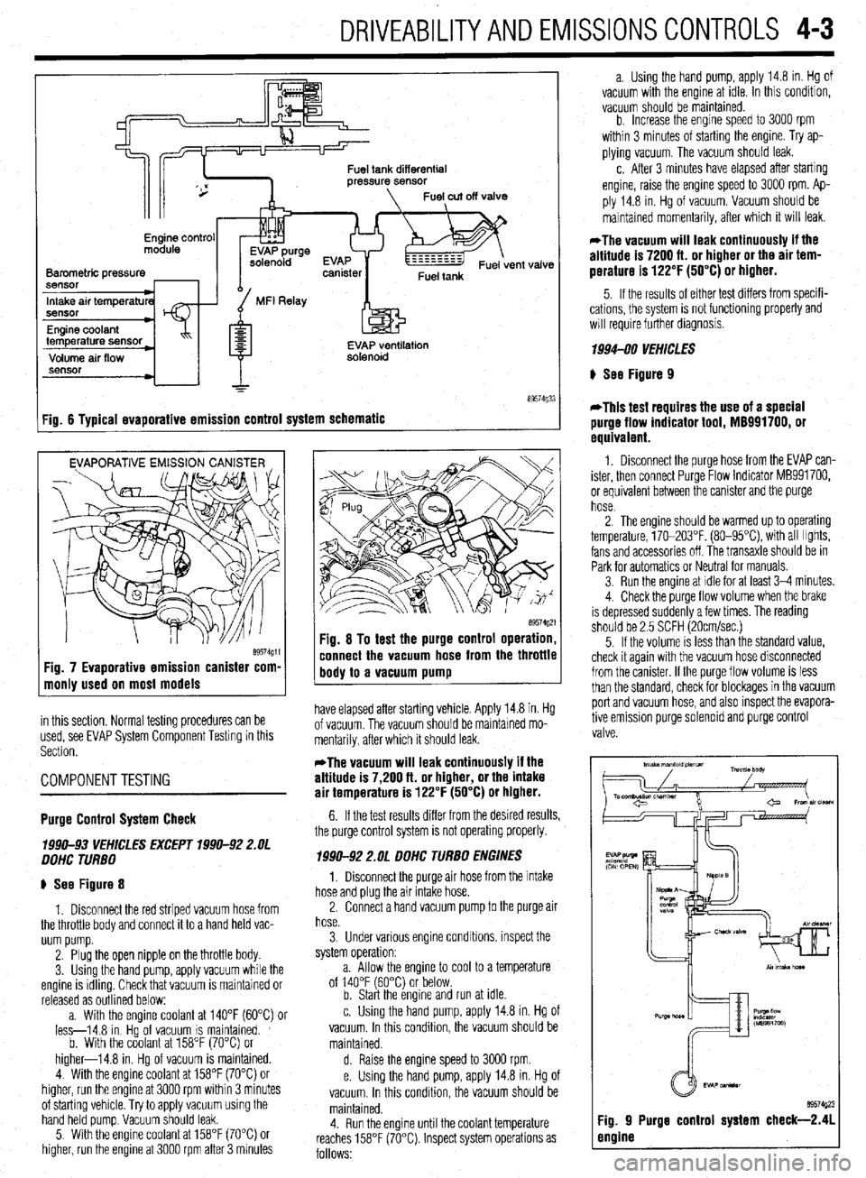
Fig. 6 Tvoical evaoorative emission control system schematic
EVAPORATIVE EMISSION CANISTER
Fig. 7 Evaporative emission canister com-
monly used on most models
in this section. Normal testing procedures can be
used, see EVAP System Component Testing in this
Section.
COMPONENTTESTING
89574g21 Fig. 8 To test the purge control operation,
connect the vacuum hose from the throttle
body to a vacuum pump
have elapsed after starting vehicle. Apply 14.8 in. Hg
of vacuum. The vacuum should be maintained mo-
mentarily, after which it should leak.
*The vacuum will leak continuously if the
altitude is 7,200 ft. or higher, or the intake
air temperature is 122°F (50°C) or higher.
Purge Control System Check
lB!M-93 VEHKLES EXCEPT 39911-92 2.UL
DDHC TURBO
p See Figure 8
1. Disconnect the red striped vacuum hose from
the throttle body and connect it to a hand held vac-
uum pump.
2. Plug the open nipple on the throttle body.
3. Using the hand pump, apply vacuum while the
engine is idling. Check that vacuum is maintained or
released as outlined below:
a. With the enaine coolant at 140°F f6O”C) or
less-14.8 in Hgof vacuum IS maintained. ’
b. With the coolant at 158°F (70°C) or
higher-14.8 in. Hg of vacuum is maintained.
4. With the engine coolant at 158°F (70°C) or
higher, run the engine at 3000 rpm within 3 minutes
of starting vehicle. Try to apply vacuum using the
hand held pump. Vacuum should leak.
5. With the engine coolant at 158°F (70°C) or
higher, run the engine at 3000 rpm after 3 minutes 6. If the test results differ from the desired results,
the purge control system is not operating properly.
199042 2.OL DDHC TURBO ENGINES
1, Disconnect the purge air hose from the intake
hose and plug the air intake hose.
2. Connect a hand vacuum pump to the purge air
hose.
3. Under various engine condrtions, inspect the
system operation:
a. Allow the engine to cool to a temperature
of 140°F (60°C) or below.
b. Start the engine and run at idle.
c. Using the hand pump, apply 14.8 in. Hg of
vacuum. In this condition, the vacuum should be
maintained.
d. Raise the engine speed to 3000 rpm.
e. Using the hand pump, apply 14.8 in. Hg of
vacuum. In this condition, the vacuum should be
maintained.
4. Run the engine until the coolant temperature
reaches 158°F (70°C). Inspect system operations as
follows: a. Using the hand pump, apply 14.8 in. Hg of
vacuum with the engine at idle. In this condition,
vacuum should be maintained.
b. Increase the enaine soeed to 3000 rpm
within 3 minutes of st&ting’the engine. Try ap-
plying vacuum. The vacuum should leak.
c. After 3 minutes have elapsed after starting
engine, raise the engine speed to 3000 rpm. Ap-
ply 14.8 in. Hg of vacuum. Vacuum should be
maintained momentarily, after which it will leak.
*The vacuum will leak continuously if the
altitude is 7200 ft. or higher or the air tem-
perature is 122°F (50°C) or higher.
5. If the results of either test differs from specifi-
cations, the system is not functioning
will require further diagnosis. properly and
1994-00 VEHICLES
p See Figure 9
*This test requires the use of a special
purge flow indicator tool, M8991700, or
equivalent.
1. Disconnect the purge hose from the EVAP can-
ister, then connect Purge Flow Indicator MB991700,
or equivalent between the canister and the purge
hose.
2. The engine should be warmed up to operating
temperature, 170-203°F. (80-95X), with all Irghts,
fans and accessories off. The transaxle should be in
Park for automatics or Neutral for manuals.
3. Run the engine at idle for at least 3-4 minutes.
4. Check the purge flow volume when the brake
is depressed suddenly a few times. The reading
should be 2.5 SCFH (20cmlsec.)
5. If the volume is less than the standard value,
check it again with the vacuum hose disconnected
from the canister. If the purge flow volume is less
than the standard, check for blockages in the vacuum
port and vacuum hose, and also inspect the evapora-
tive emission purge solenord and purge control
valve.
Page 147 of 408
4-4 DRIVEABILITYAND EMISSIONS CONTROLS
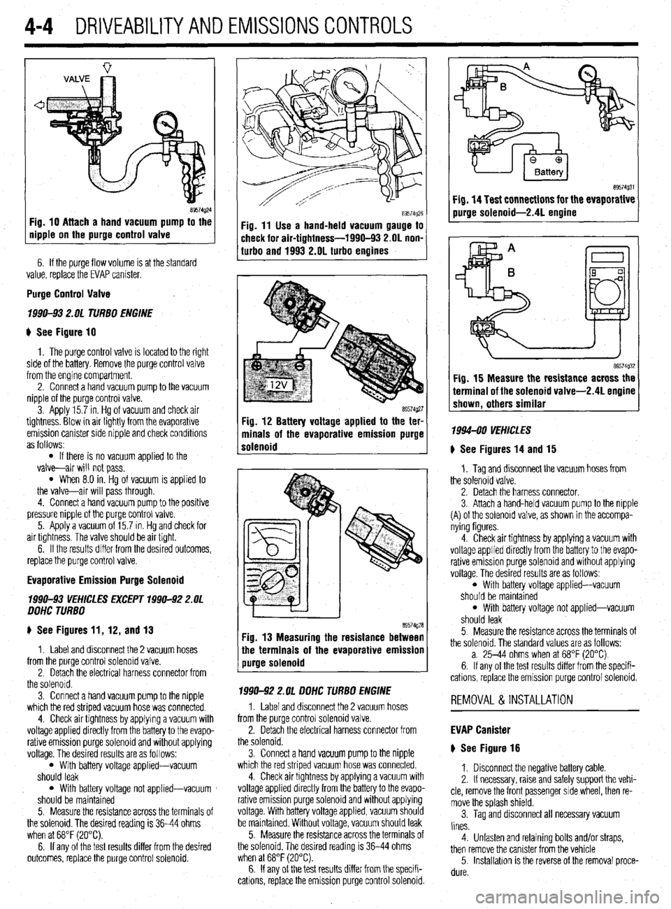
Fig. 10 Attach a hand vacuum pump to the
Ripple on the purge control valve
6. If the purge flow volume is at the standard
value, replace the EVAP canister.
Purge Control Valve
7990-93 2. OL TURBO ENGINE
u See Figure 10
1. The purge control valve is located to the right
side of the battery. Remove the purge control valve
from the engine compartment.
2. Connect a hand vacuum pump to the vacuum
nipple of the purge control valve.
3 Apply 15.7 in. Hg of vacuum and check air
tightness. Blow in air lightly from the evaporative
emission canister side nipple and check conditrons
as follows:
l If there is no vacuum applied to the
valve-air will not pass.
l When 8.0 in. Hg of vacuum is applied to
the valve-air will pass through.
4. Connect a hand vacuum pump to the positive
pressure nipple of the purge control valve.
5. Apply a vacuum of 15.7 in. HQ and check for
air tightness. The valve should be air tight.
6. If the results differ from the desired outcomes,
replace the purge control valve.
Evaporative Emission Purge Solenoid
1990-93 VEHICLES EXCEPT 1990-92 Z.OL
OOHC TURBO
p See Figures 11, 12, and 13
1. Label and disconnect the 2 vacuum hoses
from the purge control solenoid valve.
2. Detach the electrical harness connector from
the solenord.
3. Connect a hand vacuum pump to the nipple
which the red striped vacuum hose was connected.
4. Check air tightness by applying a vacuum with
voltage applied directly from the battery to the evapo-
rative emission purge solenoid and without applying
voltage. The desired results are as follows:
l With battery voltage applied-vacuum
should leak
l With battery voltage not applied-vacuum
should be maintained
5. Measure the resistance across the terminals of
the solenoid. The desired reading is 36-44 ohms
when at 68°F (20°C).
6. If any of the test results differ from the desired
outcomes, replace the purge control solenoid.
Fig. 11 Use a hand-held vacuum gauge to
check for air-tightness-1990-93 2.OL non-
turbo and 1993 2.OL turbo engines
8957dQ27 Fig. 12 Battery voltage applied to the ter-
minals of the evaporative emission purge
solenoid
89574Q28 1 Fig. 13 Measuring the resistance between
the terminals of the evaporative emission
/ purge solenoid
7990-92 2.OL OOHC TURBO ENGINE
1. Label and disconnect the 2 vacuum hoses
from the purge control solenoid valve.
2. Detach the electrical harness connector from
the solenoid.
3. Connect a hand vacuum pump to the nipple
which the red striped vacuum hose was connected.
4. Check air tightness by applying a vacuum with
voltage applied directly from the battery to the evapo-
rative emission purge solenoid and without applying
voltage. With battery voltage applied, vacuum should
be maintained. Without voltage, vacuum should leak
5. Measure the resistance across the terminals of
the solenoid. The desired reading is 36-44 ohms
when at 68°F (20°C).
6. If any of the test results differ from the specifi-
cations, replace the emission purge control solenoid.
Fig. 15 Measure the resistance across the
terminal of the solenoid valve-2.4L engine
shown, others similar
1994-00 VEHICLES
) See Figures 14 and 15
1. Tag and disconnect the vacuum hoses from
the solenoid valve.
2. Detach the harness connector.
3. Attach a hand-held vacuum pump to the nipple
(A) of the solenord valve, as shown in the accompa-
nying figures.
4. Check air tightness by applying a vacuum with
voltage applied directly from the battery to the evapo-
rative emission purge solenoid and without applying
voltage. The desired results are as follows:
l With battery voltage applied-vacuum
should be maintained
l With battery voltage not applied-vacuum
should leak
5. Measure the resistance across the terminals of
the solenoid. The standard values are as follows:
a. 25-44 ohms when at 68°F (20°C)
6. If any of the test results differ from the specifi-
cations, replace the emission purge control solenoid.
REMOVAL &INSTALLATION
EVAP Canister
p See Figure 16
1. Disconnect the negative battery cable.
2. If necessary, raise and safely support the vehi-
cle, remove the front passenger side wheel, then re-
move the splash shield.
3. Tag and disconnect all necessary vacuum
lines.
4. Unfasten and retaining bolts and/or straps,
then remove the canister from the vehicle
5. lnstallahon is the reverse of the removal proce-
dure.
Page 148 of 408
,
DRIVEABILITYAND EMISSIONS CONTROLS 4-5
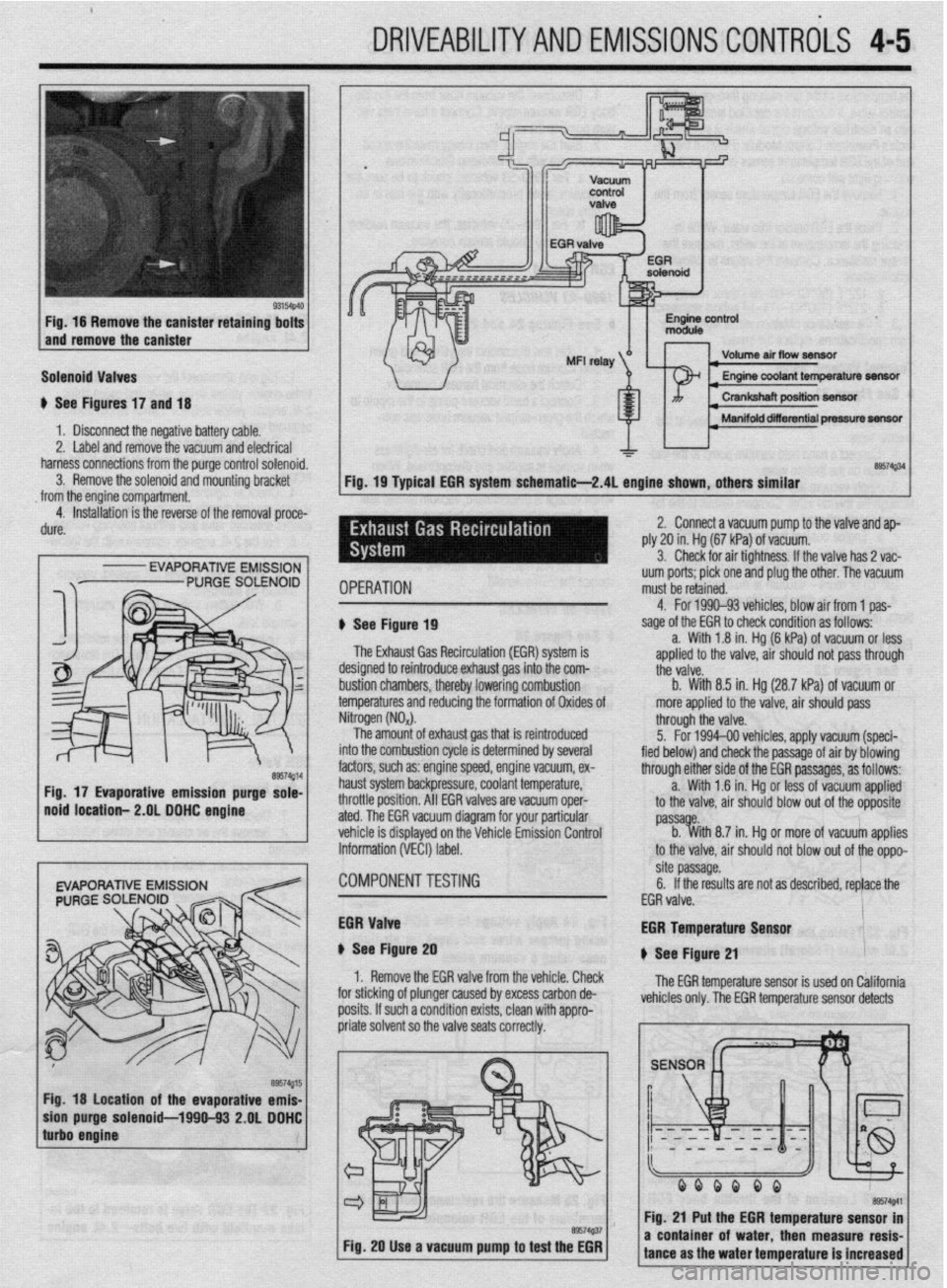
Fig. 16 Remove the canister retaining bolts
and remove the canister
Solenoid Valves
u See Figures 17 and 18
1 b Disconnect the negative battery cable.
2. Label and remove the vacuum and electrical
harness connections from the purge control solenoid.
3. Remove the solenoid and mounting bracket
from the engine compartment.
4. Installation is the reverse of the removal proce-
dure.
I
- EVAPORATIVE EMISSION
Fig. 18 location of the evaporative emis-
purge solenoid-1990-93 2.OL DDHC
Volume air flow seneftr I
I Manifold diierential pressure m
&a$34
Fig. 19 Typical EGR system schematie-2.4L engine shown, others similar
IPERATION uum ports; pick one and plug the other. The vacuum
must be retained.
1 See Figure 19
The Exhaust Gas Recirculation (EM) system is
lesigned to reintroduce exhaust gas into the com-
ttii valve.
rustion chambers, thereby lowering combustion b. With 8.5 in. Hg (28.7 kPa) of vacuum or
emperatures and reducing the formation of Oxides of more applied to the valve, air should pass 4. For 1990-93 vehicles. blow air from 1 oas-
sage of the EGR to check condition as foffows--
a. With 1.8 in. Hg (6 kPa) of vacuum or less
aoolied to the valve. air should not oass throuah
litrogen (NO,).
The amount of exhaust gas that is reintroduced
Ito the combustion cycle is determined by several
actors, such as: engine speed, engine vacuum, ex-
raust system backpressure, coolant temperature,
Irottle position. All EGR valves are vacuum oper-
ted. The EGR vacuum diagram for your particular
chicle is displayed on the Vehicle Emission Control
iformation (VECI) label. through the valve.
5. For 1994-00 vehicles, apply vacuum (speci-
fied below) and check the passage of air by blowing
through either side of the EGR passages, as follows:
a. With 1 .?I in. Hg or less of vacuum applied
to the valve, air should blow out of the opposite
passa e.
b. %ith 8.7 in. Hg or more of vacuum applies
to the valve, air should not blow out of the oppo-
:OMPONENTTESTiNG site passage.
6. If the results are not as described, replace the
EGR valve.
iGR Valve
t See Figure 20
1. Remove the EGR valve from the vehicle. Check
I”..““.
:or sticking of plunger caused by excess carbon de-
losits. If such a condition exists, clean with appro- EGR Temperature Lan*nr
u See Figure 21
The EGR temperature sensor is used on California
vehicles only. The EGR temperature sensor detects
Fig. 20 Use a vacuum pump to test the EGR
I I
a coni tance i of water. then measure resis-
I ms the water temperature is increased
Page 149 of 408
the temperature of the gas passing through +h
control valve. It converts the detected temf
Ierature
into an electrical voltage signal which is sent the ve-
hicle’s Powertrain Control Module (PCM). If the cir-
cuit of the EGR temperature sensor is broken, the
warning light will come on.
1. Remove the EGR temperature sensor from the
engine.
2. Place the EGR sensor into water. While in-
creasing the temperature of the water, measure the
sensor resistance. Compare the values to following
specifications:
a. 122°F 50°C
b. 212°F 100” )-11-14 kohms resistance
t P O-83 kohms resistance
3. If the resistance obtained varies significantly ,
.,. . .
i, replace the sensor, nom specmcaoom
Thermal Vacuum Valva
therm0 valve.
2. Connect a hand held vacuum pump to the vac-
uum hose on the therm0 valve.
3. Apply vacuum and check the air passage
through the therm0 vOrL’n %ults to the fnrm
lowinq specifications:
ant temperature of 122°F
vacuum leaks
lant temoerature of 176’F 4 n;rm.nnnn+ +h.n s,r,,~,,,,rn hnm frnm ‘h.n +hrotle
body EGR vacuum nipple. Connect a hand-held
vac-
uum pump to the nipple.
2. Start the engine, then slowly raise the speed
and compare with the following specifications.
a. For 1990-93 vehides, check to be sure the
vacuum raised proportionally with the rise in en-
gine s eed.
b. Ior 199450 vehicles, the vacuum reading
on the pump should remain constant.
EGR Solenoid
1990-93 L’EHICL ES
# See Figures 24 and 25
1. Label and disconnect the yellow and green
striped vacuum hose from the EGR solenoid.
netted.
4. Apply vacuum and check for air-tightness
when voltage is applied and discontinued. When
voltage is applied, the vacuum should be maintained.
When voltage is discontinued, vacuum should leak.
5. Measure the resistance between the terminals
of the solenoid valve. The resistance should be
36-44 ohms at 68°F (20°C).
6. If the test results differ from the soecifications.
4-6 DRIVEABILITYAND EMISSIONSCONTROLS
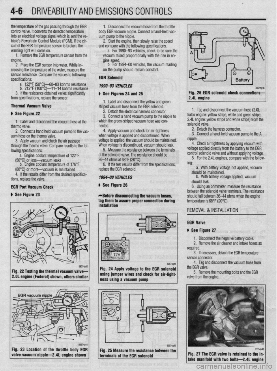
Fig. 26 EGR solenoid
check connections-
# See Figure 22
1. Label and disconnect the vacuum hose at the 2. Detach the electrical harness connector.
3. Connect a hand vacuum pump to the nipple to
which the green-striped vacuum hose was con-
(80°C) 0; more-vacuum is maintained
4. If the results differ from the desired specifica-
tions, replace the valve.
EGR Port Vacuum Check
+ See Figure 23 replace the EGR solenoid.
1994-00 VEHICLES
# See Figure 26
*Before disconnecting the vacuum hoses,
tag them to assure proper connection during
. . ** *. 1. Tag and disconnect the vacuum hose (2.OL
turbo engine: yellow stripe, white and green stripe,
2.4L engine: yellow stripe and white stripe) from the
solenoid valve.
2. Detach the harness connector.
3. Connect a hand-held vacuum pump to the A
nipple.
4. Check air tightness by applying vacuum with
voltage applied directly from the battery to the EGR
control solenoid valve and without applying voltage.
5. For the 2.4L engines, compare with the follow-
ing:
. .
roltage not applied, vacuum a. With battery
should be maintainr
b. With battery
.I III I
snoura
iea~.
sd. -
/oltage applied, vacuum
6. Using an ohmmeter, measure the resistance
between the solenoid valve terminals. The resistance
should fall between 36-44 ohms when the enaine
temperature is 68°F (20°C).
REMOVAL&INSTALLATION
EGR Valve
iI See Figure 27 mslatlanon
1 I Disconnect the negative battery cable.
2. Remove the air cleaner and intake hoses as
required.
3. If necessary, detach the EGR temperature
sensor connector.
4. Tag and disconnect the vacuum hose from
the EGR valve.
5. Remove the mounting bolts and the EGR
2.OL engine (Federal) shown, others similar
valve from the engine.
Fig. 27 The EGR valve is retained to t
take manifold with two bolts-2.4L e
Page 152 of 408
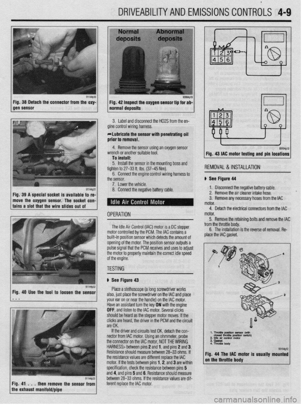
DRIVEABILITYAND EMISSIOP JSCONTRiLS 4-9
3. Label and disconnect the H02S from the en-
gine control wiring harness.
*Lubricate the sensor with penetrating oil
prior to removal.
4. Remove the sensor using an oxygen sensor
I To install: - -v- -- ---- ..----. ----...= -..- r... *-
5. Install the sensor in the mounting boss and
hl-li)r\,,.l 0 ,.l.-.f.l, .T‘fi.LI wrench or another suitable tool.
tighten to 27-33 ft. Ibs. (37-45 Nm).
6. Connect the engine control wiring harness to 1 Fia. 43 IAC mntnr tnfitinn and nin Incations 1
KtMUVHL i% IN3 I ALLA I IUN
See Fiaurr! d4
1. Disconnect the negative battery cable.
2. Remove the air cleaner intake hose.
move the oxygen sensor. The socket con- 3. Remove any necessary hoses from the IAC
OPERATION
The Idle Air Control (IAC) motor is a DC stepper
motor controlled by the PCM. The IAC contains a
built-in position sensor which detects the amount of
opening of the motor. The position sensor outputs a
pulse signal that the PCM receives and uses to adjust
the motor to properly maintain the correct idle speed
of the engine. motor.
5. Remove the retainino bolts and remove the IAC
y -_.._ -..- ._... -._ . .._ ._ from the throttle body. C The inc.hllrrti~n a 11o IIIJL(IIIoLIuII is the reverse of removal. Re-
plaie the IAC gasket.
TESTING
I
ti See Figure 43
Place a stethoscope (a long screwdriver works
also, just place the screwdriver on the IAC and place
your ear on or near the handle) on the IAC motor.
Have an assistant turn the key ON with the engine
OFF, and listen to the IAC motor. Several clicks
should be heard as the steooer motor moves. If the
clicks are heard, the driver in the PCM and the circuit
are OK.
If the driver and circuits test OK, detach the con-
nectar from IAC motor. Using an ohmmeter, probe ‘. l-!AEz?rn~ -w
2 Idle an conh0l motor nswltch)
the connector on the IAC motor, NOT THE WIRING
HARNESS> between pins 2 and 1, and pins 2 and 3.
Resistance should measure between 26-33 ohms. If
the resistance values are different replace the IAC tor is usually mounted
motor. If the tests between pins 1,2, and 3 are within
specification, check the resistance between pins 5
and 4, and pins 5 and 6. Resistance should measure
between 26-33 ohms. If the resistance values are dif-
then remove the sensor from ferent replace the IAC motor.
Page 153 of 408
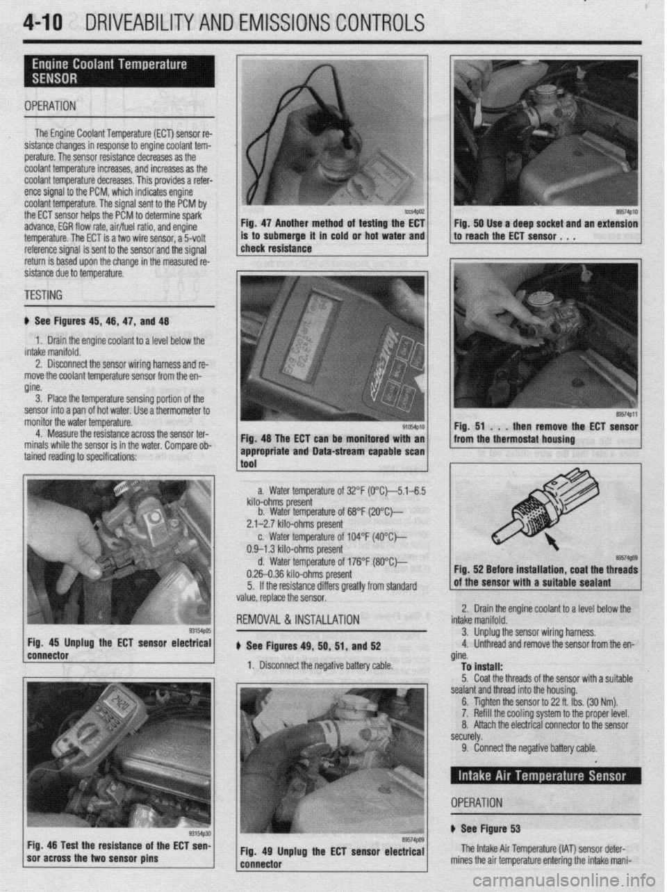
4-10 DRIVEABILITYAND EMISSIONS CONTROLS
I
OPERATION
The Engine Coolant Temperature (ECT) sensor re-
sistance changes in response to engine coolant tem-
perature. The sensor resistance decreases as the
coolant temperature increases, and increases as the
coolant temperature decreases. This provides a refer-
ence signal to the PCM, which indicates engine
coolant temperature. The signal sent to the PCM by
the ECT sensor helps the PCM to determine spark-
advance, EGR flow rate, air/fuel ratio, and engine
temperature. The ECT is a two wire sensor, a 5volt
3. Place the temperature sensing portion of the
sensor into a pan of hot water. Use a thermometer to
monitor the water temperature.
4. Measure the resistance across the sensor ter-
minals while the sensor is in the water. Comoare ob- Fig. 47 Another method of testing the EC1 Fig. 50 Use a deep socket and an extension
is to submerge it in cold or hot water and to reach the ECT sensor. 1 ,
reference signal is sent to the sensor and the signal
return is based upon the change in the measured re-
sistance due to temperature. 1 check resistance
TESTING
ti See Figures 45, 46, 47, and 48
1. Drain the engine coolant to a level below the
intake manifold.
2. Disconnect the sensor wiring harness and re-
move the coolant temperature sensor from the en-
gine.
Fig. 48 The ECT can be monitored with an
tained reading to specifications: ’
93154pos Fig. 45 Unplug the ECT sensor electrical
connector
1 soracross the two sensor pins g3154p30 Fig 48 Test the resistance of the ECT sen-
89574PlO
89574Pll
Fig. 51 . . .
then remove the ECT sensor
from the thermostat housing
a. Water temperature of 32°F (0°C~5.1-6.5
kilo-ohms present
b. Water temperature of 68°F (2O”C)--
2.1-2.7 kilo-ohms present
c. Water temperature of 104°F (4O”C)---
0.9-l .3 kilo-ohms present
d. Water temperature of 176°F (8O”Ck,
0.26-0.36 kilo-ohms present
5. If the resistance differs greatly from standard
value, replace the sensor.
REMOVAL &INSTALLATION
u See Figures 49, 50, 51, and 52
1. Disconnect the negative battery cable. Fig. 52 Before installation, coat the threads
Iolant to a level below the 2. Drain the engine c(
intake manifold.
3. Unplug1 the sensor wiring harness,
4. Unthreac
d and remove the sensor from the en-
gine.
To install:
5. Coat the threads of the sensor with a suitable
sealant and thread into the housing.
6. Tighten the sensor to 22 ft. Ibs. (30 Nm).
7. Refill the cooling system to the proper level.
8. Attach the electrical connector to the sensor
securely. appropriate and Data-stream capable scan 1
1
tnnl
9. Connect the negative battery cable.
Fig. 49 Unplug the ECT sensor electrical
---..^-s-- The Intake Air Temperature (IAT) sensor det
mines the air temnerature enterinn the! intake n er-
- ._ r_ -.-._ _. ._. J . _ ..-. ._
iani- OPERATION
+ See Figure 53
Page 154 of 408
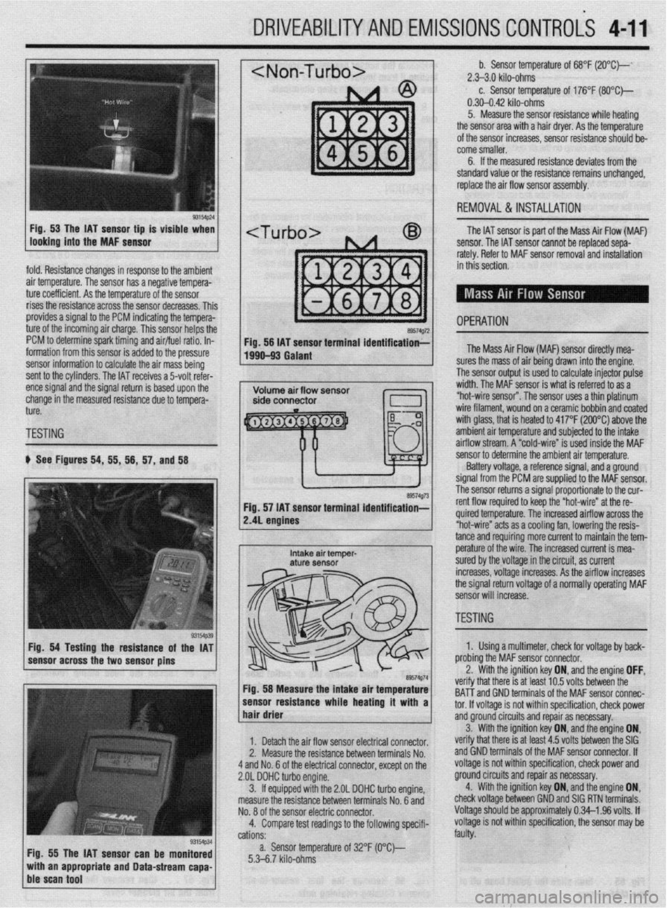
DRIVEABILITYAND EMISSIONS CONTROLi 4-11
fold. Resistance changes in response to the ambient
air temperature. The sensor has a negative tempera-
ture coefficient. As the temperature of the sensor
rises the resistance across the sensor decreases. Thil
provides a signal to the PCM indicating the tempera-
ture of the incoming air charge. This sensor helps the
PCM to determine spark timing and air/fuel ratio. In-
formation from this sensor is added to the pressure
sensor information to calculate the air mass being
sent to the cylinders. The IAT receives a 5-volt refer-
ence signal and the signal return is based upon the
change in the measured resistance due to tempera-
ture.
TESTING
b See Figures 54, 55, 56, 57, and 58
Fig. 54 Testing the resistance of the IAT
sensor across the two sensor pins
Fig. 55 The IAT sensor can be monitored
with an appropriate and Data-stream capa-
ble scan tool
~1 b. Sensor temperature of 68°F (2O”C)--‘ 2.>3.0 kilo-ohms c. Sensor temperature of 176°F (SO*C)-
0.30-0.42 kilo-ohms
5. Measure the sensor resistance while heating
the sensor area with a hair dryer. As the temperature
of the sensor increases, sensor resistance should be-
come smaller.
6. If the measured resistance deviates from the
standard value or the resistance remains unchanged,
replace the air flow sensor assembly.
1 REMOVAL&INSTALLATION
The IAT sensor is part of the Mass Air Flow (MAF)
sensor. The IAT sensor cannot be replaced sepa-
rately. Refer to MAF sensor removal and installation
in this section.
- OPERATION a9574g72 Fig. 56 IAT sensor terminal identification;-
1990-93 Galant The Mass Air Flow (MAF) sensor directly mea-
lres the mass of air being drawn into the engine.
I ?he sensor output is used to calculate injector pulse
width. The MAF sensor is what is referred to as a
“hot-wire sensor”. The sensor uses a thin platinum
wire filament, wound on a ceramic bobbin and coated
with glass, that is heated to 417°F (200°C) above the
amh+en+ nir +PmnPrfijre and subiected to the intake
..I._ ~ ..-.. .“..‘r-,u.. ai mow stream. A “cold-wire” is used inside the MAF
sensor resuirance wnoe nearmg ir wnn a 1
hair drier ‘hat melt: IS al I~“< ,“.., lvllQ UtiLnbtill ,,,=
tnd GND terminals of the MAF sensor connec-
tor. If voltaae is not within specification, check power
1. Detach the air flow sensor electrical connector.
2. Measure the resistance between terminals No.
4 and No. 6 of the electrical connector, except on the
2.OL DOHC turbo engine.
3. ff equipped with the 2.OL DOHC turbo engine,
measure the resistance between terminals No. 6 and
No. 8 of the sensor electric connector.
4. Compare test readings to the following specifi-
cations:
a. Sensor temperature of 32°F (O“C)--
5.3-6.7 kilo-ohms and groundcircuits and repair as necessary.
verify that there is at least 4.5 volts between the SIG 3. With the ignition key ON, and,the engine ON,
and GND terminals of the MAF sensor connector. If
voltage is not within specification, check power and
ground circuits and repair as necessary.
4. With the ignition key ON, and the engine ON,
check voltage between GND and SIG RTN terminals.
Voltage should be approximately 0.34-l .96 volts. If
voltage is not within specification, the sensor may be
faulty.
/ sensor to determine the ambient air temperature.
Battery voltage, a reference signal, and a ground
signal from the PCM are supplied to the MAF sensor.
rho ~pn**r rp+++rns a signal proportionate to the cur-
re. The increased airflow across the
s a cooling fan, lowering the resis-
mo more current to maintain the tem- tance and requir
e^-‘.._^ ^I LL^
I
Intake air temper- pe~a+ure UI me wire. The increased current is mea- aturf sensor sured by the voltage in the circuit, as current
increases, voltage increases. As the airflow increases
the signal return voltage of a normally operating MAF
sensor will increase.
, ~~1 TESTING - II ire” at the re-
89574g74 Fig. 58 Measure the intake air temperature
-----_ ---1-a---- L..- L--1. . . .*a 1. Using a multimeter, check for voltage by back-
nrr\hinn +hn MAF sensor connector.
the ignition key ON, and the engine OFF, .^-^ :- -’ ‘.txt In E; \mltr hahrman tha veriry t
BAT-T i
Page 155 of 408
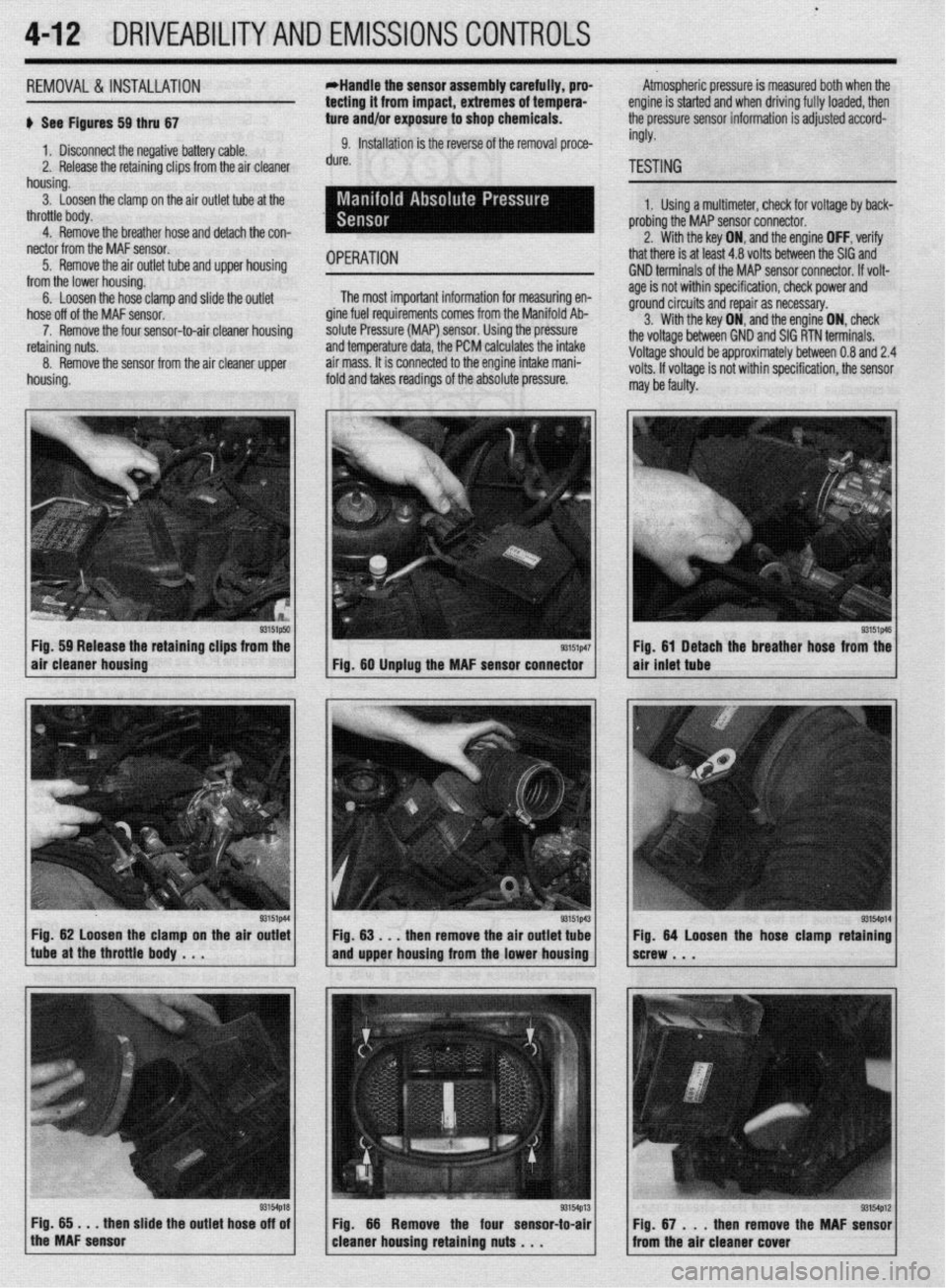
4112 DRIVEABILITYAND EMISSIONS CONTROLS
.
REMOVAL&INSTALLATION
+ See Figures 59 thru 67
1, Disconnect the negative battery cable.
2. Release the retaining clips from the air cleaner
housing.
3. Loosen the clamp on the air outlet tube at the
throttle body.
4. Remove the breather hose and detach the con-
nector from the MAF sensor.
5. Remove the air outlet tube and upper housing
from the lower housing.
6. Loosen the hose clamp and slide the outlet
hose off of the MAF sensor.
7. Remove the four sensor-to-air cleaner housing
retaining nuts.
8. Remove the sensor from the air cleaner upper
housing. Atmospheric pressure is measured both when the
engine is started and when driving fully loaded, then
the oressure sensor information is adiusted accord- *Handle the sensor assembly carefully, pro-
tecting it from impact, extremes of tempera-
ture and/or exposure to shop chemicals.
9. Installation is the reverse of the removal proce-
dure.
OPERATION
The most important information for measuring en-
gine fuel requirements comes from the Manifold Ab-
solute Pressure (MAP) sensor. Using the pressure
and temperature data, the PCM calculates the intake
air mass. It is connected to the engine intake mani-
fold and takes readings of the absolute pressure. ingly.
TESTING
1. Using a multimeter, check for voltage by back-
probing the MAP sensor connector.
2. With the key ON, and the engine OFF, verify
that there is at least 4.8 volts between the SIG and
GND terminals of the MAP sensor connector. If volt-
age is not within specification, check power and
ground circuits and repair as necessary.
3. With the key ON, and the engine ON, check
the voltage between GND and SIG RTN terminals.
Voltage should be approximately between 0.8 and 2.4
volts. If voltage is not within specification, the sensor
r nay be faulty.
Fig. 59 Release the retaining clips from the
air cleaner housing
Fig. 62 loosen the clamp on the air outlet
tube at the throttle body . . .
then slide the outlet hose off of Fig. 61 Detach the breather hose from the
air inlet tube
53154p12 Fig. 67 . . . then remove the MAF sensor
from the air cleaner cover